HART Communication on 4-20 mA: How It Works and Why It Fails
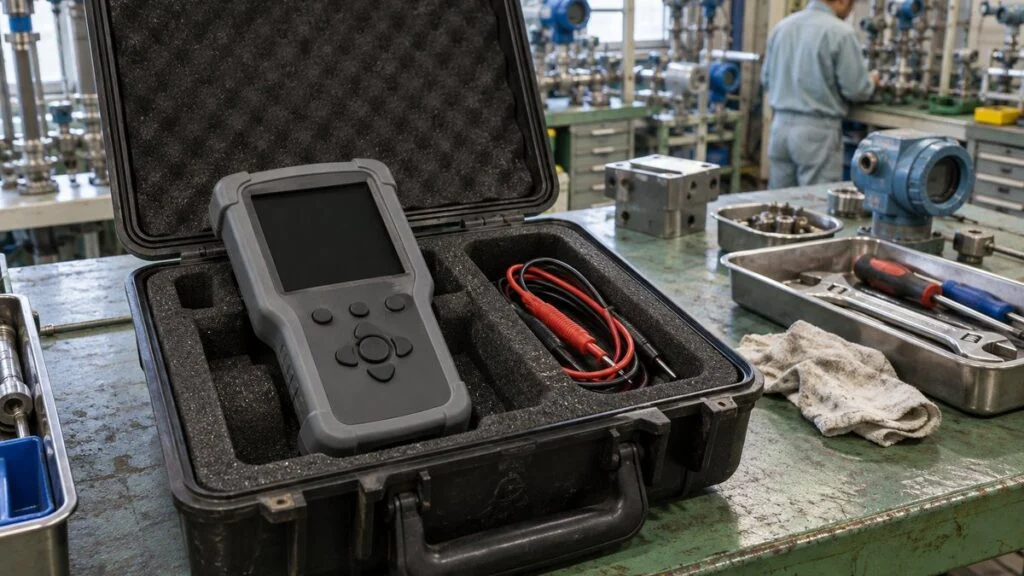
A pressure transmitter on a Japanese-built skid reads correctly on your DCS. The 4–20 mA signal is steady and the value matches the local gauge. But when you clip on a HART communicator to check the range, it reports "No device found."
The catch is that a working analog loop does not prove HART can get through. Wired HART superimposes a small digital signal on the 4–20 mA current. The DC current still carries the measured value, while the digital signal lets a host read the device's tag, range, and diagnostics, and change its settings, over the same two wires.
This guide explains how that signal rides on the loop, why HART needs a 250 Ω (or similar) load, and how to work out a voltage budget. It then walks through troubleshooting in order and ends with a checklist and questions to send to a Japanese supplier.
Contents
- What HART Adds to a 4–20 mA Loop
- How FSK Rides on the Loop: 1200 Hz, 2200 Hz, and 1200 bit/s
- What HART Gives You (and What It Doesn't)
- Limits of Wired HART
- The 250 Ω Resistor and Your Voltage Budget
- Point-to-Point vs. Multidrop
- HART Communication Not Working? Troubleshoot in This Order
- Checklist: Before You Connect the Communicator
- Questions for the Japanese Supplier
- Limits of This Guide
- FAQ
- Sources
What HART Adds to a 4–20 mA Loop
HART stands for Highway Addressable Remote Transducer. The technology originated at Rosemount and became an open standard used by many manufacturers. Today the FieldComm Group maintains the specifications and registers devices.
If you use "fieldbus" in the broad sense of any field-level communication between instruments and control systems, HART counts as one. Unlike FOUNDATION Fieldbus, which carries all information digitally, HART keeps the analog signal and adds digital communication on top. That difference changes both how the signals are handled and how the system is built.
A controller can read the measured value from a plain 4–20 mA input without any HART support. To use HART, you also need equipment that can talk to the device:
- An I/O card with HART capability, a HART modem, or a handheld communicator
- A host for maintenance work, such as asset management software
- Device definition files that match the device (covered in the troubleshooting section)
Some plants handle device configuration and status inside the DCS itself. Others use a separate maintenance system.
What you plan to do with the information decides which equipment you need.
HART also belongs to a different category from discrete I/O such as DI and DO. A contact signal is just ON or OFF, whereas HART is a communication protocol that carries named items and values between the host and the device.
Figure 1 shows a typical wired setup: a 2-wire transmitter, a 24 V supply, and a 250 Ω load. The communicator connects in parallel, not in series like an ammeter.
Figure 1: The HART Communicator Connects in Parallel at a Specified Point
An example with a 2-wire transmitter and a 250 Ω receiving load. The communicator does not go in series with the loop like an ammeter.
Polarity marks follow the current direction shown. Protective devices, shielding, and grounding are omitted. The actual connection points and required load are set by the device manual and the loop diagram.
The communicator sends requests to the device and reads the replies from the signal on the loop. Instead of a dedicated handheld, you can also use a PC with a HART modem or a HART-capable I/O module.
The basic pattern is request and response. The host (the "master") sends a command, and the field device answers with its measured value, settings, or status. HART allows two masters on a loop: a primary master, usually the control system, and a secondary master, such as a handheld or laptop in the field.
How FSK Rides on the Loop: 1200 Hz, 2200 Hz, and 1200 bit/s
Wired HART uses frequency shift keying (FSK) based on the Bell 202 standard. A 1200 Hz tone represents a binary 1 and a 2200 Hz tone represents a 0. The signal is small, about ±0.5 mA around the loop current.
Do not confuse the frequencies with the data rate. Hz counts wave cycles per second, while bit/s counts bits per second. Wired HART runs at 1200 bit/s; there is no "1200–2200 bit/s" speed range, even though the numbers look similar.
Figure 2 separates the two ideas: the DC average that carries the measured value, and the tone frequencies that carry the data.
Figure 2: The Average Current vs. the Frequency of the Data Signal
Top: a small AC signal on an example DC level of 12 mA (not to scale). Bottom: how many cycles each tone completes in the same 2.5 ms window, which is not a bit period.
1200 Hz × 0.0025 s = 3 cycles; 2200 Hz × 0.0025 s = 5.5 cycles. Neither number is the data rate of 1200 bit/s.
Because the tones average out to zero, they do not shift the DC value, and the analog signal keeps working. On the receiving side, separate circuits pick up the DC level for the measurement and the AC tones for communication.
Check the HART reading and the current-to-value scaling separately. If the analog input range in the DCS differs from the transmitter's range, the displayed value will be wrong even when the current is correct.
What HART Gives You (and What It Doesn't)
The main benefit is access to device information that the current alone cannot carry, without new wiring. From a maintenance tool you can check the range, units, tag, and device status in one place.
What you can read depends on the device. A dual-element temperature sensor, for example, has two sensing elements but not necessarily two current outputs.
The variables and diagnostics available over HART depend on the transmitter's input configuration and the functions it supports.
Figure 3 compares what a plain 4–20 mA input gives you with what HART can add.
Figure 3: The Current Carries the Value; HART Carries Device Information
To use what a HART device can provide, the host side must be able to handle it too.
| Item | Plain 4–20 mA input | Examples of what HART adds |
|---|---|---|
| Measured value | Current scaled to the configured range | Digital value, units, and status |
| Device identity | Matched against drawings, terminal numbers, and field labels | Tag, device type, serial number, and similar |
| Range | Receiver and field settings checked one by one | Lower and upper range values read from the device |
| Maintenance clues | Abnormal current and field inspection | Device status, extra variables, and diagnostics |
| What the receiver needs | An analog input | A compatible host, a communication path, and device definition files |
Not every device provides all of this, or in the same form. What you get depends on the model, revision, and what the host supports.
During commissioning, match each field tag to its design measurement point and confirm the units and range. Reading the settings with a HART tool and exporting them to a list saves collecting them by hand.
Example: The Current Is Right but the Display Is Wrong
Take a transmitter set to 0–1 MPa (0–145 psi) with a 4–20 mA output. At 0.5 MPa it outputs 12 mA. If only the receiver is set to 0–2 MPa, the display shows 1 MPa.
The current itself is exactly what the transmitter's range says it should be. Read the device's range and digital value over HART and compare them with the receiver's scaling. That comparison isolates the cause of the mismatch.
When you compare a local gauge with the transmitter and the screen, match the units and the pressure reference (gauge or absolute), not just the numbers. A compound gauge scale can also help confirm the range.
During operation, changes in device status help you decide which instruments to inspect first. Diagnostics are most useful when you weigh them against the process conditions and other measurements.
Because HART is an open standard, it is designed to work across devices from different manufacturers. That also makes it easier to standardize how you check devices, hosts, and definition files when equipment is installed at sites outside Japan.
Keep in mind that re-ranging a transmitter over HART is not calibration. Changing the range does not verify sensor accuracy; that still requires a reference standard and a check of the measurement chain.
Limits of Wired HART
At 1200 bit/s, wired FSK is not suited to sending images or large amounts of waveform data. Reading many items from several devices one after another also adds up to noticeable waiting time.
Speed is not the only factor. Each request and response carries more than the measured value, and the command type, the host's scan, and the device's response time all affect the overall update cycle. As a result, designers usually keep the 4–20 mA path for control and treat HART data as a separate, slower update for maintenance.
If you plan to use HART digital values in control, compare the update rate you need with what the system actually delivers, and choose how the host will bring the data in.
The signal path matters too. HART can fail on a loop where the analog value arrives perfectly, depending on how devices in between handle the AC signal:
- Signal converters and isolators
- Intrinsic safety barriers
- Filters
For an isolator, look beyond its 4–20 mA accuracy and check whether it relays HART in both directions. A device that reproduces the DC value correctly does not necessarily pass the AC signal.
Finally, the host needs the right support for each device. Reading the basic measured value needs less than detailed diagnostics and configuration, so match the software and device definition files to the items you want to use.
The 250 Ω Resistor and Your Voltage Budget
HART needs a certain amount of resistance in the loop so that the current-mode signal from the device produces a voltage the host can detect. The HART specification calls for a total loop load, including cable resistance, of at least 230 Ω and at most 1100 Ω. Many device manuals specify 250 Ω, which sits just above that minimum.
The device manual states the load the device needs for communication. The resistor may already be built into the receiving input or the power supply, so a separate one is not always required.
If you add a resistor without checking for an existing one, you add an extra voltage drop. First find where the existing load is, then check it against the device's communication requirements and the supply's capability.
Figure 4 works through a voltage budget with assumed values.
Figure 4: Voltage Across 250 Ω and the Voltage Left for the Transmitter
The values are assumptions for illustration: a 24 V supply, a 250 Ω receiving resistor, 50 Ω of round-trip wire resistance, and a 2 V drop across an intermediate device.
For real equipment, use the supply's minimum voltage, the maximum operating and alarm currents, and the specifications of every device in the loop. The load requirement and the voltage requirement must both be met.
Passing 4–20 mA through 250 Ω gives 1–5 V, so the same resistor also serves an analog voltage input. On Japanese drawings this resistor may be labeled 受信抵抗 (jushin teiko, receiving resistor).
In the example, 16 V remains at the transmitter at 20 mA, leaving a 4 V margin over the assumed 12 V minimum. With the same equipment, that margin shrinks if the supply voltage drops or the cable gets longer.
If the device uses alarm currents, calculate the drop at that current. With the same assumptions at 22 mA, the resistor drops 5.5 V and the wire 1.1 V, leaving 15.4 V at the transmitter.
The 22 mA figure is only for this example; alarm currents vary by device. Calculating at the device's maximum current reveals voltage shortfalls that never show up within the normal measuring range.
The resistor value alone does not decide communication quality. It affects both the voltage the analog input sees and the impedance of the communication path, so the cable and connected devices must suit the loop as a whole.
How Japanese Specs Express Load and Supply
Japanese datasheets often state the allowable load as a formula rather than a single number. It is labeled 許容負荷抵抗 (kyoyo fuka teiko, allowable load resistance).
For example, one HART-compatible isolator from MG Co., Ltd. gives the allowable load as (supply voltage − 12 V) ÷ 0.02 A, including lead resistance. The same datasheet requires a loop resistance of 250 Ω ±10% for HART communication.
Japanese DCS input cards may also have the load built in. One Yokogawa I/O module datasheet lists a 2-wire input resistance of 400 Ω (at 20 mA) to 750 Ω (at 4 mA) and HART support. Read the card's specification before adding a resistor.
Point-to-Point vs. Multidrop
In a typical point-to-point loop, one transmitter sits on one current loop and sends its main measured value as 4–20 mA. HART lets you read that device's digital values and settings over the same wires.
In multidrop, several devices share one pair of wires and the host identifies each by its address. When the devices are set to a fixed current, the host reads each measured value digitally. The total current tells you nothing about the individual values.
Figure 5 compares the two configurations.
Figure 5: Adding Up the Currents Does Not Give the Individual Values
In the lower example, devices A, B, and C are each fixed at 4 mA, so the loop carries 12 mA in total. The number of devices and the address range depend on the HART revision and the device specifications.
The power supply, communication interface, and load are drawn together on the host side. Top: one loop. Bottom: devices connected in parallel on the same pair of wires.
For older devices (HART revisions 3 to 5), polling addresses run from 1 to 15, which is why many references give a limit of 15 devices. HART 6 and 7 allow addresses up to 63, but the real maximum depends on each device. Polling addresses above 15 on a loop that mixes older and newer devices can cause communication errors.
An existing analog input and a multidrop network need different wiring and settings. Check the current output mode as well as the address, and decide which path each value will be read from.
A fixed-current multidrop network still needs its power supply checked. All device currents flow through the shared load, so evaluate the supply voltage and current capacity for the full set of connected devices.
HART also has versions that use other media, such as WirelessHART and HART-IP. The Bell 202 frequencies and 1200 bit/s rate apply only to wired HART, not to the wireless or Ethernet physical layers.
HART Communication Not Working? Troubleshoot in This Order
Work from power and wiring toward software. Each step rules out a layer before you move to the next. Before opening a junction box or touching terminals, follow your site's permit, isolation, and hazardous-area procedures; this guide does not replace them.
- Power and analog current. Confirm the device has enough voltage and the 4–20 mA output is what you expect. Trace the supply, receiving load, intermediate devices, and wiring on the loop diagram, then work out the voltage budget as in Figure 4.
- Connection point and load. Check where the communicator is connected and how much load the loop presents against the device manual. Connect in parallel at the specified point; inserting the tool in series like an ammeter changes the loop circuit.
- Protocol. Confirm the device actually uses HART. On some Japanese equipment it may use a different protocol (see the next section).
- Devices in the path. Check whether isolators, barriers, and converters are marked HART-compatible and which direction they pass the signal. If you can read the device on one side of an isolator but not the other, look at its relay function and which side you are connected to.
- Wiring and noise. Look for loose connections and miswiring, and check for electrical interference nearby. Follow the site's and device's wiring specifications for shielding and grounding.
- Host support. If communication works but some settings do not appear, check the device definition files. DD, DTM, and FDI packages are tied to device type and revision, so load the matching files on the host.
- Value comparison. Compare the primary variable read over HART with the signal actually used for control. Keeping control values separate from monitoring and maintenance values makes it easier to tell a communication problem from a display or control problem.
On a running plant, a configuration change can affect operation. Manage reading and writing separately, record the values before any change, and follow the site's management-of-change procedure.
Japanese Equipment: Check for BRAIN Before Blaming the Loop
Yokogawa, a major Japanese instrument maker, also uses its own digital protocol called BRAIN. Some of its transmitters are sold in both BRAIN and HART versions with the same sensing element, and the protocol is set by the model code. Do not assume the two protocols are interchangeable.
A BRAIN device is generally not reachable with a standard HART communicator; Yokogawa lists its BT200 handheld as the communicator for BRAIN devices, and its FieldMate software is another option. Confirm with the manufacturer which tool your model needs. Before you change resistors or rewire, read the full model code on the nameplate and check it against the manufacturer's model code table.
Japanese manuals may also cover the HART and BRAIN versions in separate documents. Make sure the manual you are reading matches the protocol on the nameplate.
Japanese Terms You May See
These terms appear in Japanese loop diagrams, datasheets, and manuals for HART loops.
| Japanese | Romaji | Meaning |
|---|---|---|
| HART通信対応 | HART tsushin taio | HART-compatible (check for the same wording on isolators and barriers) |
| 受信抵抗 | jushin teiko | Receiving resistor, typically 250 Ω (gives 1–5 V) |
| 負荷抵抗 | fuka teiko | Load resistance |
| 許容負荷抵抗 | kyoyo fuka teiko | Allowable load resistance, often given as a formula |
| ループ図 | rupu-zu | Loop diagram |
| 取扱説明書 | toriatsukai setsumeisho | Instruction manual |
| 双方向 | sohoko | Bidirectional (whether an isolator relays HART both ways) |
Checklist: Before You Connect the Communicator
Run through these items before you spend time in the field.
- Device protocol confirmed as HART (not BRAIN or another protocol) from the full model code
- HART revision of the device, and whether the host and communicator support it
- Location and value of the existing load resistor, including any built into the input card or power supply
- Total loop load within the device's communication requirement (the HART specification's range is 230–1100 Ω)
- Voltage at the transmitter at its maximum current, including alarm current, above its minimum operating voltage
- Every isolator, barrier, and converter in the loop marked HART-compatible, and passing HART in the direction you need
- Communicator connection point specified in the manual, and connected in parallel
- Only one secondary master (handheld or laptop) on the loop at a time
- Polling address and current output mode (normal 4–20 mA or fixed current)
- Matching DD, DTM, or FDI package for the device type and revision on the host
- Receiver scaling matched to the transmitter range and units
- Existing values recorded and the site's change procedure followed before writing any setting on a live loop
Questions for the Japanese Supplier
If documents are missing or unclear, ask the supplier directly. These questions cover the points above.
- Which protocol does each transmitter use (HART, BRAIN, or other)? Please give the full model code.
- Which HART revision does each device support?
- Where is the HART load resistor in each loop, and what is its value? Is it built into the input card or power supply?
- What is the minimum operating voltage of each transmitter, and what alarm current is it set to?
- Are the isolators and barriers in the panel HART-compatible, and do they relay HART in both directions?
- Where should a handheld communicator be connected? Please mark the points on the loop diagram.
- Which DD, DTM, or FDI files are needed, and where can we download them?
- Are any devices wired in multidrop or set to fixed current?
- Can you provide the English versions of the manuals and loop diagrams for these devices?
A short inquiry along these lines usually gets a clearer answer than a general "HART does not work":
Subject: HART communication check – [project name], tag [PT-101]
We cannot communicate with transmitter [PT-101] using a HART communicator, although the 4–20 mA signal reads correctly in the DCS. Could you please confirm the following for this loop: (1) the full model code and communication protocol of the transmitter, (2) the location and value of the HART load resistor, (3) whether the isolator [model] relays HART in both directions, and (4) the recommended connection point for a handheld communicator? A marked-up loop diagram would be very helpful.
Limits of This Guide
- This guide covers wired HART on 4–20 mA loops. WirelessHART and HART-IP use different physical layers.
- The voltage budget in Figure 4 uses assumed values. Use the actual specifications of the supply, cable, and every device in the loop.
- Load requirements, alarm currents, address ranges, and supported features vary by device, revision, and host. The device manual takes precedence over general figures here.
- Intrinsically safe loops have their own rules for barriers and connected equipment. Whether a communicator may be connected in a hazardous area is decided by the site's approvals and procedures, not by this guide.
- Changing settings on a running plant follows the site's own procedures.
FAQ
Does HART Need Special Cable?
No. HART is designed to run on existing two-wire instrument loops. The wiring, load, and intermediate devices must still meet the communication requirements, so check the whole current loop rather than just the cable type.
If the 4–20 mA Signal Is Fine, Will HART Work?
Not necessarily. The DC value can arrive correctly while an isolator or other device blocks the AC communication signal. Check that the device and host support HART, that the load and voltage are within requirements, and that every device in between relays HART in both directions.
Do I Always Need to Add a 250 Ω Resistor?
No. Some receiving inputs and power supplies already include the required load. Find the existing load on the loop diagram, then decide whether more is needed to meet the device's communication requirement without losing your voltage margin.
Why Does the HART Value Differ from the DCS Display?
The HART digital value and the scaled 4–20 mA display take different paths. Compare the variable, units, range, and receiver scaling, and check each step to see where the value changes.
Are 1200 Hz and 1200 bit/s the Same Thing?
No. Hz is the frequency of the wave, and bit/s is the rate at which information is sent. Wired HART uses 1200 Hz and 2200 Hz to represent 1 and 0, and its data rate is 1200 bit/s.
Sources
- HART basics and IIoT: Endress+Hauser, "The essentials of HART communication and the IIoT"
- FSK frequencies, data rate, ±0.5 mA signal, 230–1100 Ω loop load, two masters, multidrop addresses 1–15: SAMSON, "HART Communications" (Technical Information L452 EN)
- HART revisions and polling address ranges: Wikipedia, "Highway Addressable Remote Transducer Protocol"; Endress+Hauser, BA00486C operating instructions
- HART overview: Yokogawa, "What is HART communication?" (Japanese)
- HART-capable I/O module input resistance: Yokogawa, GS 33K50F80-50E, I/O Modules with Built-in Barrier (for FIO)
- HART principles: Emerson, FIELDVUE DVC6200 instruction manual
- Connecting a HART configuration tool: Yokogawa, digitalYEWFLO instruction manual (Japanese)
- HART-compatible isolator (bidirectional relay, 250 Ω ±10%, allowable load formula): MG Co., Ltd., M2DYHR product specifications (Japanese)
- BRAIN and HART communicators: Yokogawa, Device Smart Communicators; Yokogawa, DPharp EJA Series HART protocol manual (IM 01C22T01-01EN)
- Device definition files: FieldComm Group, "HART EDD/FDI Registration"; Yokogawa, FieldMate and DD/DTM FAQ (Japanese)
- Origin of HART and open standard: Emerson, Rosemount pressure innovation history
- Multiple sensor inputs and primary variable: Emerson, Rosemount 3144P reference manual
Original article in JapaneseThis guide is adapted from a MONOSCOPE article written for readers in Japan: HART通信とは?4-20mAへの重畳・仕組みとメリット、通信できない原因
About the editor
 MONOSCOPE EditorFOUNDER & EDITOR
Spent about ten years at a plant equipment maker and a plant engineering company, proposing, designing, and commissioning equipment, then moved into web marketing. Now a web consultant for B2B manufacturers, helping them explain their products and technology. Licensed in Japan as an Energy Manager and a Third-Class Chief Electrical Engineer.
Has run an engineering blog since 2017 (500+ articles) and a Japanese YouTube channel with about 20,000 subscribers. Each English guide is written from the Japanese shop-floor point of view and checked against the cited standards.