Cobot Deployment: 6 Steps from Risk Assessment to Start-Up
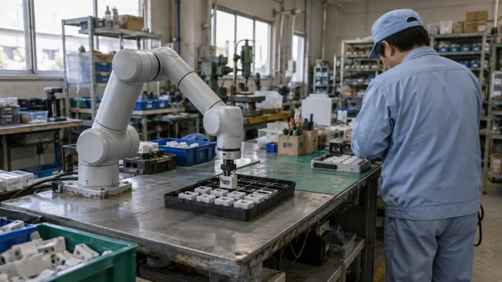
Your plant has just bought a collaborative robot from a Japanese maker such as FANUC, DENSO, or Kawasaki. The plan is to run it next to operators with no fence. The supplier's documents mention "80 W," a 2013 notice from Japan's labor ministry, and JIS B 8433, and you are not sure which of these applies to you.
The short answer: no cobot is "safe" on its own. Whether you can run it without a fence depends on the whole application: the robot, the end effector (gripper or tool), the parts it handles, the equipment around it, and how people move near it. You assess the risk of that application and meet the standards and regulations that apply where the robot is installed.
This guide walks through cobot deployment in six steps, from picking the process to start-up. It covers risk assessment and the role of ISO/TS 15066, the 2025 revision of ISO 10218, and an overview of how Japan's rules relate. It ends with common failures, questions to ask the Japanese side, and an email template you can reuse.
Contents
- What a Cobot Is, and Why the Robot Alone Is Not "Safe"
- Collaborative Robot Implementation Steps at a Glance
- Steps 1–2: Pick the Process and the Collaboration Mode
- Step 3: Cobot Risk Assessment and the Role of ISO/TS 15066
- Step 4: Standards and Regulations (Overview Only)
- Steps 5–6: From Integrator Selection to Start-Up
- Common Cobot Deployment Failures and How to Avoid Them
- Questions to Ask the Japanese Supplier or Integrator
- Limits of This Guide
- FAQ
- Sources
What a Cobot Is, and Why the Robot Alone Is Not "Safe"
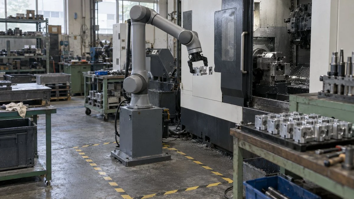
A collaborative robot (cobot) is designed to work in the same space as people instead of behind a safety fence. Many models detect contact force and stop, or slow down when a person approaches. Typical jobs are assembly, packing, and loading and unloading machines.
According to the International Federation of Robotics (IFR), cobots made up 10.5% of the industrial robots installed worldwide in 2023. They are still a minority, but more plants now consider them for labor shortages and for processes that do not justify a dedicated automated line.
The point people most often miss is that cobot safety does not end with the robot. JIS B 8433-1, the Japanese version of ISO 10218-1, treats the robot as only one component of the final collaborative robot system. The standard states that the robot alone is not enough for safe collaborative operation.
Here is a simple example. A low-force robot fitted with a gripper that picks up sharp parts still creates a cut hazard. The 2025 edition of ISO 10218 makes this even clearer: it frames safety around assessing each collaborative application rather than a "collaborative robot."
So treat the process, not the robot, as the unit you deploy. The rest of the steps make more sense from that angle. Figure 1 compares a fenced cell with a fenceless collaborative setup.
Without a fence, your own risk assessment and documents have to show why the application is safe.
In Japan, robots whose drive motors are rated 80 W or less fall outside the industrial robot rules, but hazards from the end effector and parts still need to be assessed.
Collaborative Robot Implementation Steps at a Glance
Cobot deployment runs in three phases (planning, safety design, and implementation) and six steps. The key difference from an ordinary equipment project is that safety design runs in parallel with robot selection, not after the purchase order.
Finish the safety work before you order, then confirm it on the real equipment at start-up.
Steps 3 and 4 go back and forth. Every design change means repeating the assessment.
Steps 1 and 2 decide where the robot works, why, and how it interacts with people. Steps 3 and 4 show that this way of working is safe. Steps 5 and 6 turn the result into equipment and make it stick on the shop floor.
Steps 1–2: Pick the Process and the Collaboration Mode
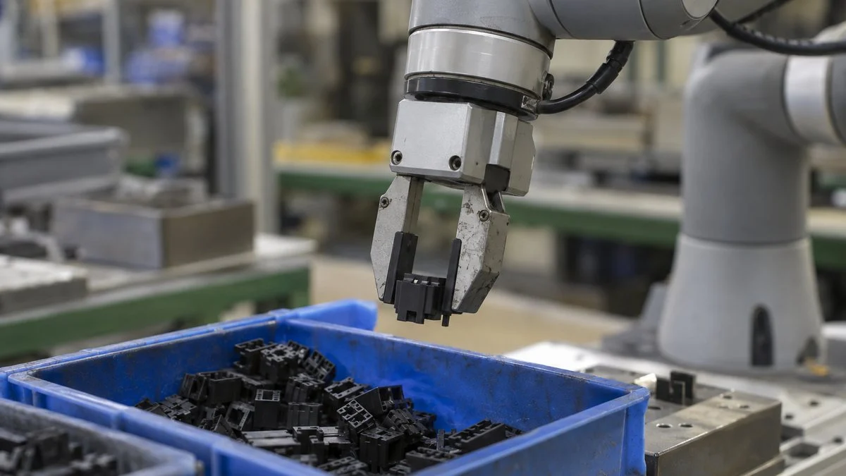
The first step is choosing which process the cobot will take over. Get this wrong, and the cell often fails to pay for itself, no matter how many safety measures you add later.
Processes That Suit Cobots, and Processes That Do Not
Cobots usually run with limited speed and force so that contact does not cause serious injury. As a result, a conventional fenced robot is often the better choice for high-speed, high-volume repetition.
Cobots do well when you want to automate only part of a process, change over often, or have little floor space. Rather than replacing an operator's whole job, a practical split is to hand off simple tasks such as part feeding or screw driving. The operator keeps the judgment calls and fine adjustments.
Figure 3 sums up which processes suit cobots and which need a closer look.
Judge by whether the work can be shared with people and whether the layout needs flexibility, not by speed.
These are rules of thumb. The final decision comes from the risk assessment in Step 3.
Before you choose, measure the current cycle time, the weight, shape, and variation of the parts, and the operators' walking paths. Integrators will always ask for these numbers when you request a quote, and the more complete your data, the faster the review goes.
Choose One of the Four Collaborative Modes
Once the process is set, decide how people and the robot will interact. ISO 10218-1:2011 (JIS B 8433-1:2015 in Japan) lists four modes of collaborative operation. The mode you choose determines the sensors, safety functions, and robot you need.
One mode stops the robot, one lets the operator guide it by hand, one controls distance, and one allows contact within limits.
Names follow ISO 10218-1:2011, shortened. Some 2025-edition summaries call "safety-rated monitored stop" "monitored standstill"; check the wording in the edition you use. One process can combine several modes.
When a cobot works beside a person without a fence, the design usually centers on power and force limiting. Relying on force limits alone, however, makes the assessment harder where the robot path passes at head or neck height, or where a person could be trapped against nearby equipment.
In some cases, combining force limiting with a no-contact mode lets the robot run faster, for example when nobody is nearby.
Step 3: Cobot Risk Assessment and the Role of ISO/TS 15066

Risk assessment decides whether collaborative operation works. For a cobot, it follows the usual pattern: identify hazards, estimate the size of each risk, and reduce the risks in order of priority.
For power and force limiting, the assessment also needs contact limits. ISO/TS 15066:2016 set out biomechanical limits for the force and pressure allowed when a robot touches a person.
In the 2025 revision, that content was consolidated into ISO 10218-2, so check which document and edition an assessment cites.
In Japan, a companion notice issued with the 2013 notice (Kian-anpatsu 1224 No. 1) asks users to follow the national guideline on comprehensive safety standards for machinery. That guideline sets out how to identify machine hazards and the priority order for risk reduction.
The sections below use it as a worked example; your local regulations and standards set what actually applies to you.
How Wide to Look for Hazards
Do not stop at normal operation. The Japanese guideline lists these situations to cover when identifying hazards:
- Work in the intended use, including setup, teaching, operation, cleaning, and maintenance
- Work at the start of use, such as transport, installation, and trial runs
- Work at the end of use, such as dismantling and disposal
- Work during breakdowns or abnormal conditions
- Reasonably foreseeable misuse, such as taking shortcuts
- People other than the robot's operators coming close
For a cobot, that includes other workers walking along an aisle and forklift drivers bringing in parts. Think beyond people who follow the work instruction, and include what people are likely to do when they are in a hurry.
A failure mode and effects analysis (FMEA) of the process helps you catch work during abnormal conditions.
Three Things to Look at When Estimating Risk
Japan's 2013 notice names three points that need special attention when estimating cobot risk:
- The force and kinetic energy of the robot arm and other moving parts
- The chance of a person being trapped between the arm and surrounding structures
- The arm shape and working conditions, such as protrusions that could hit the eyes, sharp edges, and pinch points between joints
On trapping, the notice gives examples of conditions that can be judged free of this hazard. One is keeping at least 500 mm (about 20 in) between the arm and surrounding structures at their closest point. Another is when a trapped person can be released by hand, without drive power.
These are examples from a Japanese notice, not universal limits, so confirm the criteria in the standard you work to. In practice, placing a robot near the edge of a workbench or a column makes the trapping assessment harder, so think about it at the layout stage.
Risk is normally estimated for the most likely injury. The guideline also asks you to consider the most serious foreseeable injury, even if it is unlikely. Instead of assuming "it stops if it hits someone," think about what can happen before it stops.
Choose Risk Reduction Measures in Priority Order
If an estimated risk is not acceptable, plan measures to reduce it. Do not pick whatever is easiest; work down the priority order in Figure 5.
Each lower level only covers the risk the level above could not remove.
Based on the employer's actions in Japan's guideline on comprehensive safety standards for machinery. Also check that a measure does not create a new hazard.
With cobots, a surprising amount can be done at level 1. Routing the robot away from head height, or changing how the part is gripped so protrusions do not point at the operator, costs almost nothing. Before adding sensors, see whether layout and motion can reduce the risk.
Record the Results and Review After Every Change
Record the assessment results, the measures taken, and the residual risks. Keep them with the instruction manual and other information for use from the robot maker. In Japan, the 2013 notice also requires the results to be recorded and kept under the national risk assessment guideline.
This record is your basis for running without a fence. Set a rule from day one: whenever an assumption behind the assessment changes, review it. That includes a new end effector, a new part, or moving the robot.
Step 4: Standards and Regulations (Overview Only)
Alongside the risk assessment, confirm the legal and standards basis for running without a fence. This section is an overview to help you read the documents. Which rules apply, and how to comply, depends on where the cobot is installed, so confirm with a qualified safety professional and the robot maker.
ISO 10218 Was Revised in 2025
ISO published revised editions of ISO 10218-1 (the robot) and ISO 10218-2 (robot applications and robot cells) in February 2025. This was a major revision of the 2011 editions. Most of ISO/TS 15066, the technical specification with detailed requirements for collaborative applications, was folded into ISO 10218-2.
The main changes include:
- Safety framed around the collaborative application rather than the "collaborative robot"
- Two robot classes: Class 1 for very weak robots that pose no significant hazard, and Class 2 for all other industrial robots
- Required performance levels set per safety function, instead of one blanket level for the whole robot
- New requirements on topics including cybersecurity and manual load stations
In the US, ANSI/A3 R15.06-2025, published in September 2025, is the national adoption of ISO 10218 Parts 1 and 2. It replaces the 2012 edition.
In Japan, the national versions JIS B 8433-1 and -2 were still the 2015 editions based on ISO 10218:2011 when the Japanese edition of this article was written. TS B 0033:2017, Japan's version of ISO/TS 15066, was withdrawn in March 2025 when it expired.
Before you rely on any of these, check the current status with the Japanese Standards Association or your supplier.
Because of this mix of editions, write down which edition each assessment and document is based on. A Japanese supplier's file may cite ISO 10218:2011 or JIS B 8433:2015, while your local rules may already reference the 2025 edition.
How Japan's 80 W Rule and Safety Ordinance Relate
You will see these Japanese rules in documents from Japanese makers and parent companies. They apply to robots installed in Japan; they do not replace the regulations in your country.
- Ordinance on Industrial Safety and Health: Japan's safety rules for industrial robots. Machines whose drive motors are rated 80 W or less fall outside the industrial robot rules. This is the so-called "80 W rule."
- Article 150-4: For robots above 80 W, the employer must take measures such as installing a fence or enclosure when contact with a running robot could endanger workers. A model sold as a cobot is covered if its rated output is above 80 W.
- 2013 notice (Kihatsu 1224 No. 2, December 24, 2013): The Ministry of Health, Labour and Welfare (MHLW) clarified when robots above 80 W can work alongside people without a fence. Meeting either of the two routes in Figure 6 is enough.
Figure 6 compares the two routes in the 2013 notice.
Either route requires documents that explain why the setup is safe.
Based on the MHLW leaflet (December 2013). The notice was written for ISO 10218:2011.
In practice, the robot maker usually shows that the robot meets ISO 10218-1, the integrator designs and assesses the system, and the user confirms the final way of working. Whatever the route, the user should be able to answer "On what basis are we running this without a fence?"
If your cell is in Japan, the ordinance also requires special education (tokubetsu kyoiku, a mandatory safety course) for workers who teach robots above 80 W inside their operating range, or inspect them inside that range while they run (Article 36, items 31 and 32). Teaching includes setting motion order or positions by moving the arm by hand.
Other provisions cover written teaching procedures, immediate stopping and "work in progress" signs on start switches (Article 150-3), emergency stop checks before work (Article 151), and stopping and locking start switches during inspection and repair (Article 150-5).
Ask for the Technical File and Declaration of Conformity
For the ISO route, the technical file and the declaration of conformity carry the most weight. The MHLW leaflet lists these contents for the technical file:
- Overall machine drawing and control circuit diagrams
- Detailed drawings, calculations, and test results
- Documents showing the risk assessment procedure and residual risks
- Standards applied
- A copy of the instruction manual
A declaration of conformity is a document in which the manufacturer or another responsible party declares that the machine meets all relevant provisions of the safety standards. If you do not confirm at the quote stage who prepares and delivers which documents, you may find just before start-up that only the robot's own documents exist.
Steps 5–6: From Integrator Selection to Start-Up
Once the safety requirements are set, turn them into equipment. Cobots are easy to teach, and some companies commission them in-house. Once end effector design and safety assessment are included, though, most companies hire a system integrator.
Choosing an Integrator and Writing the Specification
Look beyond robot programming experience. Check whether the integrator has carried out risk assessments and contact force measurements for collaborative applications themselves.
Besides cycle time and target parts, write these items into the specification:
- The collaborative mode or modes to be used
- Allowed contact conditions
- The standard and edition used for assessment
- The documents to be delivered
Japan's machinery safety guideline also asks employers to choose machines designed with safety in mind and to include safety conditions in the order where needed. Starting the safety discussion after you order leads to costly rework.
What to Verify on the Real Cell After Installation
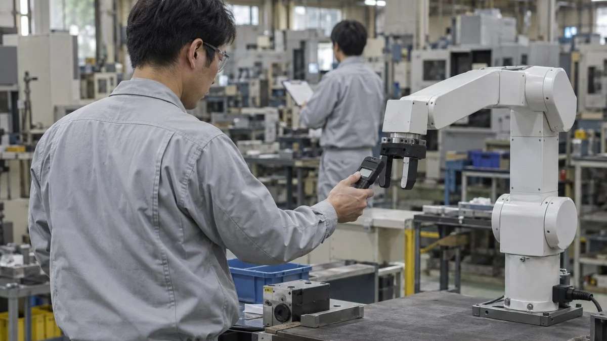
After installation, confirm that the real cell delivers the safety you designed. Cable routing and fixture positions always differ slightly from the drawings, so check again on the finished cell.
Figure 7 lists cobot-specific items to check before production.
Before production, confirm one by one that the assessment's assumptions hold on the real equipment.
These are general examples. Set the actual items from your risk assessment.
Running without a fence does not remove the need for teaching and inspection rules. Write procedures for teaching, restart, and maintenance, and train the people who do this work before production starts.
Common Cobot Deployment Failures and How to Avoid Them
Many failures come less from the technology than from doing things in the wrong order or leaving responsibilities unclear. Figure 8 lists common ones. All of them can be prevented before the order is placed.
Each fix is cheapest before the purchase order.
The last failure is the easiest to miss. Name an in-house owner for maintenance and changeovers at start-up.
The last one deserves attention. Easy changeover is a cobot's strength, but without someone on the floor who can use it, the robot ends up sitting idle.
Questions to Ask the Japanese Supplier or Integrator
When the robot, the cell, or the design comes from Japan, settle these points before you order. They map to the steps above.
- Rated output: What is the rated output of each drive motor? (Relevant to the 80 W rule only if the cell is also used in Japan.)
- Standards and editions: Which standards and editions was the robot or system assessed against: ISO 10218-1/-2:2011, ISO 10218-1/-2:2025, ISO/TS 15066:2016, or JIS B 8433:2015?
- Collaborative modes: Which collaborative modes does the design use, and where in the cycle?
- Contact limits: For power and force limiting, what force and pressure limits were used for each body region, and from which document?
- Risk assessment: Can we receive the risk assessment, including residual risks and the assumptions about layout, end effector, and parts?
- Documents: Who prepares the technical file and the declaration of conformity, and do they cover the whole system or only the robot?
- Installer: Who is responsible for the installation conditions, and is this stated in the contract?
- Verification: Will contact forces be measured on the installed cell, and will we receive the measurement report?
- Settings protection: How are safety settings (speed, force, zones) protected from unauthorized changes?
- Changes: Which changes (end effector, part, layout, program) does the supplier consider to require reassessment?
You can adapt this email to send the key questions in one message.
Subject: [Project name] Cobot cell: standards, risk assessment, and safety documents
Dear [Name],
We plan to run the [robot model] cell at our [location] plant as a collaborative application without a fence. Before we place the order, could you confirm the following?
- The standards and editions used for the robot and system assessment (for example, ISO 10218-1/-2:2011 or :2025, ISO/TS 15066:2016)
- The collaborative modes used, and the force and pressure limits applied for power and force limiting
- Whether you can provide the risk assessment, including residual risks and layout assumptions
- Which documents you will deliver (technical file, declaration of conformity, contact force measurement report) and whether they cover the full system
- Which changes to the end effector, parts, or layout would require a new assessment
We will review the answers with our safety team against the requirements that apply at our site.
Best regards,
[Your name]
Limits of This Guide
- This is an overview, not a compliance procedure. The regulations and standards that apply depend on the country and site, so confirm them with a qualified safety professional, the robot maker, and your integrator.
- The Japanese rules described here (the 80 W rule, Article 150-4, the 2013 notice, special education) apply to robots installed in Japan. Outside Japan, they only explain what Japanese documents mean.
- Examples such as the 500 mm separation come from a Japanese notice written for ISO 10218:2011. Check the criteria in the edition you work to.
- Standards change. ISO 10218 was revised in 2025, and national adoptions follow on different schedules, so check the current status before you rely on a specific edition.
FAQ
Is ISO/TS 15066 Still Used After the 2025 Revision?
Its content lives on in ISO 10218-2:2025, which consolidated most of ISO/TS 15066:2016, including the force and pressure limits for contact. Supplier documents written before 2025 may cite ISO/TS 15066, so check which edition a document is based on.
Does a Cobot Need a Risk Assessment?
Yes. The robot is only one part of the system, and the end effector, parts, layout, and people around it create their own hazards. A low-force robot with a gripper that handles sharp parts can still cause cuts.
What Is the 80 W Rule in Japan?
Under Japan's Ordinance on Industrial Safety and Health, machines whose drive motors are rated 80 W or less fall outside the industrial robot rules. For robots above 80 W, including many cobots, measures such as a fence are required when contact with the running robot could endanger workers. The 2013 MHLW notice sets the conditions for working without a fence, and outside Japan, local regulations apply instead.
What Changed in ISO 10218 in 2025?
The February 2025 revision folded most of ISO/TS 15066 into ISO 10218-2. It also framed safety around the collaborative application and added two robot classes, performance levels per safety function, and new requirements such as cybersecurity.
How Is a Cobot Different From a Conventional Industrial Robot?
A cobot is designed to work in the same space as people without a safety fence. Most models detect contact and stop or slow down when a person approaches, and they usually run with limited speed and force.
Sources
- 80 W rule, the two routes, technical file contents, points for risk estimation: MHLW leaflet on safety standards for human-robot collaboration, December 2013 (Japanese)
- 2013 notice text (80 W exclusion, teaching and inspection measures, special education): MHLW, partial revision of the enforcement notice for Article 150-4 of the Ordinance on Industrial Safety and Health, Kihatsu 1224 No. 2, December 24, 2013 (Japanese)
- Notes on the notice: MHLW, Kian-anpatsu 1224 No. 1, December 24, 2013 (Japanese)
- Risk reduction priority, records, and safety conditions in orders: MHLW, guideline on comprehensive safety standards for machinery (Japanese)
- Four modes of collaborative operation: JIS B 8433-1:2015 (ISO 10218-1:2011) (Japanese)
- JIS B 8433-2:2015 status: Japanese Standards Association, JSA Webdesk (Japanese)
- ISO 10218-1:2025 publication: Japanese Standards Association, JSA Webdesk (Japanese)
- TS B 0033:2017 withdrawal (March 25, 2025): Japanese Standards Association, JSA Webdesk (Japanese)
- ISO 10218:2025 key changes: ibf solutions, "New standards for industrial robots EN ISO 10218-1 and -2"; A3, "Updated ISO 10218: Answers to Frequently Asked Questions"; SICK, "More safety for humans and machines"
- ANSI/A3 R15.06-2025: Robotics & Automation News, "A3 releases new American National Standard for industrial robot safety" (September 15, 2025)
- Cobot share of installations: IFR, "How Robots Work alongside Humans" (December 4, 2024)
Original article in JapaneseThis guide is adapted from a MONOSCOPE article written for readers in Japan: 協働ロボットの導入手順|リスクアセスメントから立ち上げまで6ステップ
About the editor
 MONOSCOPE EditorFOUNDER & EDITOR
Spent about ten years at a plant equipment maker and a plant engineering company, proposing, designing, and commissioning equipment, then moved into web marketing. Now a web consultant for B2B manufacturers, helping them explain their products and technology. Licensed in Japan as an Energy Manager and a Third-Class Chief Electrical Engineer.
Has run an engineering blog since 2017 (500+ articles) and a Japanese YouTube channel with about 20,000 subscribers. Each English guide is written from the Japanese shop-floor point of view and checked against the cited standards.