Motorized Valve Actuator Current: VA vs W and Inrush
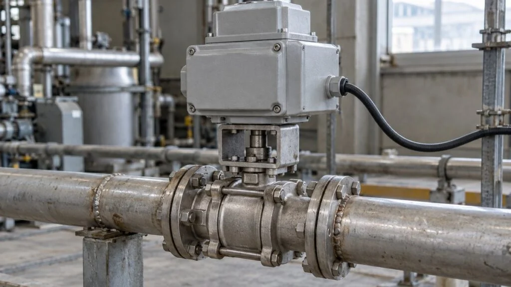
You open the datasheet for a Japanese electric valve actuator and find three numbers side by side: motor 20 W, 50 VA at rated output, and 100 VA at startup. You need a current figure to size the power supply, the breaker, and the control contacts.
None of those three numbers is a current. The two VA values can be converted to amps once you know the supply, but the watt value cannot be treated the same way.
The short answer: VA is apparent power, not current. To convert it to amps, you need the supply type (single-phase AC, three-phase AC, or DC), the supply voltage, and whether the value is for rated operation or startup. A single-phase 100 V, 50 VA rating works out to 0.50 A, but you cannot simply divide a watt figure (power consumption or motor output) by the voltage and get the same kind of answer.
This guide explains how to read each value, how to calculate current for single-phase, three-phase, and DC supplies, and how to keep rated, inrush, and locked-rotor current apart. It ends with a checklist and a sample inquiry you can send to a Japanese supplier.
Contents
- What a Motorized Valve Actuator Does
- Japanese Datasheet Terms for Actuator Current and Power
- VA vs. W: Three Different Numbers
- Calculating Current: Single-Phase, Three-Phase, and DC
- Rated, Inrush, and Locked-Rotor Current
- Sizing the Power Supply, Breaker, and Control Contacts
- Energy Consumption: Include Run Time and Standby
- Quick Reference: VA, W, and Motor W
- Checklist Before You Size the Supply
- Questions to Ask the Japanese Supplier
- Where This Guide Does Not Apply
- FAQ
- Sources
What a Motorized Valve Actuator Does
A motorized valve (電動弁, dendo-ben) is an automatic valve that opens and closes by turning its stem with an electric motor. It combines a valve body, which carries the process fluid, with an electric actuator mounted on top of it.
The actuator converts electrical energy into mechanical motion. Besides the motor, it contains a gear reducer that slows the rotation to produce the torque the valve needs, and a mechanism that stops the valve at the set position. Figure 1 shows how these parts connect.
Figure 1: The Actuator Takes Electrical Power; the Valve Body Carries the Fluid
Motor rotation passes through the gear reducer and shaft to the valve. Look at the power supply, the mechanical drive, and the process flow separately.
Functional schematic only. The internal layout and the stop and return mechanisms differ by model. Blue shows electrical power; brown shows mechanical rotation.
Actuators come in on/off types, which switch between fully open and fully closed, and modulating types, which move the valve to an intermediate position on command. A valve that can stop partway is not automatically suited to continuous control, so select the valve and the actuator as a matched pair.
Supply options include AC and DC, with ratings such as AC 100 V, AC 200 V, and DC 24 V. The starting point is to match the supply available at the installation site with the rating of the exact actuator you are ordering.
Two supplies with the same voltage number are not interchangeable if they differ in AC vs. DC, single-phase vs. three-phase, or frequency. Japan adds a twist: eastern Japan runs at 50 Hz, western Japan at 60 Hz, and standard outlets supply 100 V.
Some Japanese datasheets split values by voltage and frequency.
Motorized Valves vs. Solenoid Valves
A solenoid valve (電磁弁, denji-ben) moves its internal parts with the magnetic force produced by current in a coil. A motorized valve transmits motor rotation through a gear reducer instead. Because the drive principles differ, read the current values in each catalog according to its drive type.
Some solenoid valves move the valve directly with magnetic force, while pilot-operated types use the pressure difference across the valve. The name "solenoid valve" alone does not rule out large sizes or high pressures.
When a solenoid valve switches the operating air of an air-operated valve, the compressed air supplies the force that moves the main valve. That is how a small solenoid valve can operate a large main valve.
Opening and closing speed and the allowable differential pressure also depend on more than the drive type. Compare models on their stated application conditions, using the operating time you need and the torque the valve requires. In systems where rapid closing is a concern, do not choose a valve on speed alone.
Japanese Datasheet Terms for Actuator Current and Power
A Japanese actuator specification table typically lists supply voltage, power consumption, motor output, and rated current. Match each column name to its unit before you use any number. The table below shows labels you are likely to see.
| Japanese label | Romaji | Meaning | Unit |
|---|---|---|---|
| 電源電圧 | dengen den'atsu | Supply voltage | V |
| 単相 / 三相 | tanso / sanso | Single-phase / three-phase | – |
| 消費電力 | shohi denryoku | Power consumption (check whether W or VA) | W or VA |
| 皮相電力 | hiso denryoku | Apparent power | VA |
| 有効電力 | yuko denryoku | Active (real) power | W |
| モータ出力 / モータW | mota shutsuryoku / mota W | Motor output / motor wattage (often mechanical output; check the column definition and notes) | W |
| 定格電流 | teikaku denryu | Rated current | A |
| 定格出力時 | teikaku shutsuryoku-ji | At rated output | VA, A |
| 起動時 / 起動電流 | kido-ji / kido denryu | At startup / starting current | VA, A |
| 突入電流 | totsunyu denryu | Inrush current | A |
| 拘束電流 | kosoku denryu | Locked-rotor current | A |
| 呼び径 | yobi-kei | Nominal pipe size (for example, 50A) | Size designation, not an electrical unit |
Watch the last row. A valve listed as "50A" is a nominal pipe size in the millimeter series, not a 50-ampere current. If you pick numbers off a product table without their column labels, you can confuse the valve size with its electrical rating.
VA vs. W: Three Different Numbers
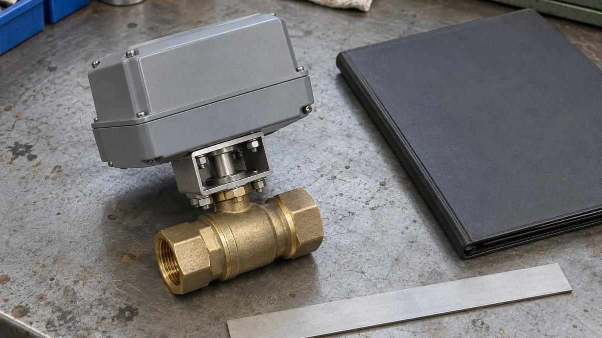
Current is measured in amperes (A) and voltage in volts (V). Power appears in two units on actuator datasheets: watts (W) and volt-amperes (VA). The watt figure itself can mean two different things, so an actuator table can hold three kinds of power value.
VA (Apparent Power): Divide by Voltage for Single-Phase AC
For single-phase AC, apparent power is the product of the RMS voltage and RMS current. With a fictional rating of single-phase 100 V and 50 VA, you divide 50 by 100 to get the current. The 50 VA by itself does not tell you how large the current is.
Figure 2: Two Fields to Read Before Converting 50 VA to Amps
Confirm the phase and voltage first, then use the apparent power for that condition.
The same 50 VA under a different condition, single-phase 200 V, gives 0.25 A. This does not mean you can apply a different voltage to the same actuator.
Written as a formula, the single-phase calculation looks like this.
W (Active Power): You Also Need the Power Factor
For single-phase AC, active power in watts equals voltage times current times the power factor. If the same 50 VA unit draws a fictional 30 W of active input, the power factor is 0.60. Reading 50 VA as 50 W erases that distinction.
Going the other way, a watt figure and a voltage are not enough. If the power factor is unknown, there is no single answer for the single-phase AC current.
Motor W (Output): Not Electrical Input at All
Motor output is the mechanical work the shaft delivers to the load. The input drawn from the supply also covers internal losses, so mechanical output and power consumption are different values. Both use the watt, which means the unit alone cannot tell you which one you are looking at.
Suppose one table lists "motor 20 W" and "50 VA at rated output." Dividing 20 by 50 to get a power factor would be premature: if 20 W is mechanical output, it is not active input. Figure 3 uses a published Japanese table to show how the columns differ.
Figure 3: W and VA Sit in Separate Columns on a Real Datasheet
Published values listed by Nihon KOSO for 3200R / 32A1RA, used to show what each column means.
Source: Nihon KOSO, "Electric actuators: torque and thrust list" (Japanese). One model's published values, not standard values for all motorized valves. No supply voltage or power factor is added here, because the table alone does not establish them.
Power factor is active power divided by apparent power and describes the voltage-current-power relationship on the supply side. Efficiency is mechanical output divided by electrical input and describes losses in the conversion to motion. Do not treat the two as interchangeable.
A higher valve torque requirement may call for a different actuator. However, the link between torque and current also depends on speed, the reducer, and the motor type, so doubling the valve size does not double the current.
The differential pressure across the valve and the seat resistance also add to the load. Two valves of the same nominal size cannot be compared unless their conditions match, so read the specification as a valve body and actuator combination.
Calculating Current: Single-Phase, Three-Phase, and DC
Do not apply the single-phase formula to a model that runs on three-phase power. For balanced, sinusoidal three-phase supply, apparent power is √3 times the line-to-line voltage times the line current. Do not confuse line-to-line voltage with phase voltage.
With a fictional rating of three-phase 200 V and 300 VA, the line current is about 0.87 A. This formula assumes identical conditions on every phase; equipment with imbalance or waveform distortion needs a separate evaluation.
In DC steady state, power is simply voltage times current. A fictional DC 24 V actuator with a 6 W input draws 0.25 A. This steady-state figure does not cover the startup current or the maximum current of any electronic circuits inside the actuator.
In practice, look first for a current value published by the manufacturer before you convert anything. If the tables are split by voltage or frequency, use the row for the exact model you are ordering, and do not borrow values from a row for a different supply.
Rated, Inrush, and Locked-Rotor Current
Rated current is the reference value for operation under the conditions the manufacturer specifies. A different current flows at startup, so if you size control devices or the power supply on rated current alone, you miss the startup condition.
Locked-rotor current relates to the state in which the motor is prevented from turning. Keep that state separate from a normal start, where the motor is still accelerating. Terms such as starting current and inrush current, and the conditions behind them, follow each manufacturer's own definitions.
Figure 4: Startup and Locked Rotor Are Different States, Even When Both Draw High Current
Rather than applying a fixed multiplier, first check which state the datasheet value describes.
The motor is beginning to turn. Datasheets may list a startup current or VA separately from steady operation.
The reference condition at the specified supply, load, and other conditions. Standby current while stopped is a separate value.
Current related to a state in which the motor cannot turn. Do not treat it as a state in which a normal start can continue.
Not a quantitative time waveform. Startup, locked-rotor, and instantaneous reversing values vary with motor type, voltage, and output, so use the specification for the target model.
Oriental Motor's FAQ on AC motor current also separates rated current from inrush current, instantaneous reversing current, and locked-rotor current. The ratios it lists vary with motor type and output, so do not apply one motor's multipliers to every motorized valve.
For products with electronic control circuits, the motor's characteristics alone do not set the input current. Read the conditions for the actuator as a whole, including the maximum current with control and protection circuits, the duty cycle, and the number of starts.
Inrush VA and holding VA in a solenoid valve catalog are also different from the rated and startup values of a motorized valve. CKD's glossary separates inrush and holding for AC solenoid valves, but you cannot use a solenoid's holding current as a motorized valve's current while stopped.
Sizing the Power Supply, Breaker, and Control Contacts
The circuit that powers the actuator and the circuit that sends the open/close command each have their own ratings. Use the equipment specifications and the wiring diagram to determine whether a controller output drives only the actuator's control input or switches the motor load directly.
For example, a contact marked 5 A cannot be assumed to switch a motor load based on that number alone. Check the load type and startup conditions, and match the application conditions specified for the controller against those specified for the valve.
Figure 5: One Valve's Rating vs. Conditions for Running Several
The total capacity of the drive supply and the conditions for the control outputs are separate checks.
Solid blue: drive power; dashed brown: control signal. Functional layout only; it does not show the actual number of wires, terminal connections, or whether circuits can be shared. Check each output and the group total against their own ratings.
When several valves operate at the same time, the sum of their rated currents is not enough information. Also tell whoever sizes the supply which valves can start together, because even short strokes create a startup load. A low average daily consumption and the instantaneous capacity you need are separate questions.
The same split between startup and running applies to breakers and protective relays. Oriental Motor's FAQ, for example, advises choosing a breaker that does not trip on the motor's inrush current. Ask the actuator manufacturer for its recommended breaker and wire size, and check them against your local electrical code.
Whether several control lines can share one contact also depends on the circuit the manufacturer specifies. The role of a built-in relay and the conditions for parallel operation are in the manufacturer's documentation; do not decide the wiring method from catalog current values alone.
When you replace a motorized valve or its actuator, carry over the pipe size and connection dimensions as well as the differential pressure, required torque, and operating time. A new actuator can change the supply voltage, current, control input, and position feedback, so compare the old and new models item by item.
If current has risen compared with before, do not jump straight to valve size or motor output as the cause. Look at the load and the operating conditions separately.
Some of the same reasoning applies to changes in pump current, but pump characteristics do not transfer directly to valve opening and closing loads.
Energy Consumption: Include Run Time and Standby
Sizing the supply and measuring how much electricity you use are separate tasks. Energy (kWh) is active power accumulated over time, so multiplying VA by installed hours does not give kWh. Separate the time the valve runs from the time it sits still.
Assume a constant active input of 30 W while operating and 20 strokes a day of 20 seconds each. Under these conditions the operating share is about 3.33 Wh per day. This only demonstrates the method; it does not represent the daily consumption of any real product.
Some models keep using power while stopped, for control circuits or heaters, so add that separately. Do not assume that a stopped valve draws 0 W, or that it draws its rated power all day. Total the energy from the equipment configuration and the operating records.
In plants with many motorized valves, simultaneous starts feed into supply capacity, while daily stroke counts and standby feed into energy use. Documents that keep these two apart make it easier for panel designers and equipment suppliers to work from the same conditions when you add equipment.
Quick Reference: VA, W, and Motor W
VA and the two kinds of W look similar but do different jobs. Use this table to decide what each datasheet column can be used for.
| Use | VA (apparent power) | W (active power) | W (motor output) |
|---|---|---|---|
| What it represents | Supply-side voltage × current | Supply-side power that does work | Mechanical work delivered by the shaft |
| Single-phase AC current | Divide by voltage | Divide by voltage and power factor | Do not use for current |
| Power factor | Denominator of P/S | Numerator of P/S | Not used |
| Energy (kWh) | Do not use directly | Multiply by operating time in hours (Wh); divide by 1,000 for kWh | Not used |
| What to check | Startup or rated? | Add standby separately? | Column definition and notes |
Checklist Before You Size the Supply
Run through these items with the datasheet in hand before you finalize the power supply, breaker, wiring, and control outputs.
- Exact model number of the valve and actuator combination
- Supply type: AC or DC, single-phase or three-phase, voltage, and frequency (50 Hz, 60 Hz, or both)
- Whether each power value is VA (apparent) or W, and whether a W value is electrical input or motor output
- Rated current at your voltage and frequency, taken from the matching row
- Startup (inrush) current or VA, and how long it lasts
- Locked-rotor current and the protection the actuator has against it
- Maximum current including control circuits, heaters, and other internal loads
- Standby power while stopped
- Duty cycle and allowable number of starts
- Number of valves that can start at the same time on one supply
- Control input type and the contact rating the actuator requires
- Recommended breaker and wire size, checked against your local electrical code
- For replacements: torque, operating time, differential pressure, control input, and position feedback of the old and new units
Questions to Ask the Japanese Supplier
A datasheet may not state the conditions behind every value. The sample inquiry below asks for the information you need in one message; edit the bracketed parts for your project.
Subject: Electrical data request for [model number] motorized valve
We plan to use [quantity] units of [valve and actuator model number] on a [single-phase / three-phase] [voltage] V, [frequency] Hz supply. To size the power supply, breakers, and control circuits, please confirm the following:
1. Rated current (A) at our voltage and frequency.
2. Whether the VA values on the datasheet (rated output and startup) are apparent power, and the voltage and frequency they apply to.
3. Whether "motor W" is mechanical output or electrical input, and the active power input (W) or power factor at rated operation.
4. Startup (inrush) current and its duration, and locked-rotor current.
5. Maximum current including control circuits, plus standby power and any heater load.
6. Duty cycle and allowable number of starts.
7. Required contact rating and recommended wiring for the control input, including whether several actuators can share one contact.
8. Recommended breaker rating and characteristic, and recommended wire size.Thank you for your support.
Where This Guide Does Not Apply
All calculations here use fictional values to show the method. They are not ratings for any real product, and the Figure 3 values belong to one published model only.
Datasheet terms such as starting current and inrush current are defined by each manufacturer, and actuators with electronic controls may not behave like a plain motor. Breaker selection, wire sizing, and protection settings are decided by the responsible electrical engineer under the applicable code, using the manufacturer's data.
FAQ
How Many Amps Does a 50 VA Motorized Valve Draw?
On single-phase 100 V it is 0.50 A, and on single-phase 200 V it is 0.25 A, but without the voltage and phase there is no single answer. Also confirm whether that 50 VA is a startup or rated value, and match it to the specification column for the model you are selecting.
Can I Divide the Wattage by the Voltage to Get Current?
For DC steady state, yes. For AC active power, you also need the power factor. If the listed W is mechanical motor output, it is not electrical input at all, so check what the column means first.
Is a Contact Rated Above the Actuator's Rated Current Good Enough?
Not based on the numbers alone. The contact must also suit the load type, supply conditions, and startup current. Check whether the contact switches only a control signal or the motor circuit itself.
Can I Swap Motorized Valves of the Same Pipe Size?
Not on size alone. Fluid conditions, differential pressure, required torque, and operating time still apply. Beyond the valve body, check the actuator's supply, control input, position feedback, and behavior on loss of power.
Does Catalog VA × 24 Hours Give Daily Energy Use?
No. VA is apparent power, so it cannot go straight into a kWh calculation. Use the active input and the actual operating time, and include standby loads such as control circuits and heaters.
Sources
- Motor W, VA at rated output, and VA at startup by model (3200R / 32A1RA: 20 W, 50 VA, 100 VA): Nihon KOSO, electric actuator torque and thrust list (Japanese)
- Rated, inrush, instantaneous reversing, and locked-rotor current; breaker selection: Oriental Motor, "I am trying to select a breaker to combine with an AC motor. What is the current value that flows through the motor?"
- AC inrush and holding VA and DC power consumption of solenoid valves: CKD, glossary of terms (Japanese)
- Electrical input, mechanical output, losses, and efficiency: Nidec, "What Is a Motor?" (Japanese)
- Single-phase and three-phase power calculations: Mitsubishi Electric, electrical basics course (Japanese)
- Three-phase power calculation with waveform distortion: HIOKI, PW4001 power calculation formulas (Japanese)
- Japan's 50 Hz / 60 Hz split and 100 V outlets: KEK (High Energy Accelerator Research Organization), "Japanese Electricity"
Original article in JapaneseThis guide is adapted from a MONOSCOPE article written for readers in Japan: 電動弁の電流値はどう読む?VA・Wと起動電流の違い、計算の条件
About the editor
 MONOSCOPE EditorFOUNDER & EDITOR
Spent about ten years at a plant equipment maker and a plant engineering company, proposing, designing, and commissioning equipment, then moved into web marketing. Now a web consultant for B2B manufacturers, helping them explain their products and technology. Licensed in Japan as an Energy Manager and a Third-Class Chief Electrical Engineer.
Has run an engineering blog since 2017 (500+ articles) and a Japanese YouTube channel with about 20,000 subscribers. Each English guide is written from the Japanese shop-floor point of view and checked against the cited standards.