UPS for Control Panels: Topologies, Sizing and Hold Time
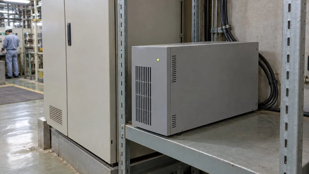
A machine arrives from Japan with a small UPS mounted inside its control panel. The label reads "AC100V," the manual calls it a joji shoyo kyuden unit, and your plant runs on 230 V at 50 Hz, or 120 V at 60 Hz. Or you are the one specifying the panel, and you need to decide which UPS goes in and how big it should be.
The short answer: pick the topology from what the load can tolerate, size the UPS so the load stays within both its VA and W ratings, and set the hold time from the shutdown sequence you actually need. Then check that the UPS input matches the local supply, because Japanese panels are often built around 100 V or 200 V.
This guide covers what a UPS does (and does not do) in a control panel, the three AC topologies, VA vs. W sizing, hold time, and Japan's 100 V/200 V and 50/60 Hz supply. It ends with a checklist and a list of questions to send the Japanese supplier.
A few Japanese terms show up on panel drawings and UPS manuals again and again:
- 無停電電源装置 (mu-teiden dengen sochi): uninterruptible power supply (UPS)
- 常時インバータ給電方式 (joji inverter kyuden hoshiki): online (double-conversion) UPS
- ラインインタラクティブ方式 (line-interactive hoshiki): line-interactive UPS
- 常時商用給電方式 (joji shoyo kyuden hoshiki): standby (offline) UPS; shoyo means commercial (utility) power
- 瞬停 (shuntei): momentary interruption; 瞬低, short for shunji den'atsu teika: momentary voltage sag
- バックアップ時間 (backup jikan): backup time, also called runtime or hold time
Contents
- What a UPS Does in a Control Panel (and What It Does Not)
- Two Jobs: Ride Through Disturbances and Buy Time to Shut Down
- The Three UPS Topologies: Online, Line-Interactive, and Standby
- Sizing a UPS for a Control Panel: VA, W, and Power Factor
- Hold Time: Reading the Runtime Curve
- Japan's Power Supply: 100 V/200 V and 50/60 Hz
- Exporting or Importing a Panel With a UPS Inside
- Checklist: Reviewing a UPS for a Control Panel
- Questions to Send the Japanese Supplier
- Limits of This Guide
- FAQ
- Sources
What a UPS Does in a Control Panel (and What It Does Not)
A UPS normally takes utility power, feeds the load, and keeps its battery charged. When the input fails or goes out of range, it keeps the output alive from stored energy. The battery is either built into the unit or housed in a separate battery cabinet, and sizes range from small desk-side units to large systems that support servers and critical plant equipment.
That stored energy is used in two ways. The UPS can carry the load until a generator starts, or it can keep equipment running long enough to shut it down in an orderly way before the battery runs out. In process plants, the protected loads are typically control and monitoring systems such as a distributed control system (DCS).
The key limit is scope. A UPS keeps alive only what is wired to its output. Keeping the control panel powered does not mean that pumps, motors, or network equipment fed from other circuits will keep running.
Figure 1 shows a typical split between the protected control circuit and the motor power circuit.
Figure 1: The UPS Protects the Control Circuit, Not the Motor Circuit
A conceptual example. The control panel and monitoring PC are fed from the UPS; the motor runs on a separate power circuit.
Signal wiring is omitted. Include network switches and field devices in the protected scope where the application needs them.
Even inside one panel, AC control power, DC power supplies, and network equipment may be on separate circuits. Mark the UPS output scope on the panel wiring drawings to catch protected loads that were missed.
The three topologies in this guide are AC-in, AC-out designs. If your controls run on 24 V DC, decide whether the AC UPS feeds a DC power supply or whether you back up the DC side directly. Either way, list the voltage and current needed and which device receives the power-fail and shutdown signals.
Two Jobs: Ride Through Disturbances and Buy Time to Shut Down
A UPS in a control panel does one of two jobs, or both. It rides through short power disturbances so the process keeps running, or it buys time during a long outage so data can be saved and equipment can stop safely. Keeping the process running and stopping it in a controlled way call for different protected loads and different hold times.
Riding Through Sags and Momentary Interruptions
A voltage sag (shunji den'atsu teika) is a short dip in voltage that does not necessarily reach zero; a momentary interruption (shuntei) is a brief loss of supply. Lightning-related grid faults and large loads starting up can cause either one, and even these short events can trip control equipment. To the load, a broken wire, a pulled plug, or a tripped protective device is also a power failure.
The UPS monitors its input. When the input moves outside the range set for that model, it switches to battery or otherwise keeps the output within limits.
Keep two specifications apart:
- Transfer time (milliseconds): how long the output is interrupted when the UPS switches to battery. It decides whether the load survives the switchover.
- Hold time (seconds to minutes): how long the battery can carry the load. It decides whether there is enough energy to finish saving data and shutting down.
A fast transfer is useless if a worn battery cannot hold the load long enough. A large battery is just as useless if the transfer gap is longer than the load can tolerate, because the controls drop out at the moment of transfer. Match the output voltage, frequency, and waveform to the input specification of the connected equipment.
Noise on power lines and noise on signal lines need different fixes in different places. Decide the role and placement of noise filters and combine them with the UPS's power conversion.
A fault upstream and a short circuit on the UPS output also call for different protection. Across the whole supply system, map which device isolates which fault, including molded case circuit breakers (MCCBs) and earth-leakage circuit breakers.
Protecting Production Data
Production equipment logs measurements, alarm history, and process conditions to a computer. If power drops suddenly, files or databases being written can be corrupted, and the last records before the stop may be lost.
Keeping the logging equipment on the UPS gives time to save data and close applications. Connecting a PC to a UPS does not make it save data automatically. Shutdown software, a network or serial link, or dry-contact signals must tell the PC to act, and the shutdown sequence (what to save, which services to stop) is part of the power design.
Protecting only the monitoring PC is not enough if the network switch goes down, because data from other devices will no longer arrive. If logging must continue, trace the full path: measurement, control, network, and storage.
Some designs pass UPS status signals, such as "on battery" and "battery low," to the controller as dry contacts. Agree on the direction and meaning of each signal so the controller knows what it can detect during an outage.
Figure 2 shows the order of events from the power failure to a completed shutdown.
Figure 2: Finish Saving and Shutting Down While Battery Remains
An example sequence. Column widths do not represent the time each step takes.
The order of equipment stop and data saving depends on the process. Transfer time (ms) and the hold time shown here (seconds to minutes) are separate specifications.
Moving equipment to a safe state takes more than power. It takes defined stop conditions and a stop sequence, so decide together with the interlock design which outputs stay on and which are released when power is lost.
For example, the controller may stay powered, but if the solenoid valves or instrument air that operate the valves are unavailable, the intended action may not be completed. Check the UPS scope and the state the equipment moves to during an outage as two separate questions.
A UPS does not replace data backup. Copy saved data to separate media as well, since a UPS protects against power loss but not against hardware failure or operator error.
Recovery needs its own design. The UPS output coming back, the PC rebooting, and the equipment restarting are three separate events. Define the required battery charge and the restart order, and make sure outputs that were on before the outage do not restart unexpectedly.
The Three UPS Topologies: Online, Line-Interactive, and Standby
AC UPSs come in three main topologies. In Japanese they are joji inverter (online), line-interactive, and joji shoyo (standby). IEC 62040-3, the UPS performance standard (Japan's counterpart is JIS C 4411-3), classifies UPSs by how their output depends on the input, and the three topologies usually fall into these classes:
- VFI (voltage and frequency independent): online, double-conversion UPS
- VI (voltage independent): line-interactive UPS
- VFD (voltage and frequency dependent): standby (offline) UPS
All three charge the battery and supply the load during a power failure. They differ in the normal power path, in how they regulate voltage, in transfer time to battery, and in losses and heat.
One unit can also change class with its operating mode. Schneider Electric notes that a double-conversion UPS in a high-efficiency (eco) mode may perform as VFD, so check the class for the mode you will run.
Online (Double-Conversion) UPS
An online UPS converts the incoming AC to DC even in normal operation, then rebuilds AC with an inverter. The load is always fed from the inverter, and the battery sits on the DC side.
Figure 3: An Online UPS Rebuilds the Output Even in Normal Operation
The normal path is rectifier, DC bus, and inverter. On battery, the same output inverter keeps running.
Battery charge/discharge and protection circuits are simplified. In bypass, power does not pass through the normal conversion path, and the protection the UPS provides changes.
When the input fails, the DC side draws from the battery and the same inverter keeps the AC output running. Because the power path does not switch, there is no break when the UPS moves from normal operation to battery.
Online units regulate output voltage and frequency well, which is why they serve servers and control equipment with strict power-quality needs. To see how far a given unit isolates the load from input disturbances, check its datasheet values, such as input voltage range and output regulation.
Because they convert power all the time, online units have conversion losses and produce more heat. Choose the mounting location based on panel temperature and the airflow path, and leave the clearances the maker requires for cooling and maintenance.
Some models include a bypass that feeds utility power straight to the output during overloads or internal faults. In bypass, the inverter is not rebuilding the output, so do not assume the load has the same protection as in normal operation.
"No break on transfer to battery" is not the same as "no break under every fault." Treat the switch to battery separately from the transfer conditions during faults and maintenance. Depending on what must stay up during a fault, consider redundancy or a maintenance bypass.
Line-Interactive UPS
A line-interactive UPS feeds the load through the utility path in normal operation and corrects voltage swings with an automatic voltage regulator (AVR). When the input voltage rises or falls, the AVR adjusts the output, for example by switching transformer taps.
Figure 4: Voltage Correction in Normal Operation vs. Battery Supply in an Outage
A conceptual AVR using autotransformer taps. The input and output share a common line, so this is not an isolated design.
Charging path and control circuits omitted. AVR correction in normal operation and the move to battery are separate actions.
Within the AVR's range, the UPS corrects voltage without drawing on the battery. When the input goes outside the usable range or fails, it transfers the load from the utility path to the battery and inverter.
That transfer takes time, so compare it with the interruption the load can tolerate. Figures such as "a few milliseconds" are model-specific datasheet values, not numbers that apply to every unit.
Compared with a standby unit, a line-interactive UPS adds voltage regulation in normal operation, and it is used for servers and peripherals. Output waveform and noise suppression depend on the individual design, so do not assume that "line-interactive" automatically means "no noise filtering."
If input swings often exceed the AVR's range, the UPS will keep cycling to battery. When comparing topologies, measured voltage variation at the site and the frequency of disturbances are useful inputs.
Standby (Offline) UPS
A standby UPS passes utility power to the load in normal operation while charging the battery. When it detects a power failure or another input fault, it switches the load to the battery through an inverter.
Figure 5: A Standby UPS Switches the Output on an Input Fault
A functional sketch of the transfer switch. It does not show the actual relay or semiconductor switch.
Shows the utility path used in normal operation and the battery path used on a fault. Check each model's output waveform and protection features separately.
Because there is no continuous inverter conversion, a standby UPS draws little power internally. Many models are small and light, and they are used for PCs and peripherals where the supply is stable.
There is a transfer time between the input fault and battery operation. Choose the unit by comparing that transfer time with the interruption the load can tolerate.
On battery, some models output a sine wave and others a square wave. Match the waveform to what the load's power supply needs. A unit with enough capacity can still be the wrong choice if its waveform does not suit the load.
Omron, for example, states that its square-wave models must not be used with PCs or servers that have power factor correction (PFC) power supplies, or with inductive loads such as coils and motors.
Loads such as motors and transformers, and loads with high inrush current, need a check against the maker's connection conditions. Connecting plant motor loads to a small general-purpose UPS is a separate design question from protecting the control power.
Figure 6 puts the three topologies side by side.
Figure 6: Normal Path, Transfer, and Voltage Regulation Compared
Typical characteristics only. Confirm waveform, transfer time, and bypass features on each model's datasheet.
| Item | Online (double conversion) | Line-interactive | Standby (offline) |
|---|---|---|---|
| Japanese name | Joji inverter kyuden | Line-interactive | Joji shoyo kyuden |
| Typical IEC 62040-3 class | VFI | VI | VFD |
| Normal power path | Through rectifier and inverter | Utility path plus AVR | Utility path |
| Transfer to battery | No break from normal operation | Has a transfer time | Has a transfer time |
| Voltage regulation in normal operation | Inverter builds the output | AVR within its range | Follows the utility input |
| What to check | Output quality, losses, heat, bypass behavior | AVR range, transfer time, how often input swings | Transfer time, output waveform, site supply quality |
IEC class mapping per Schneider Electric White Paper 1. A unit's class can change with its operating mode (for example, eco mode).
Sizing a UPS for a Control Panel: VA, W, and Power Factor
A UPS output rating gives two numbers: apparent power in volt-amperes (VA) and real power in watts (W). The connected load must stay within both ratings. A large VA rating alone is not enough, and Omron notes that exceeding either one triggers the overload alarm.
The W rating is usually lower than the VA rating, and the ratio is the UPS's output power factor. Schneider Electric explains that the W rating has traditionally been about 60% of VA, and that newer models have W and VA ratings closer together. Never assume a ratio; read both numbers on the datasheet.
As a worked example, assume three loads: a controller at 120 W / 150 VA, a monitoring PC at 180 W / 225 VA, and a network switch at 40 W / 50 VA. These are made-up values for the calculation. For a real selection, use each device's maximum power consumption from its datasheet.
Now suppose you pick a hypothetical UPS rated 1,000 VA / 300 W. The VA rating has plenty of headroom, but the 340 W load already exceeds the 300 W rating. Check the load list against both ratings every time.
The margin also covers future additions and load variation. Even within the ratings, inrush current at startup can overload the UPS, so evaluate steady-state consumption and momentary peaks separately.
Hold Time: Reading the Runtime Curve
Backup time for the same UPS changes with the load in watts. Apply your actual load to the maker's runtime table or curve, and confirm that it covers the time needed to save data and shut down.
Multiplying battery voltage by amp-hours (V × Ah) gives a rough idea of the stored energy. Actual hold time also depends on discharge conditions, conversion losses, and end-of-discharge voltage, so dividing that energy by the load in watts does not tell you how a given model will perform.
Build up the required time from the steps that must happen: waiting for the power-fail detection, saving records, stopping equipment, and shutting down the OS. Do not just pick a fixed number such as 10 minutes. Include the time those steps take under heavy processing, plus a margin before the end.
Battery aging and ambient temperature both cut into the available time. Fuji Electric, for example, recommends choosing at least twice the required backup time, and states that at the end of battery life, backup time falls to half the initial value. Size the margin so the UPS still covers the required time right up to the scheduled battery replacement.
Heat inside the panel, blocked airflow, and a hot mounting location all shorten battery and UPS life. Set the battery replacement interval from the battery type and the model's temperature conditions.
On the UPS output, the available short-circuit current differs between inverter operation and bypass. Compare the UPS's short-circuit and overload characteristics with the trip characteristics of the circuit protectors and fuses, and design the branch layout and protection coordination around both modes.
In maintenance, review the alarm history, battery condition, load changes, and required hold time at regular intervals. Waiting for a real outage is a poor way to find a weak battery, so combine the model's self-test functions with a planned test whose impact on the process is controlled.
Japan's Power Supply: 100 V/200 V and 50/60 Hz
Japan's low-voltage supply differs from the US, India, and most of Southeast Asia, and it shows up directly on UPS nameplates. The standard outlet voltage is 100 V, and many buildings use a single-phase three-wire system (tanso sansen-shiki) that provides 100 V line-to-neutral and 200 V line-to-line. Factories also use three-phase 200 V, and a panel fed from 200 V may use a control transformer to step down to 100 V for its control circuits.
Frequency is split by region. Eastern Japan uses 50 Hz and western Japan uses 60 Hz, with the boundary running roughly from the Fuji River in Shizuoka to the Itoigawa area in Niigata. Because the Fuji River divides Shizuoka Prefecture itself, the line does not follow prefectural borders, so confirm the frequency for the specific plant rather than the prefecture.
The table compares the nominal outlet supply in Japan with common destinations for Japanese equipment.
| Country | Nominal voltage (single-phase outlet) | Frequency |
|---|---|---|
| Japan | 100 V | 50 Hz (east) / 60 Hz (west) |
| United States | 120 V | 60 Hz |
| India | 230 V | 50 Hz |
| Thailand, Vietnam, Indonesia | 230 V | 50 Hz |
| Malaysia | 230 V (often about 240 V in practice) | 50 Hz |
| Philippines | 230 V | 60 Hz |
Here is what that means for a UPS in a Japanese panel:
- Input voltage: a UPS rated "AC100V" is built for Japan's 100 V. On a 120 V or 230 V supply, it needs a step-down transformer to 100 V, or a replacement rated for the local voltage. A 100 V output also has to match the panel's control voltage.
- Input frequency: Japanese UPS datasheets list a rated input frequency, for example "50/60 Hz ±4 Hz." Check that the range covers your site's frequency and how the unit selects it.
- Output frequency on battery: the inverter output frequency must match what the loads expect. Ask the supplier how the unit sets its output frequency.
- Input voltage window: the range in which the UPS stays on utility power is set around the nominal voltage. A window built around 100 V does not carry over to a different supply, and on a weak local grid even a correctly rated UPS may cycle to battery often.
Exporting or Importing a Panel With a UPS Inside
When a panel built in Japan is shipped to a site abroad, the UPS needs its own review. Topology and capacity are only part of it. Settle the points below before the panel ships.
- Voltage strategy: keep the Japanese 100 V UPS and add a step-down transformer upstream, or replace it with a UPS rated for the local voltage. Either way, the downstream control voltage must stay what the panel was designed for.
- Safety certification: the destination may require a specific listing or marking. In the US and Canada, the UPS safety standard is UL 1778 (harmonized with CSA C22.2 No. 107.3). The IEC safety standard is IEC 62040-1. Which approval is required, and whether a UPS inside a listed panel needs its own listing, is for the panel's certifying engineer and the local authority to decide.
- Performance specification: if your spec calls for an IEC 62040-3 class (VFI, VI, or VFD), ask the supplier to state the class of the unit and the operating mode it applies to.
- Battery: confirm the battery type, the expected replacement interval at your site temperature, and whether replacement batteries can be bought locally.
- Shutdown signals: confirm the interface (dry contacts, serial, or network card), the signal meanings, and whether the shutdown software and manuals are available in English.
- Documentation: UPS manuals, alarm messages, and labels may be in Japanese only. Request English versions before shipment.
Checklist: Reviewing a UPS for a Control Panel
Use this list when you review a panel design or a Japanese supplier's UPS proposal.
- Purpose: ride-through only, orderly shutdown, or both
- Protected scope: every load on the UPS output listed (controller, HMI/PC, network switches, field devices); loads that will stop during an outage identified
- Topology: online, line-interactive, or standby; IEC 62040-3 class and the operating mode it applies to
- Transfer time: datasheet value compared with what each load can tolerate
- Output waveform: sine or square wave on battery; suitable for PFC power supplies and inductive loads
- Capacity: total load within both the VA and W ratings, with margin; inrush current checked
- Hold time: built up from the shutdown sequence; checked on the runtime curve at the actual load; margin for battery aging and temperature
- Supply: UPS input voltage and frequency range match the site supply; output voltage matches the panel control voltage
- Bypass: when the UPS goes to bypass, what protection is lost, and whether a maintenance bypass is needed
- Protection: short-circuit current in inverter and bypass modes coordinated with downstream protective devices
- Signals and software: on-battery and low-battery signals wired and defined; shutdown software configured and tested
- Recovery: restart order and conditions after power returns; no unintended restart of outputs
- Heat and maintenance: mounting location, clearances, battery replacement interval, self-test plan
- Certification and documents: required listing or marking for the destination; English manuals and labels
Questions to Send the Japanese Supplier
These questions can be copied into an email or a technical query sheet as they are.
- Please provide the UPS maker, model number, and datasheet. Is it online (joji inverter), line-interactive, or standby (joji shoyo)?
- What are the UPS input voltage and frequency ranges? Can the unit operate on our site supply of [voltage] V, [frequency] Hz? If not, what do you propose (transformer or a locally rated UPS)?
- Please list every load connected to the UPS output with its W and VA values, and show the total against the UPS ratings.
- What hold time did you design for, and at what load? Please show the shutdown steps it covers and the runtime curve you used.
- What is the transfer time to battery, and what is the output waveform on battery?
- Under what conditions does the UPS go to bypass, and what happens to the load in bypass?
- Which UPS status signals are wired to the PLC or PC, and what does each signal mean? Is shutdown software included and configured?
- What is the battery type and recommended replacement interval? Can replacement batteries be sourced outside Japan?
- Which safety certification does the UPS carry (for example, UL 1778 or IEC 62040-1)? Are English manuals available?
Limits of This Guide
- This guide focuses on AC UPS units for control power. Large three-phase systems and DC UPSs follow the same ideas but need the maker's own design guidance.
- Transfer times, waveforms, input ranges, and runtimes vary by model. Always use the datasheet of the specific unit.
- The sizing figures and the 20% margin are illustrations, not design rules. Your company or project may set its own margin.
- Voltages in the country table are nominal outlet values. Industrial supplies and actual voltages at your site may differ.
- Which certification a UPS needs, and how the panel must behave on power loss, depends on the project specification, applicable codes, and the safety design. Those decisions belong to the responsible engineer and the local authority.
FAQ
Will a UPS Keep My Whole Machine Running?
No. It keeps running only the equipment wired to its output, and only for as long as the battery lasts. If motor power, instrument air, or networks on other circuits stop, the process may not be able to continue, so decide in the design which equipment keeps running and which stops.
Does an Online UPS Stay Uninterrupted Under Every Fault?
No. An online UPS has no break when it moves from normal inverter operation to battery. Internal faults, overloads, and bypass or maintenance operation are different conditions, so read each model's operating specification for those cases too.
Online vs. Line-Interactive UPS: Which Should I Use for a Control Panel?
It depends on the load and the site supply. Choose online when the load cannot tolerate any transfer gap or the supply has frequent voltage and frequency disturbances. A line-interactive unit can be enough when the load tolerates the datasheet transfer time and the input usually stays within the AVR's range.
Does a Bigger UPS Run Longer?
Not necessarily. The output rating in VA and W and the battery hold time are separate performance values. Two UPSs with the same rating can have different hold times depending on the battery, so pick the unit from the runtime table at your load in watts.
Can a UPS Save My Data Automatically?
Not by itself. A UPS only supplies power, so it needs shutdown software or network or contact signals to tell the applications and OS to close while battery power remains. After power returns, battery recharge is not instant, so define the restart order and conditions as well.
Sources
- UPS topologies, IEC 62040-3 input-dependency classes (VFD, VI, VFI), class change in eco mode: Schneider Electric, White Paper 1 "The Different Types of UPS Systems"
- VA vs. W ratings and the traditional 60% ratio: Schneider Electric FAQ FA157485; Schneider Electric blog, "VA vs Watts: What's the Difference Anyway?"
- AVR voltage regulation vs. battery operation: Schneider Electric FAQ FA158913
- Protection coordination downstream of a UPS: Schneider Electric FAQ FAQ000280512
- Japanese UPS topologies and output waveforms: Omron Social Solutions, UPS power supply methods (Japanese)
- VA/W limits, transfer time, square-wave restrictions, backup-time conditions: Omron Social Solutions, specification glossary (Japanese)
- Restart after power returns: Omron Social Solutions FAQ (Japanese); Schneider Electric FAQ FA342238 (Japanese)
- UPS overview and shutdown software: Omron Industrial Automation, UPS technical guide (Japanese); shutdown software (Japanese)
- Backup-time margin (2x) and halving at end of battery life: Fuji Electric, how to select a UPS (Japanese)
- Power disturbances, topologies, and bypass: Mitsubishi Electric, UPS product features (Japanese)
- Momentary voltage sags: Kansai Transmission and Distribution (Japanese)
- AVR with autotransformer taps (principle of Figure 4): Renesas, application note CM-314
- JIS C 4411-3:2014 (counterpart of IEC 62040-3): Japanese Standards Association preview (Japanese); IEC 62040-3:2021: IEC Webstore
- IEC 62040-1 (UPS safety requirements): IEC Webstore
- UL 1778 scope and harmonization with CSA C22.2 No. 107.3: UL Solutions, "UL 1778, the Standard for Uninterruptible Power Systems"
- Nominal voltage and frequency by country: WorldStandards, "Plug, socket and voltage by country"
- 50/60 Hz boundary in Japan: Hitachi Energy, interregional HVDC interconnection in Japan (Japanese)
- Single-phase three-wire 100/200 V system: Watanabe building services glossary
Original article in JapaneseThis guide is adapted from a MONOSCOPE article written for readers in Japan: UPSとは?制御盤の無停電電源装置の役割・3方式と容量の選び方
About the editor
 MONOSCOPE EditorFOUNDER & EDITOR
Spent about ten years at a plant equipment maker and a plant engineering company, proposing, designing, and commissioning equipment, then moved into web marketing. Now a web consultant for B2B manufacturers, helping them explain their products and technology. Licensed in Japan as an Energy Manager and a Third-Class Chief Electrical Engineer.
Has run an engineering blog since 2017 (500+ articles) and a Japanese YouTube channel with about 20,000 subscribers. Each English guide is written from the Japanese shop-floor point of view and checked against the cited standards.