Voltage Drop and Cable Sizing: Reading Japanese Formulas

A Japanese contractor sends the cable calculation sheet for a new production line. One column is headed 電圧降下 (den'atsu koka, "voltage drop"), and every row uses the same formula: e = 30.8 × L × I ÷ (1000 × A). The cables are 5.5, 8, and 14 mm², each circuit is marked "2% or less," and your project specification cites the NEC or IEC 60364.
The numbers are not mysterious. The coefficients 35.6, 30.8, and 17.8 come from the resistance of copper wire, and the 2% limit comes from a Japanese wiring code. Once you know the assumptions behind them, you can check the sheet against your own method and limits.
This guide explains what voltage drop is and why it matters, how to read the Japanese simplified formula, how it lines up with NEC and IEC practice, how Japanese cable sizes compare with IEC and AWG sizes, and what to ask the Japanese side before you accept a cable size. Final design decisions belong to a qualified engineer working to the codes that apply at your site.
Contents
- What Is Voltage Drop?
- Four Factors That Increase Voltage Drop
- Equipment Problems Caused by Voltage Drop
- How to Read the Japanese Simplified Formula
- Japanese Formula vs. NEC and IEC Methods
- Allowable Voltage Drop: Japan vs. IEC vs. NEC
- Cable Sizes: Japanese mm², IEC mm², and AWG
- How a Japanese Sizing Sheet Is Usually Built
- Ways to Reduce Voltage Drop
- Checklist: Reviewing a Japanese Voltage Drop Calculation
- Questions to Ask the Japanese Side
- Where This Guide Does Not Apply
- Frequently Asked Questions
- Sources
What Is Voltage Drop?
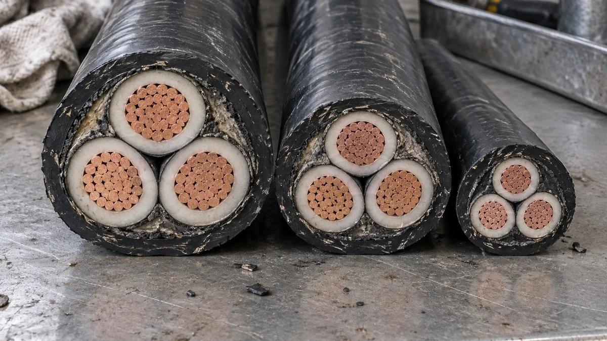
Even copper and aluminum conductors have some resistance. When current flows, Ohm's law says a voltage equal to current × conductor resistance is used up along the cable, so the voltage at the load terminals is lower than at the source.
A Japanese government technical reference on electrical installations (Ministry of Agriculture, Forestry and Fisheries) defines voltage drop as the fall in voltage between the supply point and the point of use, caused by conductor resistance and reactance. Reactance is the property that opposes changes in current in an AC circuit.
The lost voltage multiplied by the current turns into heat in the cable. That heat is wiring loss.
Current flows out on one conductor and back on the other, and each conductor's resistance uses up a little voltage.
Example values for a 2% (4 V) drop. In three-phase circuits, the number of conductors and the coefficient change (see Figure 5).
The same thing happens with a long extension cord. Hataya, a Japanese extension cord maker, gives an example in which 5 A through a 20 m cord with 0.75 mm² conductors drops about 4.7 V, so 100 V at the outlet becomes about 95.3 V at the far end.
Four Factors That Increase Voltage Drop
Voltage drop is the product of conductor resistance and current. Resistance rises as a cable gets longer and thinner, and AC circuits add reactance and power factor, so the causes fall into four groups.
If any one of them gets worse, the voltage reaching the load falls.
The Ministry of Agriculture, Forestry and Fisheries reference lists the causes as resistance, reactance, current, and power factor.
Longer, Smaller Conductors Have More Resistance
Conductor resistance is proportional to length and inversely proportional to cross-sectional area. Doubling the length doubles the resistance, and so does halving the area, so the farther the load and the smaller the cable, the larger the drop.
A Japanese catalog for 600 V CV cable (XLPE-insulated, PVC-sheathed power cable) shows the scale. For three-core cable, the maximum conductor resistance at 20°C (68°F) is 2.36 Ω/km for 8 mm² and 1.34 Ω/km for 14 mm². Going up one size cuts the resistance to about 60%.
Higher Current Means a Larger Drop
On the same cable, doubling the current doubles the voltage drop. That is why a circuit that worked fine can start showing low voltage after new equipment is added to it.
Motor starting needs special attention, because a squirrel-cage induction motor draws a large current for a short time when it starts. Japanese references call this 瞬時電圧降下 (shunji den'atsu koka, momentary voltage drop) and treat it separately from the steady-state drop during normal running.
Power Factor and Reactance Also Matter
In AC wiring, reactance lowers the voltage along with resistance. With loads such as motors, where the current lags the voltage, the reactive component adds to the drop. The same current can therefore cause a larger drop than it would in a DC circuit.
Larger cables have lower resistance, but their reactance falls much less. On large feeders, power factor therefore has a noticeable effect.
Equipment Problems Caused by Voltage Drop
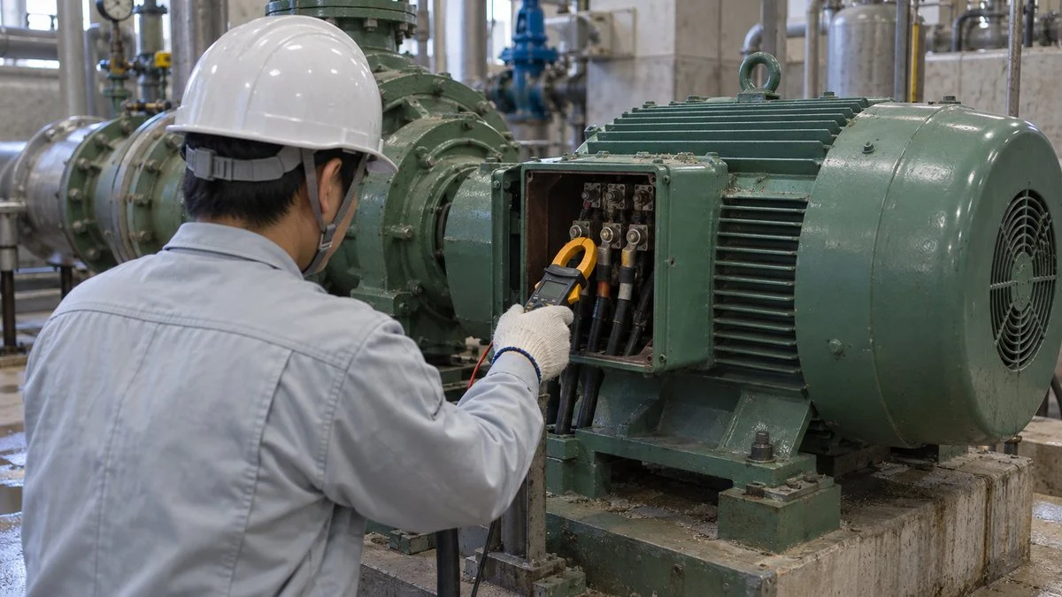
When the terminal voltage falls, equipment cannot deliver its rated performance. The Ministry of Agriculture, Forestry and Fisheries reference lists the effects by equipment type. The ones most relevant to factories are shown below.
Equipment stopping, motors failing to turn, and flickering lights are the symptoms people notice first.
Based on Table 7.1-8 in the Ministry of Agriculture, Forestry and Fisheries reference (in Japanese).
Motors are particularly affected. Oriental Motor explains that motor torque is approximately proportional to the square of the input voltage. By that relationship, a 10% voltage drop leaves only about 81% of the torque, so a heavily loaded machine may not reach speed and will draw more current.
The Utility Supply Voltage in Japan Also Varies
If the equipment will run in Japan, start from the utility voltage. Under Article 26 of the Electricity Business Act and Article 38 of its Enforcement Regulation, utilities must keep low-voltage supply within 101 V ±6 V on 100 V systems and 202 V ±20 V on 200 V systems. On a 200 V system, the voltage at the supply point can therefore be as low as 182 V.
The drop inside the plant comes on top of that. At a plant where the incoming voltage runs low, a long cable can push the terminal voltage below what the equipment accepts, so look at both together.
Steady-State Drop, Starting Dip, and Flicker
When voltage drop is suspected, the timing of the dip is the first clue. Low voltage all through operation points to cable length or size, a dip only at start-up points to starting current, and short repeating swings point to flicker (frequent voltage fluctuation that makes lights flicker).
Compare the voltage at the supply end and at the load at the same time, then sort by when the difference appears.
If the incoming voltage itself is low, the cause may be on the utility side rather than in the plant wiring. Measurements on live equipment should be made by qualified personnel under site safety rules.
For momentary dips at start-up, a starting method that limits inrush current helps.
How to Read the Japanese Simplified Formula
Japanese calculation sheets use one of two formulas: a 簡易式 (kan'i-shiki, simplified formula) for quick estimates, and a 基本式 (kihon-shiki, basic formula) that includes power factor and reactance. In practice, the simplified formula is used to estimate branch circuits, and the basic formula is used for a closer look at large feeders and motor loads.
The Coefficient Depends on the Wiring System
In a single-phase 2-wire circuit, current flows out on one conductor and back on the other, so the drop is twice the drop in one conductor. In a three-phase 3-wire circuit, the drop is measured line to line, so the factor is √3 (about 1.73).
Japan also uses single-phase 3-wire systems that carry 100 V and 200 V on one set of conductors, similar to North American 120/240 V split-phase service. Between a line conductor and the neutral, the factor is 1, because no current flows in the neutral when the loads are balanced.
The coefficient changes with the system, and the numbers in the simplified formula follow from it.
(単相2線式)
(単相3線式)
(三相3線式)
e: voltage drop [V]; L: route length, one way (こう長, kocho) [m]; I: current [A]; A: conductor cross-section [mm²]. The simplified formula assumes copper at 97% conductivity, power factor 1, no reactance, the load concentrated at the far end, and balanced phases (three-phase and single-phase 3-wire). Basic formula: e = K × I × (R cos θ + X sin θ) × L, with R and X per km and L in km.
Where 17.8, 35.6, and 30.8 Come From
The 17.8 is the resistance, in ohms, of 1 km of 1 mm² copper conductor at 97% conductivity. Annealed copper at 100% IACS (International Annealed Copper Standard) has a resistivity of 1/58 Ω·mm²/m at 20°C. Dividing by 0.97 gives about 0.0178 Ω·mm²/m, or 17.8 Ω per km for 1 mm².
Multiply 17.8 by the single-phase factor of 2 and you get 35.6. Multiply it by √3 and you get 30.8. Each formula is simply "resistance of one conductor × coefficient × current," rewritten.
L Is the One-Way Length
Japanese sheets label the length こう長 (kocho), the one-way route length from the source to the load. The return path is already built into the coefficient. Entering the round-trip length doubles the result and leads to an oversized cable.
The US K-factor formula works the same way: its L is also the one-way length, and the factor of 2 or 1.732 covers the return path.
Assumptions Behind the Simplified Formula
The simplified formula assumes power factor 1 and ignores reactance. On large feeders that mainly supply motors, it gives a lower value than the actual drop. One Japanese electrical supplier's guide notes that the simplified formula can come out about 20% lower than the basic formula and recommends the basic formula for feeders.
The basic formula uses the AC conductor resistance R and reactance X per km from the cable manufacturer's catalog, plus the load power factor cos θ. Typical power factors used are 0.8–1.0 for lighting and about 0.75–0.8 for motor loads. When loads are tapped off along the run, each section is calculated separately and the results are added.
Japanese Formula vs. NEC and IEC Methods
The three methods share the same physics: current × resistance (plus reactance) × a coefficient for the wiring system. They differ mainly in units, conductor temperature, and how the resistance figure is chosen.
Same structure, different units and resistance basis.
Converted to metric units, K = 12.9 Ω·cmil/ft is about 21.4 Ω·mm²/km, roughly 20% higher than the 17.8 used in the Japanese formula. For the same circuit, the US formula therefore gives a larger drop.
That difference matters when you compare results. A Japanese sheet that shows a circuit just inside 2% may land at or slightly above that limit when you recalculate it with a 75°C resistance. Neither result is wrong; they are based on different conductor temperatures.
Allowable Voltage Drop: Japan vs. IEC vs. NEC
In Japan, the usual reference for low-voltage wiring is the 内線規程 (Naisen Kitei), the Japan Electric Association's indoor wiring code, JEAC 8001, Section 1310. The basic rule is 2% or less of the standard voltage for the feeder and 2% or less for the branch circuit. Where the supply comes from a transformer on the premises, the feeder may be up to 3%.
For long runs, the code allows a larger combined figure for feeder plus branch circuit, depending on the route length from the transformer secondary terminals or the service entrance to the farthest load. Japanese cable suppliers quote the values from Section 1310 as follows.
| Route length to the farthest load | Supplied from a transformer on the premises | Supplied at low voltage by the utility |
|---|---|---|
| 60 m (197 ft) or less | Feeder ≤3%, branch circuit ≤2% | Feeder ≤2%, branch circuit ≤2% |
| Over 60 m up to 120 m (394 ft) | Total ≤5% | Total ≤4% |
| Over 120 m up to 200 m (656 ft) | Total ≤6% | Total ≤5% |
| Over 200 m | Total ≤7% | Total ≤6% |
Here, the 幹線 (kansen, feeder) runs from the service entrance to the main distribution board for a low-voltage supply, or from the transformer secondary terminals to the board for a high-voltage supply. The 分岐回路 (bunki kairo, branch circuit) runs from the breaker in the distribution board to the outlets or equipment.
The IEC and US figures are set up differently. Compare them side by side below.
| Reference | Typical figures | Status |
|---|---|---|
| Japan: JEAC 8001 (Naisen Kitei) Section 1310 | Feeder ≤2% and branch circuit ≤2% (up to 60 m, utility low-voltage supply); relaxed for longer runs as in the table above | Private code of the Japan Electric Association; widely used for design in Japan |
| IEC 60364-5-52, Annex G (Table G.52.1) | Supplied from the public LV network: 3% lighting, 5% other uses. Private LV supply: 6% lighting, 8% other uses. Main wiring over 100 m may add 0.005% per meter beyond 100 m, up to 0.5% | Recommended values; national rules may differ. Do not apply to motor starting and similar transients |
| US: NEC 210.19(A) and 215.2(A)(1) informational notes (note numbering varies by edition) | 3% for the branch circuit to the farthest outlet; 5% combined for feeder and branch circuit | Informational notes are not mandatory, unless the local authority having jurisdiction (AHJ) or the project spec makes them so |
For short runs on a utility low-voltage supply, the Japanese 2% + 2% budget is tighter than the US 3%/5% guidance. The three references also use different base voltages and categories. If the equipment maker specifies a permissible voltage range, use whichever limit is stricter: the code value or the equipment requirement.
Cable Sizes: Japanese mm², IEC mm², and AWG
Japanese drawings use mm², but not the IEC series. Japanese CV cable follows a series such as 2, 3.5, 5.5, 8, 14, 22, 38, 60, and 100 mm². IEC 60228 uses 1.5, 2.5, 4, 6, 10, 16, 25, 35, 50, 70, 95, and 120 mm², and US drawings use AWG and kcmil.
The table lists the nearest sizes in each system. These are nearest sizes by area, not equivalents. A smaller substitute needs a fresh voltage drop and ampacity check.
| Japanese size (mm²) | Nearest IEC 60228 size at or above (mm²) | Nearest AWG/kcmil (area in mm²) |
|---|---|---|
| 2 | 2.5 | 14 AWG (2.08) |
| 3.5 | 4 | 12 AWG (3.31), smaller |
| 5.5 | 6 | 10 AWG (5.26), smaller |
| 8 | 10 | 8 AWG (8.37) |
| 14 | 16 | 6 AWG (13.3), smaller |
| 22 | 25 | 4 AWG (21.2), smaller |
| 38 | 50 | 2 AWG (33.6) or 1 AWG (42.4) |
| 60 | 70 | 1/0 AWG (53.5) or 2/0 AWG (67.4) |
| 100 | 120 | 3/0 AWG (85.0) or 4/0 AWG (107) |
Watch the rows marked "smaller." Replacing 14 mm² with 6 AWG, for example, reduces the copper area by about 5%, which raises the voltage drop by about the same proportion.
How a Japanese Sizing Sheet Is Usually Built

Japanese designers check cable size against both 許容電流 (kyoyo denryu, ampacity) and the allowable voltage drop. When you review their sheet, expect the voltage drop part to follow the four steps below.
Current and the allowable drop come first; the minimum cross-section is worked back from them, then a standard size is chosen.
Ampacity depends on installation method and ambient temperature, so it comes from the manufacturer's data for the specific cable.
- Step 1, load current: For motors, the nameplate rated current. Where several loads share a feeder, the loads that run at the same time are added, and loads planned for the near future are often included.
- Step 2, allowable drop in volts: The percentage from the JEAC 8001 table × the standard voltage. At 2%, that is 4 V on a 200 V branch circuit and 2 V on a 100 V circuit, so lower-voltage circuits get fewer volts.
- Step 3, minimum cross-section: For three-phase 3-wire, A = 30.8 × L × I ÷ (1000 × e), with e from Step 2.
- Step 4, standard size: The next standard size up from the series, then checked against ampacity and the upstream breaker rating. Voltage drop, ampacity, and protection must all be satisfied.
Worked Example: Three-Phase 200 V, 30 A, 50 m Motor Circuit
Take a branch circuit to a three-phase 200 V motor (load current 30 A) located 50 m (164 ft) from the distribution board. With a 2% branch-circuit limit, the allowable drop is 200 V × 2% = 4 V.
Working back gives 11.6 mm², so the standard size chosen is 14 mm².
Simplified formula (power factor 1, no reactance). Motor power factor and starting current call for a check with the basic formula. Fictional example for illustration.
The same CV cable catalog lists the ampacity of 3-core 8 mm² as 54 A (installed in air in a covered trench, 40°C base ambient). So 8 mm² carries 30 A easily, yet it fails the voltage drop limit. Sizing on ampacity alone is how long circuits end up short of voltage.
For comparison, the same circuit can be recalculated with the US K-factor (12.9, at 75°C). It gives about 4.0 V (2.0%) for 14 mm² and about 4.2 V (2.1%) for 6 AWG. That is right at or just over the Japanese 2% figure, which shows how much the resistance basis matters.
Circuits at lower voltage, such as 100 V, are even more sensitive to length. A single-phase 100 V branch circuit carrying 15 A over 30 m drops about 8.0 V (8.0%) on 2 mm² and about 2.9 V (2.9%) on 5.5 mm². Even 8 mm² gives about 2.0 V, right at the 2% limit, so 14 mm² is needed for any margin.
Ways to Reduce Voltage Drop
Because voltage drop is current × resistance, every fix either lowers the resistance or lowers the current. The Ministry of Agriculture, Forestry and Fisheries reference lists larger conductors, adjusting the sending voltage, power factor correction, and changing the starting method.
Two lower the resistance, and two lower the current.
Which option fits depends on run length, load type, and the scope of work.
On existing circuits, the options usually discussed first are one cable size up or a distribution board closer to the loads, subject to review by the responsible engineer. Running a large feeder close to the loads and keeping the small branch circuits short limits the drop for the same amount of copper.
For the same power, doubling the voltage halves the current and halves the drop in volts. Because the reference voltage is also doubled, the drop as a percentage falls to about one quarter, and the benefit grows with run length.
Moving to 400 V, however, changes the voltage rating of transformers, motors, and control equipment. It is usually considered for new installations or major upgrades.
Power factor correction capacitors are another way to reduce reactive current.
Checklist: Reviewing a Japanese Voltage Drop Calculation
Use the list below when a Japanese contractor or equipment supplier sends a cable schedule or voltage drop sheet. Each item points to a common source of disagreement.
- Formula used: Simplified formula (35.6 / 30.8 / 17.8) or basic formula with R, X, and power factor? The simplified formula is a poor fit for large motor feeders.
- Wiring system and coefficient: Does the coefficient match the system (2 for single-phase 2-wire, √3 for three-phase, 1 for line to neutral on single-phase 3-wire)?
- Length: Is L the one-way route length (kocho)? A round-trip length doubles the result.
- Conductor and temperature basis: Copper or aluminum? Is the resistance at 20°C or at operating temperature? Compare with the basis in your own method.
- Base voltage: Is the percentage taken on 100 V, 200 V, 400 V, or your local nominal voltage (for example 230/400 V or 480 V)?
- Limit applied: Is it JEAC 8001, IEC 60364-5-52, the NEC informational notes, or a project spec? Are feeder and branch circuit drops added together?
- Motor starting: Is the starting dip checked separately from the steady-state drop? If starting current is ignored, control devices can reset every time the motor starts.
- Later additions: Have loads been added since the cable was sized? Extra load on the original cable raises the current and the drop.
- Cable sizes: Are Japanese sizes (3.5, 5.5, 8, 14, 22, 38 mm²) available locally? If not, is the substitute checked again, not just matched by name?
- Ampacity and protection: Is the ampacity based on the actual cable, installation method, and ambient temperature, and is it coordinated with the breaker?
- Equipment voltage range: Does the terminal voltage stay within what the equipment maker allows, including any supply voltage variation?
Questions to Ask the Japanese Side
When the sheet leaves something unclear, these questions usually get you the missing information quickly. They work for contractors, panel builders, and equipment suppliers.
- Which formula did you use for each circuit: the simplified formula or the basic formula with R, X, and power factor?
- Is L the one-way route length (kocho)? Where are the start and end points?
- What conductor resistance and temperature basis did you use, and from which cable catalog?
- Which allowable drop did you apply (JEAC 8001 Section 1310, a project specification, or another standard)? Is the percentage based on the standard voltage?
- How did you split the drop between feeder and branch circuit?
- Did you check the voltage dip during motor starting? What starting method and starting current did you assume?
- What voltage range does the equipment accept at its terminals?
- If we substitute local cable (IEC mm² or AWG), which size do you consider acceptable, and will you recheck it?
A short email in plain English works well. For example: "Please confirm the formula, the conductor resistance basis (°C), the allowable voltage drop (%) and its base voltage, and whether L is the one-way length for each circuit in your voltage drop sheet."
Where This Guide Does Not Apply
This guide explains how to read Japanese voltage drop calculations. It is not a design procedure, and it does not replace the codes or the engineer responsible for your installation.
- Local codes decide: Outside Japan, the limits and methods in your national code, the AHJ, and the project specification take priority over JEAC 8001 values.
- Edition and project differences: Check the current edition of JEAC 8001 and its notes. Some companies and projects use their own stricter limits.
- Simplified formula limits: It ignores reactance and power factor and assumes a single load at the far end, balanced phases, and copper. Large feeders, motor circuits, aluminum conductors, and distributed loads need the full method.
- Not covered: Starting dips in detail, harmonics, high-voltage circuits, and DC systems such as PV strings or battery systems.
- Who signs off: Cable sizing for a real installation should be confirmed by a qualified electrical engineer using the manufacturer's data for the actual cable.
Frequently Asked Questions
What Does 30.8 Mean in a Japanese Voltage Drop Formula?
It is √3 × 17.8, where 17.8 Ω is the resistance of 1 km of 1 mm² copper at 97% conductivity. The formula e = 30.8 × L × I ÷ (1000 × A) gives the three-phase line-to-line drop in volts, with L as the one-way length in meters and A in mm².
Is Voltage Drop the Same as Power Loss?
No. Voltage drop is the voltage lost along the cable, and power loss is the power that turns into heat in the cable as a result. Considering resistance alone, the loss is current² × resistance, so doubling the current quadruples the loss.
Does Voltage Drop Matter on 24 V DC Control Circuits?
Yes. At lower voltages, the same drop in volts is a larger percentage of the supply. With long runs to sensors or relays, check that the terminal voltage stays within the device's operating range.
Can I Use the Same Simplified Formula for Aluminum Cable?
Not as is. The coefficients assume 97% conductivity copper. For aluminum conductors, use the conductor resistance from the manufacturer's data in the basic formula.
Can Measurement Replace the Calculation?
On an existing circuit, measuring the voltage at the supply end and at the load terminals at the same time, with the load running, shows the actual drop. Maximum load and starting conditions are hard to capture this way, so new or expanded circuits still need a calculation with margin.
Sources
- Definition, causes, effects, and remedies for voltage drop: Ministry of Agriculture, Forestry and Fisheries, mechanical equipment reference 7.1.4, "Utility voltage drop measures" (Japanese)
- JEAC 8001 Section 1310 allowable values: Taiyo Cabletec, "Allowable range of voltage drop" (Japanese)
- JEAC 8001 values, basic formula, coefficients, and limits of the simplified formula: Denzai Land, "Voltage drop under the Indoor Wiring Code and calculation formulas" (Japanese)
- Simplified formulas with 35.6 and 30.8, and the extension cord example: Hataya Limited, "About voltage drop" (Japanese)
- CV cable sizes, conductor resistance, and ampacity: Sumiden HST, 600 V CV cable catalog (Japanese)
- Low-voltage supply voltage limits in Japan: Electricity Business Act, Article 26, and its Enforcement Regulation, Article 38 (e-Gov, Japanese)
- Motor torque and input voltage: Oriental Motor, "Do voltage fluctuations in the input power supply affect motor operation?"
- US K-factor formula (K = 12.9 copper, 21.2 aluminum, NEC Chapter 9 Table 8, 75°C) and the status of informational notes: IAEI Magazine, "Voltage Drop Formulas"
- NEC 3% / 5% informational notes: EEPower, "National Electrical Code Basics: Computing Voltage Drop in Branch Circuits and Feeders"
- IEC 60364-5-52 Table G.52.1 values and notes: eToolsBox, "Table G.52.1 – Voltage drop"
- IEC 60228 nominal conductor sizes: Wikipedia, "IEC 60228"
- International Annealed Copper Standard (1/58 Ω·mm²/m at 20°C): CableDataSheet, "The International Annealed Copper Standard"
Original article in JapaneseThis guide is adapted from a MONOSCOPE article written for readers in Japan: 電圧降下とは|原因と計算式、ケーブルの太さを決める4つの手順
About the editor
 MONOSCOPE EditorFOUNDER & EDITOR
Spent about ten years at a plant equipment maker and a plant engineering company, proposing, designing, and commissioning equipment, then moved into web marketing. Now a web consultant for B2B manufacturers, helping them explain their products and technology. Licensed in Japan as an Energy Manager and a Third-Class Chief Electrical Engineer.
Has run an engineering blog since 2017 (500+ articles) and a Japanese YouTube channel with about 20,000 subscribers. Each English guide is written from the Japanese shop-floor point of view and checked against the cited standards.