Optical Pyrometer: Disappearing Filament & Emissivity Error
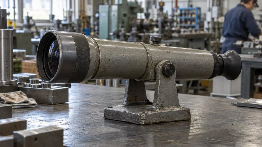
A furnace inspection record from a Japanese supplier lists the instrument as hikari koonkei (光高温計, optical pyrometer) and the reading as kido ondo (輝度温度, brightness temperature): for example, "1,000 °C." Your process sheet asks for the actual temperature of the steel, and your own handheld infrared thermometer reads something different. Both instruments may be working correctly.
A brightness temperature is not the true surface temperature. It is the temperature a perfect blackbody would need to look equally bright at the instrument's wavelength. For a surface with emissivity below 1, it reads lower than the true temperature when reflected radiation can be ignored.
This guide explains how a disappearing-filament optical pyrometer works, how it differs from infrared and two-color (ratio) thermometers, and where emissivity, viewing windows, smoke, and reflections push the reading off. A checklist and an email template for the Japanese side are near the end.
Contents
- What Is an Optical Pyrometer?
- How a Disappearing-Filament Pyrometer Works
- Brightness Temperature vs. True Temperature
- Advantages and Limits of Optical Pyrometers
- Calibration and Traceability
- When Readings Disagree: Isolating the Cause
- Checklist and Questions for the Japanese Side
- Limits of This Guide
- FAQ
- Sources
What Is an Optical Pyrometer?
An optical pyrometer finds the temperature of a hot object from the thermal radiation it gives off, without touching it. It is one kind of radiation thermometer (hosha ondokei, 放射温度計). The classic visual design is the disappearing-filament type (senjo shoshitsu-gata, 線条消失形), which uses the operator's eye as the comparison detector.
The operator overlays the image of the target on a lamp filament inside the instrument and adjusts the lamp current until the two look equally bright in a narrow red band. The instrument then converts that current to temperature. The filament is simply the thin wire in the lamp that glows when current flows through it.
Other radiation thermometers, such as infrared instruments with electronic detectors, also use radiation from the target. What differs is the wavelength band they measure, how they detect it, and how the reading is produced.
Where It Is Used: Hot, Glowing Targets
A visual optical pyrometer needs a target hot enough to glow brightly in visible light. Typical targets are molten metal, material inside a furnace, and heated wire or bar: anywhere you have a clear line of sight to the target.
As one example, CHINO Corporation's IR-URN, a disappearing-filament pyrometer with a digital display, measures at 0.65 µm and covers 700–3,500 °C (1,292–6,332 °F) across three switchable ranges. Those figures belong to that model and are not the range of every optical pyrometer.
The instrument can read such high temperatures because it only receives light from the target; the instrument itself does not have to reach that temperature. It still has its own ambient operating range, and a high measuring range does not mean it can sit in front of a furnace opening soaking up radiant heat.
Battery-powered portable models let you move between measuring points on the shop floor. If you use one that way, choose positions where you can repeat the same distance and viewing direction, so that today's reading can be compared with the last one.
With steel, quality depends on hold time and cooling as well as on heating temperature. When you manage heat treatment such as hardening and tempering, keep a single surface reading separate from the check of the full process conditions.
Optical vs. Infrared vs. Two-Color Pyrometers
A typical radiation thermometer with an electronic detector, such as a handheld infrared thermometer, processes the detector signal and displays a temperature. With a visual disappearing-filament pyrometer, a person aims at the target, adjusts the lamp current, and judges when the brightness matches.
A digital display does not change that. If the brightness match is still made by eye, the human judgment step remains, so treat "digital readout" and "automatic detection" as two separate features.
A two-color thermometer (nishoku ondokei, 二色温度計), also called a ratio pyrometer, uses the ratio of radiation measured in two wavelength bands. Comparing a filament with a target is not "measuring two colors," so do not treat a disappearing-filament pyrometer as a two-color instrument. Figure 1 compares the main approaches.
Non-contact does not mean one detection method. "Optical pyrometer" here means the visual disappearing-filament type.
| Method | What it receives | How it gets to a temperature | Main conditions to check |
|---|---|---|---|
| Contact thermometer | Heat conducted from the target to the sensing element | Converts thermoelectric voltage, resistance, etc. to temperature | Insertion, thermal contact, protection tube, wiring |
| Visual optical pyrometer | Visible radiation from the target | Matches brightness to the filament and reads from the calibrated current | Aiming, focus, match judgment, emissivity |
| Electronic radiation thermometer (e.g., infrared) | Radiation in the band set by its specification | Processes the detector signal and displays or outputs it | Field of view, target size, emissivity, optical path |
| Two-color (ratio) thermometer | Radiation in two wavelength bands | Calculates from the ratio of the two signals | Emissivity ratio at the two wavelengths, path transmission |
Two-color instruments still require checks on emissivity and the optical path. Using two wavelengths does not remove error for every target.
KELLER, a pyrometer maker, explains where ratio instruments help and where they do not:
- Where they help: dust, smoke, or a dirty window that weakens all wavelengths equally leaves the ratio, and therefore the reading, stable.
- The assumption: the reading equals the true temperature only when the emissivity is the same at both wavelengths. KELLER notes that this is seldom true in practice.
- Where they can do worse: if emissivity differs between the two wavelengths and fluctuates, the error can exceed that of a single-wavelength pyrometer, especially on non-ferrous metals.
How a Disappearing-Filament Pyrometer Works
To understand the working principle, separate two light sources: the light coming from the target, and the light the instrument makes itself. The pyrometer does not turn the target's temperature directly into a current. Instead, the operator adjusts the current in a comparison lamp.
The objective lens forms an image of the target in the same plane as the lamp filament. Looking through a filter and the eyepiece, the operator compares the two brightness levels in one field of view.
The red filter narrows the comparison to a small band of red wavelengths. Comparing brightness in a fixed band, rather than judging whether the overall color looks similar, is what ties the reading to temperature.
Real instruments also contain filters that cut the light level to switch ranges. Figure 2 shows only how the image and the comparison relate; check the actual filters and their positions in each instrument's optical design.
Two representative rays run from the top of the target to the filament plane. The blue dashed line shows only the eyepiece side; it is not a ray trace.
The filament itself glows and is seen together with the target image. Selecting a red band and cutting light are measurement functions of the optics; the figure does not mean the filter replaces eye protection.
Dark, Vanishing, and Bright Filament
When the filament current is low and the filament is dimmer than the target, you see a dark line across a bright background. As you raise the current, the filament brightens and the contrast with the background shrinks.
If the current is too high, the filament becomes brighter than the target and shows as a bright line. In that case, lower the current and look for the match point between the dark and bright settings.
When target and filament are equally bright, the edge of the filament becomes hard to see against the target. That is the "disappearing filament." The lamp is still on, and nothing physically disappears.
Set the eyepiece and the focus on the target so the comparison is easy to make. With a blurred image, or with the filament placed over the edge of the target, the match itself becomes unreliable. Figure 3 shows the three views.
Target brightness is held constant. The curved line in each view is the same filament.
Colors and line widths are for illustration. In the center view the lamp is still lit; the filament simply blends into the background.
Why Lamp Current Converts to Temperature
Raising the current changes the filament's temperature and radiation, but that alone does not tell you the target's temperature. The instrument needs a calibration that links the matching current to brightness temperature.
In calibration, the lab uses a standard lamp or a blackbody of known brightness temperature and finds the current at which the instrument's filament matches it. The instrument's scale or internal conversion then uses that relationship to read out temperature.
If the lamp or the optics change, the same current can look different. For maintenance, keep two checks apart: "the filament lights up" and "the reading agrees with a reference."
The lamp you compare against during measurement and the standard lamp used for calibration do different jobs. Calibration ties the temperature reading from the comparison lamp's current to a standard lamp or blackbody reference.
0.65 µm Is Not the Peak of Thermal Radiation
As an object heats up, its thermal radiation in the visible range grows until you can see it glow red. The peak of a blackbody's spectrum shifts to shorter wavelengths as temperature rises, but an object that has just started to glow is not emitting most strongly in the visible range.
Wien's displacement law gives the approximate peak of a blackbody's spectral radiance per unit wavelength. With wavelength in µm and thermodynamic temperature in K, the constant is about 2,898 µm·K.
For a blackbody at 700 °C, the peak is about 2.98 µm, well into the infrared. The pyrometer can still compare brightness in the visible range, so treat the peak wavelength and the instrument's measuring wavelength as separate things.
Likewise, 650 nm (0.65 µm) does not mean the filter moves toward the peak as temperature changes. The example model uses a red band at 0.65 µm, but the effective wavelength depends on the filter, the sensitivity of the eye, and other factors. Figure 4 places these values on one axis.
The wavelength axis is linear. The dots mark calculated peak positions, not radiation intensity.
The width of the red band is for illustration, not the actual passband of any model. The peak comparison ignores changes in spectral distribution caused by emissivity.
Brightness Temperature vs. True Temperature
Brightness temperature (kido ondo) is the temperature of a blackbody that would look exactly as bright as the target at a given wavelength. A blackbody is an ideal object that absorbs all radiation falling on it, and it serves as the reference for comparing the thermal radiation of real objects at the same temperature.
A target with an emissivity (hosharitsu, 放射率) below 1 emits less radiation than a blackbody at the same temperature. If reflections from the surroundings can be ignored, a brightness temperature read against a blackbody is lower than the true temperature.
If you apply an emissivity correction, use a value that fits the measuring wavelength and the condition of the surface. Do not fix the value by material name alone; check how oxide scale, roughness, temperature, and viewing angle change it.
Worked Example: How Much Emissivity Moves the Reading
Using Wien's approximation, brightness temperature and true temperature are related by what an IIT Madras course text calls the ideal pyrometer equation, shown below. The numbers are fictional and only show the size of the effect.
The wavelength term matters: put the same ε = 0.80 into the equation with a hypothetical 1.6 µm instrument, and the true temperature behind a 1,000 °C reading becomes about 1,042 °C. A shorter wavelength makes the reading less sensitive to an emissivity error. KELLER likewise recommends short-wavelength pyrometers for metals.
This is also one reason an infrared thermometer and an optical pyrometer can disagree on the same surface even when both are in calibration. Compare their wavelengths and emissivity settings before you suspect a fault.
Surface Reading vs. Internal Temperature
On opaque steel, an optical pyrometer receives radiation mainly from the visible surface. It cannot directly read the center of a thick piece or the temperature behind a wall.
During heating, the surface gets hot first and heat takes time to reach the core. A surface reading that has reached the set value does not mean the part is uniform all the way through.
Contact thermometers have the same issue: placed in the wrong spot, they do not read the temperature you need. For fluid temperature, thermowell insertion length and response raise the same question of where the sensor actually picks up its heat.
With materials that transmit light, such as glass, radiation from inside or behind the target can mix in. Do not assume a pyrometer reads only the surface of every material; check whether the target is opaque at the measuring wavelength.
The same applies to insulated piping: the temperature of the outer cladding is not the temperature of the fluid inside. With the link between insulation thickness, heat loss, and surface temperature in mind, check that the surface you are measuring actually corresponds to the temperature you need to control.
Reflections, Windows, Smoke, and Target Size
When radiation from a furnace wall reflects off shiny metal into the instrument, a reflected component adds to the light the target emits. In that case, you cannot simply assume that low emissivity always makes the reading low. Figure 5 separates the paths.
Separate the target's own radiation, reflections from the background, and the window and smoke in between. The two paths are offset for clarity.
Arrows only distinguish the paths; they do not show radiation amounts or reflection angles to scale. How much the window, smoke, and background affect the reading depends on their absorption, emission, and intensity.
Each item in the path needs its own check:
- Viewing window: what matters is how much light the window passes at the measuring wavelength. A window that looks clear to the eye does not mean its effect on the reading can be ignored. KELLER describes compensating a known window loss through the emissivity setting (instrument setting = target emissivity × path transmittance).
- Dirt, fogging, and deposits: as they build up, the light arriving from the target changes and the reading shifts. KELLER notes that deposits on the lens lower the reading. Record the window condition and the sighting path so you can tell this apart from a real temperature change.
- Background reflection: aim at a spot that furnace-wall radiation cannot reach, where possible.
- Small targets: the visual method's optics can help here, but check that the target area under the filament is clearly visible and that the instrument's magnification and focal length suit it.
- Electronic instruments: the target must fill the specified measuring field. Do not treat the laser aiming dot as the measuring area; check the target size against the distance-to-spot relationship in the spec.
Advantages and Limits of Optical Pyrometers
The main advantage is that you get temperature from the radiation of a hot part without putting a sensor on it. You avoid disturbing the target by contact, and you do not expose a sensor to the high temperature itself.
For contact sensors, durability depends on the sensor type, protection tube, atmosphere, and continuous-use conditions. You cannot choose by blanket limits such as "all thermocouples work to 2,000 °C" or "all RTDs work to 700 °C."
A temperature that falls within an optical pyrometer's range does not make the pyrometer the better choice over a contact sensor. Choose by the measuring point you need and how the measurement will be used.
Spot Checks vs. Continuous Monitoring
Visual comparison suits measurements where a person aims and judges the match. If you need to record fast-changing temperatures continuously and feed them into automatic control, consider an electronic instrument, or another type that provides the output you need.
For PID control, you cannot select an instrument by its maximum temperature alone. Response, update rate, output, and maintenance against a dirty optical path all have to match what the control loop needs.
A fine display resolution does not mean the true temperature is measured just as finely. The same holds for contact instruments such as quartz thermometers: do not judge measurement quality by the number of digits alone.
When comparing several thermometers, first check that they measure the same spot under the same conditions. A dual-element sensor gives two measurement channels, but it will not automatically agree with a non-contact reading taken on a different surface.
Calibration and Traceability
Calibration finds the difference between the instrument and a reference. Even a calibrated instrument can give different field readings if the measuring point, emissivity, or viewing window changes.
A few points help when you read Japanese calibration paperwork for a pyrometer:
- ITS-90: above the freezing point of silver (961.78 °C), the International Temperature Scale of 1990 defines temperature through Planck's radiation law, referenced to the freezing point of silver, gold (1,064.18 °C), or copper (1,084.62 °C). Above that point, the scale itself is realized with radiation thermometers.
- JCSS: Japan's accredited calibration scheme (Japan Calibration Service System) covers radiation thermometers. Ask whether the calibration is JCSS and whether the certificate carries the ilac-MRA mark if you need international acceptance.
- ITS-90 or thermodynamic temperature: a January 2020 notice from NITE told JCSS labs that NMIJ (Japan's national metrology institute) changed its radiation thermometer standards from 960 °C to 2,800 °C to values based on thermodynamic temperature rather than ITS-90. Labs were asked to state on the certificate which basis each value uses, so check that line.
- Calibration range: do not assume the error at the calibrated points continues beyond them. Compare the points on the certificate with your working range.
Japanese datasheets for radiation thermometers may cite JIS C 1612:2023, the Japanese standard on performance test methods for radiation thermometers. Documents you may see on the US and international side include ASTM E1256 (test methods for single-waveband radiation thermometers) and IEC TS 62492-1 (technical data that datasheets should state).
If performance figures matter to your acceptance, ask the supplier which standard and test conditions they follow.
When you send an instrument for calibration, state the temperature range and range settings you use, and check the reading error under those conditions. Record the error against the standard separately from the error sources on the shop floor.
When Readings Disagree: Isolating the Cause
If two instruments disagree, or today's reading differs from last week's, sort the cause by measuring point, optical path, and reading. Record temperature differences and condition differences separately, and match the comparison conditions before changing any setting. Figure 6 shows the four areas.
Keep temperature differences and measurement-condition differences apart. Align the comparison conditions before you change a setting.
Adjusting the emissivity just to close a gap hides the real cause. Use values that correspond to the target and the reference conditions.
Keep records that let you repeat the measurement:
- Where and how you aimed: instrument ID, reading, target position, and viewing direction, including which furnace opening you used and which part of the material you sighted.
- Settings: range, emissivity setting, and window or filter conditions.
- Changes over time: when the window was cleaned and how the target surface changed, so you can separate these from changes in operating conditions.
- Scatter: if a single visual match is hard to call, confirm the target is stable and look at the spread of repeated readings. Separate target fluctuation from variation in aiming and matching.
- Operator consistency: when operators change shifts, align how they focus and where they compare. Do not log a reading of only the brightest spot as the same point as a reading taken elsewhere.
Checklist and Questions for the Japanese Side
Use this checklist when a Japanese spec, inspection record, or furnace manual gives an optical pyrometer reading:
- Instrument type: visual disappearing-filament, single-band infrared, or two-color
- Measuring (effective) wavelength, for example 0.65 µm
- Whether the recorded value is a brightness temperature (kido ondo) or an emissivity-corrected temperature
- Emissivity setting used, and how it was chosen (surface condition, wavelength)
- Viewing window: material, condition, and whether its transmittance was corrected for
- Measuring point: which face, position, and furnace opening, and the viewing direction
- Possible reflections from furnace walls or heaters at that point
- Smoke, steam, or dust in the sighting path
- Calibration certificate: JCSS or not, calibration points vs. your working range, ilac-MRA mark if needed
- Whether certificate values are on ITS-90 or thermodynamic temperature (the 960–2,800 °C range covered by the NITE notice)
- Whether your process spec requires surface temperature, internal temperature, or furnace temperature
If items are missing, a short email usually clears them up. Adapt the template below and replace the bracketed parts.
Subject: Optical pyrometer readings for [furnace / process name] – measurement conditions
Hello [name],
Thank you for the inspection record dated [date]. It lists the temperature as a brightness temperature (輝度温度) measured with an optical pyrometer (光高温計). To compare it with our own measurements, could you confirm the following?
- The pyrometer model and its measuring wavelength.
- Whether the recorded value is a brightness temperature or has been corrected for emissivity, and if corrected, the emissivity value used.
- Whether the measurement was taken through a viewing window, and if so, whether the window transmittance was included in the setting.
- The measuring point (which face and position of the workpiece) and the viewing port used.
- The latest calibration certificate for the instrument, including the calibration points, and whether the values are based on ITS-90 or thermodynamic temperature.
- Whether the temperature requirement in the specification refers to the surface, the core, or the furnace atmosphere.
Best regards,
[Your name]
[Company]
Limits of This Guide
- Range, accuracy, wavelength, and features are model-specific. The CHINO IR-URN figures are one example, not common specs.
- The worked example uses fictional emissivity and transmittance values and ignores reflected radiation. Real emissivity depends on the material, surface condition, temperature, wavelength, and viewing angle.
- This guide does not give emissivity values for specific materials. Get them from the instrument maker or from measurements on your own parts.
- Calibration practice and certificate wording vary by lab. Whether a Japanese certificate is accepted in your quality system depends on your own and your customer's requirements.
- Nothing here is a work instruction for viewing furnaces. Eye protection and safe viewing positions follow your site's safety rules.
FAQ
Can You Tell the Temperature from the Color of the Glow Alone?
No. What you see also depends on ambient light and how your eyes have adapted, so color alone cannot replace an instrument. A disappearing-filament pyrometer compares brightness against a reference filament in a defined band and reads temperature from a calibrated relationship.
When the Filament Disappears, Is the Target a Blackbody?
No. A disappearing filament means the light reaching the instrument from the target matches the filament's brightness. It says nothing about whether the target is a blackbody; to find the true temperature, check emissivity and the optical path.
Can an Optical Pyrometer Measure a Moving Target?
It can, as long as you can keep the target in view and judge its brightness. Consider the speed, how long the target stays visible, and its size; if you need continuous measurement, choose the detection method and response time to suit.
Will a Calibrated Pyrometer Read the Same Through a Window?
Not necessarily. Calibration covers the instrument alone, while a window's transmittance and dirt change the light that reaches it. Compare the calibration conditions with the actual sighting path, then decide what correction and inspection you need.
Why Do My Infrared Thermometer and the Optical Pyrometer Disagree?
Different wavelengths, emissivity settings, and spot sizes are the usual suspects. The same emissivity error shifts a longer-wavelength reading more than a 0.65 µm reading, so compare both instruments' settings and aim them at the same spot before suspecting either one.
Sources
- Disappearing filament, brightness temperature, thermal radiation basics: NBS/NIST, Self-Study Manual on Optical Radiation Measurements, Technical Note 910-8 (1985), §8.2
- Ideal pyrometer equation, effective wavelength, vanishing-filament operation: S. P. Venkateshan, Mechanical Measurements, IIT Madras (NPTEL)
- IR-URN measuring principle and specifications: CHINO Corporation, digital optical pyrometer (Japanese)
- IR-URN optics and measuring band: CHINO Corporation, catalog CP-107-02 (Japanese)
- Brightness temperature vs. true temperature: Ushio, "Basics of halogen lamps," §8(1) (Japanese)
- Wien displacement constant: NIST, 2022 CODATA values (rounded to 2,898 µm·K in this article)
- Background reflection, path transmission, ratio pyrometers: KELLER, "Metrological errors"
- Emissivity and wavelength: KELLER, "Definition and influence of emissivity"
- ITS-90 above the silver point: BIPM/CCT, Guide to the Realization of the ITS-90: Radiation Thermometry (2018)
- JCSS radiation thermometers, thermodynamic temperature from 960 °C to 2,800 °C: NITE, notice to JCSS radiation thermometry labs, January 30, 2020 (Japanese)
- Single-waveband radiation thermometer test methods: ASTM E1256-17(2022)
- Datasheet terms for radiation thermometers: IEC TS 62492-1:2008
Original article in JapaneseThis guide is adapted from a MONOSCOPE article written for readers in Japan: 光高温計の原理とは?線条消失・放射温度計との違いと測定誤差
About the editor
 MONOSCOPE EditorFOUNDER & EDITOR
Spent about ten years at a plant equipment maker and a plant engineering company, proposing, designing, and commissioning equipment, then moved into web marketing. Now a web consultant for B2B manufacturers, helping them explain their products and technology. Licensed in Japan as an Energy Manager and a Third-Class Chief Electrical Engineer.
Has run an engineering blog since 2017 (500+ articles) and a Japanese YouTube channel with about 20,000 subscribers. Each English guide is written from the Japanese shop-floor point of view and checked against the cited standards.