Electro-Pneumatic vs. Pneumatic Positioners: How They Work
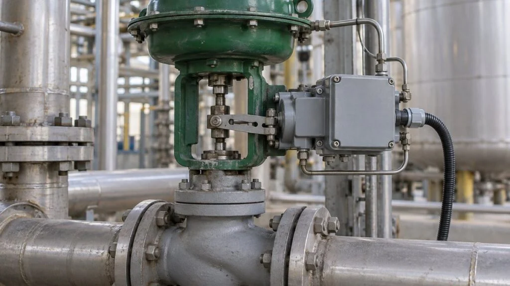
A control valve arrives on a Japanese skid. The instrument datasheet lists the accessory as "電空ポジショナー" (denku positioner), the nameplate reads something like "AVP302" or "IP8000," and the loop drawing shows a 4–20 mA signal going to it plus an instrument air line. A second valve on the same package has a "空空ポジショナー" (kuku positioner) with no wiring at all. Before you can commission, troubleshoot, or order a spare, you need to know what each device does and how to read its model code.
The short answer: a valve positioner compares the position command from the controller with the valve's actual position and adjusts the air pressure to the actuator until the two match. It does more than turn a signal into air pressure. Denku means electro-pneumatic: the command is a current signal, typically 4–20 mA. Kuku means pneumatic: the command is an air signal, typically 20–100 kPa (3–15 psi). In both cases, the power that moves the valve comes from a separate compressed-air supply.
This guide explains how positioners work, how they differ from an I/P converter, and how to read model codes from Japanese makers such as Azbil, SMC, and 3S. It ends with a checklist, questions for the Japanese supplier, and a sample inquiry email.
Contents
- Japanese Terms on Datasheets and Drawings
- What a Valve Positioner Does
- How an Electro-Pneumatic Positioner Works
- Positioner vs. I/P Converter: What Gets Fed Back
- Worked Example: 12 mA Command vs. 30% Actual Position
- Electro-Pneumatic vs. Pneumatic Positioners
- Reading Japanese Positioner Model Codes
- Selection and Installation Points
- When the Valve Does Not Follow the Command
- Checklist and Questions for the Japanese Supplier
- Limits of This Guide
- FAQ
- Sources
Japanese Terms on Datasheets and Drawings
| Japanese term | Romaji | English |
|---|---|---|
| 電空ポジショナー(電空ポジショナ) | denku positioner | Electro-pneumatic (E/P or I/P) positioner |
| 空空ポジショナー(空空ポジショナ) | kuku positioner | Pneumatic (P/P) positioner |
| 電空変換器 | denku henkanki | I/P converter (current-to-pneumatic transducer) |
| 調節計 | chosetsukei | Controller |
| 開度指令 | kaido shirei | Valve position (opening) command |
| 計装空気 | keiso kuki | Instrument air |
| 単動/複動 | tando / fukudo | Single-acting / double-acting |
| 失陥時動作 | shikkan-ji dosa | Fail action (valve behavior on loss of signal or air) |
| 防爆形 | bobaku-gata | Explosion-protected (hazardous-area) type |
Japanese spelling varies: "ポジショナー" and "ポジショナ" are the same word, and makers use both.
What a Valve Positioner Does
A pneumatic control valve moves its stem with air pressure acting on a diaphragm or piston, and the stem position sets how far the flow path is open. A diaphragm is a thin flexible membrane that moves under pressure and transfers the force of the air to the stem. The positioner fills and vents this air so that the stem travel (linear valves) or shaft angle (rotary valves) matches the value the controller asks for.
Even an electro-pneumatic positioner typically does not push the valve plug with electrical force. The small current steers compressed air, and the actuator supplies the force.
A Small Control Loop Inside the Process Loop
When the controller commands 50% open, the valve does not necessarily reach 50% right away. Packing friction and the force of the process fluid on the plug can hold it short. The positioner detects the valve position and changes the air pressure in whichever direction reduces the gap between command and position.
Mechanical positioners feed the position back through a lever and spring linked to the stem. Smart (digital) positioners use a position sensor signal instead. Azbil's technical description of its positioners states the same basic job: detect the stem position and adjust the air pressure to hold the commanded opening.
Figure 1: Position Feedback Makes the Valve Follow the Command
The controller output is the command. Instrument air is the power. Position information returns from the stem to the positioner.
Scroll sideways to see the whole figure.
Concept drawing of a single-acting diaphragm actuator. Spring direction, which side receives air, and the relationship between input and open/close direction depend on the actual specification.
This position loop watches a different quantity from the process loop. The controller measures flow, temperature, or pressure and changes the valve opening to bring that value to setpoint. The positioner then works to achieve that opening. Keeping the two roles separate makes both commissioning and troubleshooting easier.
How an Electro-Pneumatic Positioner Works
A typical analog electro-pneumatic positioner contains a torque motor: current through a coil creates a magnetic field that applies torque to a moving part. That part moves very slightly in response to the current, which changes the gap between a nozzle and a flapper. A pilot relay senses the resulting back pressure.
The nozzle is a small air outlet, and the flapper is a plate in front of it. The gap sets how easily air escapes. The pilot relay amplifies this small back-pressure change, fills or vents air, and changes the output pressure that drives the actuator.
Figure 2: A Small Gap at the Nozzle Changes How Air Escapes
Conceptual cross-section of a nozzle and flapper with the same supply-side restriction. A pilot relay follows this stage.
Scroll sideways to see the whole figure.
Whether the gap opens or closes as current rises, and how the output pressure responds when back pressure falls, depends on the mechanism. This figure alone does not tell you which way the valve moves.
SMC's instruction manual for its IP8000 series describes the balance in its design: the force produced by the input current is opposed by a spring that receives the valve movement back through a lever, and the mechanism settles where the two forces balance. The torque motor here only gives a small displacement to the moving part. It is not a rotating motor that drives the valve.
Not every positioner is built this way. Smart positioners use a sensor and a processing circuit to control position. What all of them share is the job: take a command, use supply air to move the actuator, and correct the output based on actual position.
Positioner vs. I/P Converter: What Gets Fed Back
An I/P converter (denku henkanki) turns a current signal into a matching air pressure signal. Its job ends at the output pressure. 3S's TE100 converter, for example, takes 4–20 mA and outputs 20–100 kPa. Nothing in that path looks at where the valve stem actually is.
A positioner also watches the actual position, so it changes its output pressure as much as needed to hold the same opening. A 12 mA input does not mean the output pressure will sit mid-range. Check the input command and the air pressure to the actuator as two separate values.
Figure 3: Making a Pressure Signal Is Not the Same as Matching Valve Position
Both drive the same kind of pneumatic actuator. Look for the path that returns position information.
Scroll sideways to see the whole figure.
Actuators are simplified for comparison. Some installations combine an I/P converter with a pneumatic positioner to get position control.
For more on the signal itself, see 4–20 mA vs. 1–5 V in Japanese instrumentation. A command reaching the device, air pressure coming out, and the valve sitting at the right position are three separate checks. One of them looking normal does not prove the whole loop is healthy.
Worked Example: 12 mA Command vs. 30% Actual Position
For illustration, assume 4–20 mA is mapped linearly to 0–100% valve opening, with opening increasing as current increases. Under that assumption, 12 mA is a 50% command. Reverse action, split ranging, or a non-linear characteristic setting changes the mapping, so a real valve may differ.
If the actual position is 30%, it is 20 percentage points short of the 50% command, and the positioner acts to close that gap. If the full stroke is 40 mm (about 1.6 in) and is mapped to 0–100% from the same reference point, the commanded position is 20 mm, the actual position is 12 mm, and the position error is 8 mm.
Figure 4: Work Out the Command From the Current, Then Compare It With Actual Position
Measuring the input signal alone does not confirm where the valve actually is.
input is 12 mACommand 50%
reading is 30%Gap: 20 points
20 mm − 12 mmPosition error 8 mm
Results for this hypothetical example only. Comparing command and actual position assumes the valve settings and mechanical reference points agree.
A valve at 50% open is not necessarily passing 50% of maximum flow. Flow depends on the valve's inherent flow characteristic and the differential pressure across it. Treat "the position loop is right" and "the flow is on target" as separate questions, and check the valve's characteristic (equal percentage or linear) as well.
Electro-Pneumatic vs. Pneumatic Positioners
The basic difference between denku and kuku is the command signal entering the positioner: current or air pressure. Some electro-pneumatic products take 4–20 mA and some pneumatic products take 20–100 kPa, but read either value separately from the supply air pressure that powers the actuator.
3S lists its XP pneumatic positioner with a standard input of 20–100 kPa and a supply air pressure of 0.14–0.70 MPa (about 20–100 psi) as separate specification items. A low signal pressure does not mean the supply air should be low too. Set supply pressure to meet the requirements of both the positioner and the actuator.
Figure 5: Choose the Input Signal Separately From Power and Functions
"Smart" describes internal control and diagnostics. It is not a third signal type alongside electro-pneumatic and pneumatic.
Scroll sideways to see the whole table.
| Item to check | Electro-pneumatic (denku) | Pneumatic (kuku) |
|---|---|---|
| Example input signal | 4–20 mA | 20–100 kPa (3–15 psi) |
| Power to move the valve | Compressed supply air | Compressed supply air |
| Position detection | Lever, position sensor, etc.; check the model | Mechanical detection such as a lever; check the model |
| Installation environment | Certification of the electrical parts, wiring, temperature range | Operating environment, including attached devices |
| Common selection items | Linear or rotary, single- or double-acting, stroke, supply air, fail action, mounting | |
Input ranges are typical product examples, not specifications shared by every model. Communication and diagnostic functions on smart positioners also vary by model.
Reading Japanese Positioner Model Codes
Japanese makers each use their own code structure, so there is no single rule. The examples below come from the makers' own catalogs and product pages. Use them to know what to look for, and confirm the full code with the maker's current specification sheet before ordering a spare.
Azbil AVP Smart Valve Positioners
Azbil (formerly Yamatake) sells its smart valve positioners as the AVP series. According to Azbil's catalog for the 200 series, models AVP300/301 are the integral type, and AVP200/201/202 are the remote type with a separate travel detector mounted on the valve. Within the 200 series, AVP201 adds a 4–20 mA valve travel transmitter and AVP202 adds HART communication. Azbil's product page for the 200 series lists a 4–20 mA DC input (split range available), a 140–700 kPa air supply, and a stroke range of 14.3–100 mm.
Treat the last digit as a variant code, not a universal rule. Confirm the meaning for the series on your nameplate with Azbil's specification sheet, along with suffix codes for explosion protection and mounting.
SMC IP8000 and IP8100
In SMC's web catalog, the IP8000 series is the lever type (for linear-motion valves) and the IP8100 series is the rotary type. IP8001 and IP8101 are listed as smart positioners. Explosion-proof and water-resistant versions carry additional prefixes and suffixes, so the base number alone does not tell you the hazardous-area rating.
3S XP (Pneumatic) and TE (I/P Converter)
3S Co., Ltd., a Japanese positioner maker, publishes its product code tables in English. They show how much information a Japanese code can carry.
| Field | XP pneumatic positioner (XP1__-__/____) | TE I/P converter (TE___-__/____) |
|---|---|---|
| Series | XP1 = XP100 pneumatic/pneumatic positioner | TE + 1 = TE100 (with junction box), 2 = TE200 (without) |
| Housing | 0 = standard (non-explosion-proof) | 0 = standard; 5 = flameproof Ex d IIB T6 (TE100 only) |
| Connections | 1 = single-acting, Rc 1/4; 2 = double-acting, Rc 1/4; 3 = single-acting, 1/4 NPT; 4 = double-acting, 1/4 NPT | 1 = Rc 1/4 air, G 1/2 electrical; 3 = 1/4 NPT air, G 1/2 electrical; 5 = 1/4 NPT air, 1/2 NPT electrical |
| Ambient temperature | S = −20 to 83°C; L = −50 to 60°C; H = 0 to 100°C | S = −20 to 80°C (flameproof: −20 to 60°C) |
| Mounting and cam (XP); A/M function (TE) | e.g., S1/C1a = linear, side lever, 4-phase cam (linear and equal percentage) | M = auto/manual switching function |
| Pressure gauge units | M = MPa, K = kPa, P = psi, B = bar | M2 = 0.2 MPa, K2 = 200 kPa, P2 = 30 psi, B2 = 2 bar |
| Other | Pilot relay type and orifice diameter (e.g., F1) | Gauge quantity (G0/G1/G2), regulator connection (R1/N1) |
| Input signal | B1 = 20–100 kPa; B2 = 20–60 kPa; B3 = 60–100 kPa | M1 = 4–20 mA; M2 = 4–12 mA; M3 = 12–20 mA |
Three details in these tables catch overseas buyers:
- Rc vs. NPT threads. The standard air connection is Rc 1/4 (Japanese/ISO tapered pipe thread), with 1/4 NPT as an option. Specify NPT if your site fittings are NPT.
- G 1/2 electrical entry. The TE standard electrical connection is G 1/2. A 1/2 NPT option exists, so check it against your conduit or cable gland system.
- psi gauges. 3S notes that, under Japan's Measurement Act, psi gauges cannot be sold for use in Japan. Equipment built for the Japanese market is likely to have MPa or kPa gauges. Ask for psi or bar gauges when you order for export.
Split-range input codes (B2/B3, M2/M3) make the device respond over only part of the signal range, as used when one controller output drives two valves. When a replacement comes with a different input code, the valve will not respond over the expected range.
Older Japanese plants may also have Yokogawa's YVP110 fieldbus valve positioner. Yokogawa now lists it as a discontinued product, so ask the supplier for the recommended replacement and whether the mounting and settings carry over.
Selection and Installation Points
Hazardous Areas: Signal Type Alone Does Not Decide Suitability
If an electro-pneumatic positioner will sit in a flammable atmosphere, confirm an explosion-protection rating that fits the location and the gases involved. Models in the same series can differ in construction, certification, ambient temperature range, and cable entry requirements. A label saying "explosion-proof" (bobaku-gata) is not enough to finish the selection. Japan also uses its own certification marks; see Ex d vs. Ex e and Japanese explosion-proof marks.
A pneumatic positioner takes no current input, but that does not mean it can go into any hazardous area without conditions. 3S's official specification for the XP lists the standard housing as non-explosion-proof. Confirm with the maker that the product, including any limit switches or position transmitters attached to it, suits your site.
Mounting the positioner away from the valve changes how position is fed back, how it is detected, and how the air piping responds. Choose a product designed for remote mounting, check the detector connection and piping conditions in the maker's documents, and then decide the mounting location.
Single- vs. Double-Acting and Fail Action
A single-acting actuator works against a return force such as a spring. A double-acting actuator moves by pressurizing one of two chambers. The positioner output must match the actuator. If the output ports or settings do not match, the valve will not follow the command.
Loss of the input current and loss of supply air leave different amounts of energy available to move the valve. Do not assume that a pneumatic valve always closes, or that a valve stops in place when the current is cut. Confirm the fail action with the actuator design and any accessory circuits included.
Keep the direct- or reverse-action setting separate from the safe-side position the plant requires, even when similar words describe them. See direct vs. reverse acting control valves (NO/NC, FO/FC/FL), and check both what happens when the signal rises and what happens when energy is lost.
Instrument Air Quality and Air Flow
Positioners have narrow internal air passages, so water, oil, and particles in the supply air cause malfunctions. SMC's instruction manual specifies clean, dehumidified, and filtered air, and 3S's specifications call for dry air (dew point below −30°C) with a filter finer than 5 µm just upstream of the supply port. Setting the right pressure without checking air quality is not enough.
Even with enough supply pressure, the valve may not respond as fast as needed if there is not enough air flow to move a large actuator quickly. Review tubing size and length, the pilot relay's flow capacity, and, if needed, a booster suited to the product. Check pressure and flow as two separate numbers.
Some models bleed a small amount of air from the nozzle continuously as part of normal operation. A hissing sound alone does not prove an abnormal leak. Compare against the specification and against the device's normal condition.
When the Valve Does Not Follow the Command
Record the input signal, actual position, supply pressure, and output pressure at the same time. That shows where the chain stops responding. Before blaming the positioner, check the air source, tubing, feedback linkage mounting, and friction or sticking in the valve itself. If the plant raises a valve deviation alarm, see reading a jutai (valve travel) alarm.
Replacing an analog positioner with a smart one does not guarantee that it will work with the same settings once mounted. An Azbil technical report explains the need to check the minimum operating current of the processing circuit and to confirm that input, actual position, and scale agree. Review the existing signal range and calibration conditions as part of the change.
Adjustment and disassembly are not trial-and-error jobs to do next to a valve in service. They follow the plant's safety procedures and the maker's instructions. A positioner cannot make up for a damaged valve plug or insufficient actuating force, so do not try to fix a mechanical problem with control settings alone.
SMC's instruction manual says to shut off the supply pressure and release residual pressure in the actuator and piping before removing the unit or replacing parts. It also prohibits removing the terminal cover while powered in a hazardous area. Confirm the pre-work safety conditions for both pressure and electricity with the people responsible for the plant.
Checklist and Questions for the Japanese Supplier
Positioner Checklist
- Signal type: electro-pneumatic (current) or pneumatic (air), and the exact input range, including any split range
- Full model code from the nameplate, not just the series name
- Integral or remote-mounted, linear or rotary, and the stroke or rotation angle
- Single- or double-acting output, matched to the actuator
- Fail action on loss of signal and on loss of air, checked separately
- Direct or reverse action and how it relates to the plant's safe position
- Supply air pressure range, air quality, and available air flow
- Air connection threads (Rc or NPT) and electrical entry (G 1/2 or 1/2 NPT)
- Gauge units (MPa, kPa, psi, bar)
- Hazardous-area certification that is valid where the valve will be installed, including attached switches and transmitters
- Smart functions: HART or other communication, travel transmitter, diagnostics
Questions to Ask the Japanese Side
- Is this positioner electro-pneumatic (denku) or pneumatic (kuku), and what is the input range?
- Please send the specification sheet that explains every field of the model code on the nameplate.
- What is the valve position on loss of signal and on loss of supply air?
- Was the positioner calibrated with the valve at the factory? Please send the calibration record and the settings.
- Which hazardous-area certification does the unit carry, and is it accepted under our local scheme?
- Can the air connections be supplied in NPT and the gauges in psi or bar?
- If this model is discontinued, what is the recommended replacement, and do the mounting kit and settings carry over?
Sample Inquiry Email
Subject: Positioner details for control valve [tag number]
Hello [name],
We are preparing to commission control valve [tag number] supplied with [package name]. The nameplate on the positioner reads [model code]. Could you please confirm the following?
1. Input signal type and range (including split range, if any)
2. Valve position on loss of signal and on loss of supply air
3. Factory calibration record and current settings
4. Hazardous-area certification and the certificate number
5. Required supply air pressure and air quality
We would also like a specification sheet that explains each part of the model code.
Best regards,
[Your name]
Limits of This Guide
- The input ranges, supply pressures, and model codes above are product examples from specific makers' published documents. They are not common to every model, and makers revise their code tables.
- The worked example uses an assumed linear 4–20 mA mapping and an assumed 40 mm stroke. Real valves may use reverse action, split range, or characterized settings.
- Fail action, explosion protection, and maintenance safety depend on the actual equipment and the site's rules. This guide shows what to check, not a work procedure.
- Valves driven by electric actuators are outside the scope of this guide.
FAQ
Does Every Pneumatic Control Valve Need a Positioner?
No. Whether to use one depends on the required position accuracy and response, the actuator, and the control method. On-off valves and valves that throttle continuously have different needs, so decide the required behavior and equipment arrangement first, then select.
Can an Electro-Pneumatic Positioner Run on Electricity Alone?
No. An electro-pneumatic positioner for a pneumatic actuator needs a compressed air supply in addition to the current command. Moving a valve with an electric actuator is a different method.
Does 12 mA Mean Half Flow?
Not necessarily. With a standard linear mapping, 12 mA gives a 50% position command, but flow depends on the valve characteristic, its Cv, and the differential pressure. Treat valve sizing and position control as separate questions.
Does a Smart Positioner Eliminate Position Error?
No. Even with sensors and diagnostics, a wrong mounting reference or wrong settings can make the measured position differ from the valve's real state. Azbil's report also describes matching scale, input, and detected position. Having the function does not by itself guarantee correct operation.
If Output Air Pressure Rises, Does the Valve Open?
It depends on the actuator and valve construction, the tubing, and the positioner settings. Do not assume rising pressure means opening. Match the product's action diagram against the position indicator, and check behavior both when the input rises and when air is lost.
Sources
- Operating principle, explosion-proof precautions, maintenance and supply air: SMC, IP8*00 electro-pneumatic positioner instruction manual (Japanese): principle pp. 6–7, explosion protection p. 14, maintenance and supply air pp. 18–20. Conditions apply to the models covered.
- IP8000 (lever) / IP8100 (rotary) / IP8001 and IP8101 (smart) lineup: SMC web catalog, IP8000/8100 series
- Role of position feedback in opening control: Azbil, "Valve positioner with diagnostic functions" (Japanese)
- Input current, detected position, and actual position: Azbil Technical Review, valve diagnostics accuracy and cloud services (Japanese), sections 2.1–2.2
- AVP200/201/202 remote type and AVP300/301 integral type: Azbil, Smart Valve Positioner 200 Series catalog (CA2-AVP200F)
- AVP200 series input, air supply, and stroke: Azbil, Smart Valve Positioners (AVP20_) product page
- XP product code, input signal, supply pressure, housing: 3S, Pneumatic/Pneumatic Positioner XP
- TE product code and I/P converter specifications: 3S, I/P Converter TE100
- YVP110 discontinued status: Yokogawa, Model YVP110 Advanced Valve Positioner
Original article in JapaneseThis guide is adapted from a MONOSCOPE article written for readers in Japan: ポジショナーとは?原理と電空・空空の違い、弁位置のフィードバック制御
About the editor
 MONOSCOPE EditorFOUNDER & EDITOR
Spent about ten years at a plant equipment maker and a plant engineering company, proposing, designing, and commissioning equipment, then moved into web marketing. Now a web consultant for B2B manufacturers, helping them explain their products and technology. Licensed in Japan as an Energy Manager and a Third-Class Chief Electrical Engineer.
Has run an engineering blog since 2017 (500+ articles) and a Japanese YouTube channel with about 20,000 subscribers. Each English guide is written from the Japanese shop-floor point of view and checked against the cited standards.