Feedwater Heaters: LP vs HP, Extraction Steam, TTD and DCA
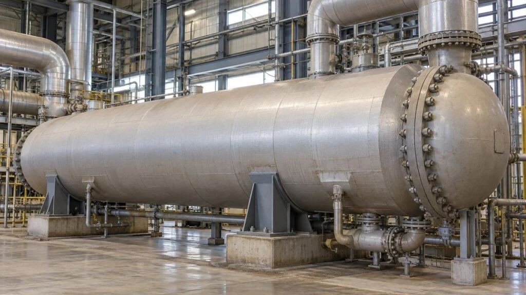
You run a cogeneration unit or a plant boiler built in Japan. The heat balance diagram labels its heaters 低圧給水加熱器 and 高圧給水加熱器, the steam lines say 第1抽気 and 第2抽気, and the operation manual talks about ドレン and 脱気器. Meanwhile the outlet temperature of one heater has been creeping down, and you want to know whether the tubes are fouled or something else is going on.
This guide maps those Japanese terms to standard English, explains the difference between LP and HP feedwater heaters, and walks through the extraction steam flow calculation. It then covers the two numbers used to judge heater health, TTD (terminal temperature difference) and DCA (drain cooler approach), and what a change in each can point to.
The guide ends with a troubleshooting checklist, questions to send to the Japanese supplier, and a sample inquiry email. One idea runs through all of it: keep the efficiency of the whole regenerative cycle separate from the heat balance of a single heater.
Contents
- Quick Reference: Japanese Feedwater Heater Terms in English
- What Is a Feedwater Heater?
- LP vs. HP Feedwater Heaters: Where They Sit
- Why Extraction Steam Improves Cycle Efficiency
- Extraction Steam Flow Calculation
- TTD and DCA: How to Read Heater Performance
- Drain Cascade and Level Control
- Costs, Pressure Drop, and Space
- Specifying or Replacing a Heater: Line Up the Conditions
- Standards You May See: HEI and ASME
- Checklist: When TTD or DCA Drifts
- Questions for the Japanese Supplier
- Limits of This Guide
- FAQ
- Sources
Quick Reference: Japanese Feedwater Heater Terms in English
The table below lists terms found on Japanese heat balance diagrams, P&IDs, and manuals, with romaji readings so you can ask about a term by name.
Table 1: Japanese Terms and Their English Equivalents
Usage can vary by manufacturer and plant. When your documents seem to use a term differently, confirm the meaning with the supplier.
| Japanese | Romaji | English |
|---|---|---|
| 給水加熱器 | kyusui kanetsuki | Feedwater heater (FWH) |
| 低圧給水加熱器 / 高圧給水加熱器 | teiatsu / koatsu kyusui kanetsuki | LP feedwater heater / HP feedwater heater |
| 抽気(第1抽気、第2抽気…) | chuki (dai-ichi chuki…) | Extraction steam, also called bleed steam (No. 1 extraction, No. 2 extraction…). Check on the diagram which number is the highest pressure. |
| 脱気器 | dakkiki | Deaerator (an open, direct-contact heater) |
| 復水器 / 復水ポンプ | fukusuiki / fukusui pump | Condenser / condensate pump |
| 給水ポンプ | kyusui pump | Boiler feed pump (BFP) |
| ドレン | doren | Heater drains (steam condensed on the shell side) |
| 過熱低減部 / 凝縮部 / ドレン冷却部 | kanetsu teigen-bu / gyoshuku-bu / doren reikyaku-bu | Desuperheating zone / condensing zone / drain cooling zone |
| 胴側 / 管側 | do-gawa / kan-gawa | Shell side / tube side |
| 水室 / 管板 / U字管 | suishitsu / kanban / U-ji-kan | Channel (water box) / tubesheet / U-tubes |
| カスケード(ドレン逆流) | kasukedo (doren gyakuryu) | Drain cascade: drains sent from a higher-pressure heater to the next lower-pressure heater |
| 非常ドレン | hijo doren | Emergency drain (also called alternate drain) |
| ベント | bento | Vent (for non-condensable gases) |
| 再生サイクル / 熱収支 | saisei saikuru / netsu shushi | Regenerative cycle / heat balance |
TTD and DCA are often written in English letters in Japanese documents as well. The term 逆流 (gyakuryu) also means "backflow" in general, as in water flowing back into the extraction line, so read it in context.
What Is a Feedwater Heater?
A feedwater heater is a heat exchanger that uses steam extracted from the turbine to preheat the water returning to the boiler. It raises the feedwater temperature in stages, so the boiler needs less heat from fuel. A cycle that returns internal heat to the feedwater this way is called a regenerative cycle.
Water leaving the condenser must be pressurized and heated before it reaches the boiler. The pumps mainly raise the pressure, while the feedwater heaters raise the temperature using extraction steam. Extraction steam is taken from the turbine partway through its expansion, so it differs in both location and pressure from the exhaust steam that goes on to the condenser.
The common closed feedwater heater is a shell-and-tube design. Feedwater flows inside the tubes, while extraction steam condenses on the shell side and passes its heat through the tube walls without the two fluids mixing. The condensed steam leaves as drains and is recovered in another heater, the deaerator, or elsewhere in the system.
The deaerator also heats water, but by direct contact between steam and water. Its main job is to remove dissolved gases, so its structure and purpose differ from a closed heater. Raising the water temperature alone does not complete deaeration, because the released gases also have to be vented.
LP vs. HP Feedwater Heaters: Where They Sit
A typical feedwater train runs condenser, condensate pump, LP heaters, deaerator, boiler feed pump, HP heaters, then boiler. Real plants usually have several heater stages, each fed from a different extraction point.
LP heaters generally sit in the condensate line upstream of the deaerator. HP heaters sit downstream of the boiler feed pump and heat feedwater that is already at high pressure on its way to the boiler. In other words, "low" and "high" refer mainly to the feedwater (tube-side) pressure, not just the extraction steam pressure.
Figure 1 shows a simplified train. Blue is water; orange is extraction steam.
Figure 1: Feedwater Flows from Cold to Hot, and Each Heater Gets Its Own Extraction
Blue is water and orange is extraction steam. The drain system is shown separately in Figure 5.
Simplified schematic. The number of stages, piping layout, extraction points, and pump locations differ from plant to plant.
Within one heater, the tube-side feedwater pressure and the shell-side steam pressure are not the same. High-pressure water can be heated by lower-pressure steam because the tube wall separates the two fluids and heat moves across it by temperature difference. On drawings, follow the feedwater path first, then check the tube-side and shell-side design pressures of each heater separately.
When tracing a system on a P&ID, draw the main feedwater line from condenser to boiler as one path first. Then add the extraction, drain, and vent lines. This order makes it harder to confuse what each line does.
Do not confuse the heaters with the condenser. Both handle condensing steam, but the condenser condenses turbine exhaust, while a feedwater heater warms the returning water.
Inside a Closed Heater: Three Zones
When extraction steam touches the outside of the tubes, it gives up heat to the feedwater and condenses. The steam releases latent heat as it condenses, so you cannot calculate the heat duty from the steam's temperature change alone.
Feedwater enters an inlet channel, flows through the tubes, and returns to an outlet channel. A U-tube design can put both inlet and outlet on one tubesheet, but not every heater uses the same tube layout. Figure 2 shows a U-tube heater in concept.
Figure 2: A Closed Heater Keeps Tube-Side and Shell-Side Fluids Apart
Conceptual section of a U-tube heater. Feedwater enters at the lower inlet, turns through the U-tubes, and leaves from the upper outlet.
Tube count, pass partitions, and support plates are simplified to show the flow path. The desuperheating and drain cooling zones are omitted.
Many heaters have up to three zones. The desuperheating zone uses the superheat in the extraction steam, the condensing zone uses mainly the heat released by condensation, and the drain cooling zone recovers more heat from the drains before they leave, so less heat is carried downstream. A given heater may have all three zones or only one or two of them.
Because each zone works differently, water level and fouling show up in the outlet temperatures in different ways. The zones also matter for the upper limit of the feedwater outlet temperature. In a heater with a desuperheating zone, the outlet can be hotter than the saturation temperature at the shell pressure.
In a plain condensing zone, the driving force for heat transfer is the gap between the steam saturation temperature and the feedwater temperature. Heat transfer area and fouling come into play here.
Why Extraction Steam Improves Cycle Efficiency
The main benefit of feedwater heating is lower heat input at the boiler, which raises the thermal efficiency of the cycle. Instead of heating cold condenser water all the way up with fuel, the cycle uses extraction steam for the low-temperature part of the job. This raises the average temperature at which the boiler adds heat.
Extraction has a cost, though: steam taken out of the turbine no longer does work in the later stages. Fuel savings do not mean power output also rises, so compare efficiency on both heat input and net work.
Thermal efficiency is net work divided by the heat the cycle receives. Starting from a basic Rankine cycle and adding the extraction split and pump work makes the effect of regeneration clear. It also shows why more extraction is not always better: the extraction pressures, the number of stages, and the temperature rise per stage have to be planned together with the turbine and boiler.
Higher feedwater temperature also changes conditions in the boiler's heat transfer surfaces. Maintaining the design feedwater conditions is important, but evaluate the benefit of smaller temperature changes separately from the gain in cycle efficiency.
Preheating the water entering the deaerator in an LP heater reduces the heating steam the deaerator needs. Drains are also recovered so the cycle reuses both water and heat. Changes in extraction flow at each stage still have to be judged on the overall heat balance.
Feedwater Heater vs. Economizer
Both heat the water going into the boiler, but the heat source differs. A feedwater heater mainly uses turbine extraction steam, while an economizer uses heat from the boiler flue gas.
So when you add a feedwater heater, evaluate it together with the flue gas side. Hotter feedwater reaching the economizer changes how much heat the economizer can recover, so track where the heat goes across the whole plant.
Some preheaters with similar names heat water with outside steam or waste heat rather than turbine extraction. In that case, state the heat source and the evaluation boundary clearly, and keep it separate from a regenerative-cycle discussion.
Extraction Steam Flow Calculation
For a single heater, match the heat the feedwater gains with the heat the extraction steam gives up on its way to becoming drains. Expressing each stream's heat as specific enthalpy (from pressure and temperature) lets you include condensation in the calculation.
Here is a fictional example. Assume a feedwater flow of 10 kg/s (about 79,000 lb/h), with inlet and outlet enthalpies of 590 and 740 kJ/kg (liquid water at roughly 140°C and 175°C, the same temperatures as in Figure 4). Each kilogram of feedwater gains 150 kJ, so the heat duty is 1,500 kJ/s, or 1,500 kW.
Now assume the extraction steam enters at 2,800 kJ/kg (slightly superheated steam at about 1 MPa) and the drains leave at 610 kJ/kg (liquid at about 145°C). Each kilogram of extraction steam gives up 2,190 kJ. The required extraction flow is 1,500 divided by 2,190, as Figure 3 shows.
Figure 3: Divide the Feedwater Heat Duty by the Heat Each Kilogram of Steam Gives Up
Textbook case for one closed heater, ignoring drains cascaded in from other heaters and heat loss to the surroundings.
In this example the extraction flow is about 6.8% of the feedwater flow (about 5,400 lb/h). That is not necessarily the same as the extraction ratio relative to turbine main steam flow. Other extractions, makeup water, or drains entering the line change the reference flow.
The 1,500 kW is heat transferred to the feedwater, not added power output. Subtracting the lost turbine work and pump power belongs to the whole-cycle calculation.
For real calculations, take the enthalpy at each point from steam tables, matching the pressure, temperature, and phase. A temperature difference times specific heat is only a rough estimate.
If drains cascade in from a higher-pressure heater, add that inflow to the heat balance as an input. Assuming all the heat comes from fresh extraction steam can overstate the required extraction flow.
In a calculation sheet, start by drawing a boundary around the heater and listing every stream that crosses it. Then decide whether the simple steam-and-feedwater equation is enough, or whether cascaded drains and vents must be included.
TTD and DCA: How to Read Heater Performance
A drop in feedwater outlet temperature does not by itself mean fouled tubes. If the extraction pressure, feedwater flow, or feedwater inlet temperature changes, the outlet temperature changes even in a healthy heater. That is why heater performance is tracked with two temperature differences.
- TTD (terminal temperature difference) = saturation temperature at the shell (extraction steam) pressure − feedwater outlet temperature
- DCA (drain cooler approach) = drain outlet temperature − feedwater inlet temperature
These are the definitions used in ASME PTC 12.1 and in EPRI guidance on heat rate monitoring. Figure 4 shows where each temperature is measured, using fictional values.
Figure 4: Line Up the Measurement Points to Read TTD and DCA
Assumed values: saturation temperature 180°C (356°F), feedwater 140 → 175°C (284 → 347°F), drain outlet 145°C (293°F).
TTD = shell-side saturation temperature − feedwater outlet temperature. DCA = drain outlet temperature − feedwater inlet temperature. A 5 K difference equals 9°F. In heaters with a desuperheating zone, TTD can be negative.
Both values are 5 K in Figure 4 only to illustrate the definitions; 5 K is not a pass mark for every heater. Compare readings with the design values, the guarantee conditions, and the heater's own healthy-condition data at the same load.
EPRI notes that expected TTD and DCA values are usually taken from the heat balance diagram, and that ASME PTC 12.1 gives a more rigorous method using the manufacturer's design data.
For orientation only, an EPRI guide on heater level control uses a reference plant with a TTD of 5°F (3°C) at all loads, and says the DCA should be about 10–15°F (5–8°C) at full load. Your heater's design values come from its own heat balance and datasheet.
DCA tells you how the drain cooling zone is working, so it does not apply the same way to a heater without one. TTD also changes meaning depending on whether there is a desuperheating zone, and some designs run with a negative TTD. Match each indicator to the structure shown on the drawings.
What a Change in TTD or DCA Can Point To
Start by checking whether the heat source changed. If the outlet temperature dropped together with the extraction pressure, the shell-side saturation temperature is also lower, so the conditions for reaching the old outlet temperature have changed. If TTD grew while extraction pressure and feedwater flow stayed about the same, look at heat transfer.
Table 2 lists common patterns. Treat each as a lead to investigate, not a diagnosis: several signs together still need inspection results or water chemistry history to confirm a cause.
Table 2: Symptoms, Possible Causes, and What to Check
Compare readings at the same load and steady state. Patterns are typical, not certain.
| Symptom | Possible causes | Check first |
|---|---|---|
| Outlet temp. down, extraction pressure also down | Change on the heat source side (lower shell saturation temperature) | Extraction pressure, load, turbine conditions |
| TTD up, extraction pressure and flow steady | Tube fouling, plugged tubes, water level too high (tubes covered), non-condensable gas buildup | Level indication, vent flow, tube-side pressure drop |
| DCA up | Water level at or below the drain cooling zone entrance, letting steam into the zone; flashing in the drain cooler | Level indication and setpoint, level control valve response |
| Tube-side pressure drop up and temperature rise down | Fouling or a change in the flow path inside the tubes | Compare at the same flow; water chemistry records |
| Drain flow up and level rising quickly | Tube leak (high-pressure feedwater entering the shell); also drain valve or drain line problems | Tube-side vs. shell-side pressure, level, drain flow trends |
Level effects on TTD and DCA are based on EPRI guidance on feedwater heater level control. Also check pressure tap locations and thermometer error before blaming the heater.
Rising tube-side pressure drop does not prove fouling if the flow also rose. Compare trends within the same flow band, together with temperatures and water quality records, before deciding on cleaning or inspection.
Logging for Trend Analysis
Daily logs are easier to compare when load, feedwater flow, each temperature, shell pressure, and water level are recorded at the same time. Look at trends before and after load changes rather than a single alarm history.
Add the time, the load, and the saturation temperature calculated from shell pressure to the log sheet. A log that only has thermometer readings cannot tell a heat source problem from a heat transfer problem; adding pressure makes that possible.
Allow for instrument lag. Do not treat values taken right after a large load change as if they were steady-state readings.
Drain Cascade and Level Control
Sending drains from a higher-pressure heater to the next lower-pressure heater in turn is called a cascade. The heat in the drains is reused downstream, but the pressure difference and the drain flow have to be controlled. Some plants instead pump drains forward into the feedwater line; check which arrangement your plant uses.
When high-pressure drains enter a lower-pressure heater, part of them can flash to steam. Size and select drain piping and valves for two-phase flow that includes flash steam, not for liquid only.
If the shell level is too high, water covers tube surface that should be heated by condensing steam, and performance drops. In abnormal conditions, water can also back up through the extraction line into the turbine, so the specified alarms and protection matter. ASME TDP-1 addresses this risk, called turbine water induction, for fossil-fueled power plants.
If the level is too low, steam can enter the drain cooling zone, and the drains are not cooled as designed. The normal level is set for each heater design; there is no single height that works for every unit.
Figure 5 separates the normal drain path from the emergency path in a two-heater example.
Figure 5: Check the Normal Drain Path and the Emergency Path Separately
Example of drains recovered from the heater with higher shell pressure to the adjacent heater with lower shell pressure. The emergency destination and protective actions are set by each plant's design.
LC = level control. Opening conditions for the emergency valve, feedwater bypass, extraction isolation, and other interlocks cannot be determined from this schematic.
If a tube leaks, high-pressure feedwater enters the shell, drain flow increases, and the level can rise quickly. High level can also come from a faulty drain valve or a blocked drain path, so follow the protection the plant was designed with.
Operators typically check that the level gauge reading matches the transmitter signal, that the valves respond, and that downstream pressure conditions are normal. Do not test by moving the level to an arbitrary value during operation. Check at the times and by the methods set in the plant procedures.
The vent removes non-condensable gases, and its path should be checked separately from the drains. Gas that collects near the tubes blocks heat transfer, so do not treat vent flow as simple steam loss to be minimized.
Level problems, falling outlet temperature, and changes in pressure drop often appear together. Rather than treating each one separately, trace in time order which flow or control change came first. That narrows down where to inspect.
Costs, Pressure Drop, and Space
Adding a heater adds equipment to recover heat, plus equipment to manage extraction steam and drains. When comparing options, include pumps, valves, instruments, and maintenance space, not just the heater price.
Small plants are not automatically worse candidates, and large ones are not automatically better. Operating hours, load swings, fuel prices, and existing piping all change the balance of benefit and cost.
Higher Cost
Initial cost covers the heater, supports, foundation, insulation, extraction piping, and drain piping. Also budget for valves and instruments rated for the pressure, and for the control system that implements protection.
For a retrofit, the outage period and the tie-in work to existing equipment are costs too. Do not count only fuel savings as the annual benefit; include inspection costs, auxiliary power, and lost operating time.
Compare on a consistent basis, such as fuel for the same power output or net output for the same fuel input. Comparing operating data from different loads or ambient conditions will misjudge the heater's effect.
More stages let the cycle use extraction steam in smaller heating steps, but they also add heat transfer area, piping, and instruments. The basic test is whether the gain from one more stage justifies its added construction and maintenance cost.
Higher Feedwater Pressure Drop
Feedwater loses pressure through the heater's tubes and channels from friction and turns. The pump selection has to cover the total head required by the system, piping included.
Check pressure drop at maximum flow and across the expected operating range, not only at rated flow. Recording inlet and outlet pressure and flow while the heater is clean gives you a baseline for spotting fouling or blockage later.
A higher-pressure heater does not necessarily have a larger pressure drop. Tube diameter, tube count, flow path length, and number of passes set the flow resistance independently of the pressure rating.
Lower tube velocity reduces pressure drop but affects heat transfer performance and heater size. Weigh heat transfer and pumping costs together.
More Installation Space
Plan for inspection and disassembly space as well as the floor area of the heater itself. Items to review include the direction the channel opens, where tubes are inspected from, and, for some designs, the space needed to pull the tube bundle.
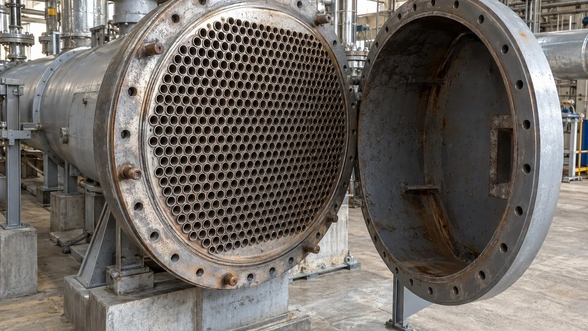
Crowding valves and piping around the heater may still allow routine checks but make major repairs difficult. Check scaffolding, lifting, and removal routes against the manufacturer's maintenance instructions and the building layout.
Horizontal and vertical heaters differ not only in footprint but in support method and overhead clearance. Drain elevation and line resistance also matter, so a heater cannot simply be dropped into any open space.
Specifying or Replacing a Heater: Line Up the Conditions
When comparing bids, give every supplier the same inlet conditions and required outlet conditions. Differences in feedwater flow and pressure, extraction steam conditions, or incoming drains change the required area, materials, and valve capacity.
A heater that meets performance at the rated point may still be unable to pass its drains at startup or low load. Give suppliers the operating range and startup/shutdown conditions, and confirm how drains will be handled when extraction pressure falls. Table 3 lists the items to align.
Table 3: Align Thermal, Pressure, and Maintenance Conditions Before Comparing Prices
Items where specifications and quotations often diverge, and the documents to check for each.
| Item | Conditions to align | Documents to check |
|---|---|---|
| Thermal performance | Feedwater flow, inlet conditions, extraction steam conditions, incoming drains | Heat balance, guarantee point, operating range |
| Pump power | Allowable feedwater-side pressure drop and maximum flow | Pressure drop calculation, system head plan |
| Pressure rating and materials | Tube-side and shell-side design conditions, water chemistry | Equipment specification, material list, inspection procedure |
| Level and drains | Normal drain destination, low-load and abnormal flow paths | System diagram, control description, protection conditions |
| Maintenance and installation | Opening direction, lifting, removal route, outage length | Layout drawing, maintenance instructions, scope of work |
Do not generalize from a single price example. Compare total cost with the same performance guarantee and the same scope of installation and maintenance.
Agree on how performance will be verified after startup before you buy. Record the pressure and temperature measurement points, flowmeter conditions, and the load band used for comparison in the commissioning records.
Comparing outlet temperatures before and after replacement is weaker evidence than comparing heat duty or temperature differences corrected to the same conditions. If instruments were replaced too, keep their effect separate from any change in heater performance.
Inspection and Repair Records
When a tube leak is suspected, match the tube-side and shell-side pressure difference with changes in level and drain flow. The leak direction can change with pressure conditions, so do not assume what you see during shutdown behaves the same way in operation.
When planning repairs, check the tube material, wall thickness, and damage location; do not limit the work to fixing the leaking tube. If damage is concentrated in one area, look for causes of recurrence such as flow-induced vibration or support condition.
Water chemistry affects tube surface condition, so link feedwater and drain analysis results to the maintenance records. Confirm that treatment conditions suit the materials, and do not change chemical treatment based only on general water quality guidelines.
Opening a heater involves hot water and residual pressure. Confirm the shutdown, isolation, draining, and cool-down conditions in the plant's work procedures. They apply to every connected system (extraction and drains as well as feedwater), not just the tube side.
Performance tests and mechanical inspections give different information, so use both. A good outlet temperature does not prove tube integrity; inspect pressure parts according to the plant's inspection plan.
Keep operating conditions, performance indicators, inspection findings, and repairs in one history. That record becomes the basis for heat transfer area and maintenance features when the heater is next replaced.
Standards You May See: HEI and ASME
Owners and engineers outside Japan often refer to the US standards below. Ask the supplier which of them, if any, the heater was designed or tested to.
- HEI Standards for Closed Feedwater Heaters (HEI 2622, 9th edition): Heat Exchange Institute standard covering heater performance, tube-side pressure loss, and mechanical and material design. Check the current edition with HEI or your standards distributor.
- ASME PTC 12.1-2015, Closed Feedwater Heaters: the performance test code for determining TTD, DCA, and tube-side and shell-side pressure losses. ASME lists the 2015 edition as R2026 (stabilized maintenance). It does not apply to heaters with partial-pass drain cooling zones.
- ASME TDP-1-2023, Prevention of Water Damage to Steam Turbines Used for Electric Power Generation: Fossil-Fueled Plants: covers protection against water induction, including heater isolation systems.
Which pressure vessel code applies to the heater shell and channel, and whether it is the Japanese code or ASME, depends on the project and the country of installation. Confirm this with the supplier and your local authority rather than assuming.
Checklist: When TTD or DCA Drifts
Use this list before calling for an outage or cleaning.
- Are the readings from steady-state operation at a load comparable to the baseline?
- Did extraction pressure change? Recalculate the saturation temperature from the current shell pressure.
- Did feedwater flow or feedwater inlet temperature change?
- Do the level gauge and level transmitter agree? Is the level at its normal setpoint?
- Is the level control valve responding normally, and is its opening different from the baseline?
- Is the vent line open and flowing as designed?
- Has tube-side pressure drop risen at the same flow?
- Has drain flow increased or has the level become unstable (possible tube leak)?
- Are the thermometers and pressure taps in the same locations as when the baseline was taken, and are they calibrated?
- Does the heater have a desuperheating zone and a drain cooling zone? (This changes what TTD and DCA mean.)
- What are the design TTD and DCA on the heater datasheet or heat balance?
Questions for the Japanese Supplier
Send these questions when the documents you received do not answer them.
- Which zones does each heater have (desuperheating, condensing, drain cooling)?
- What are the design TTD and DCA for each heater at rated load and at partial loads?
- What is the normal water level setpoint, and what are the high, high-high, and low alarm levels?
- Where do the normal drains and the emergency drains go, and what opens the emergency drain valve?
- Which extraction is "No. 1" (第1抽気) on your diagrams: the highest pressure or the lowest?
- What protection prevents water from entering the turbine through the extraction line (extraction isolation, non-return valves, high-high level trip)?
- What are the allowable operating conditions if a heater is taken out of service (bypass, load limit)?
- Were the heaters designed or tested to HEI or ASME PTC 12.1, or to another standard?
- What tube material and water chemistry limits apply?
Sample Inquiry Email
Adapt the bracketed parts to your plant.
Subject: [Plant name] HP Heater No. [X]: Design TTD/DCA and level settings
Hello [Name],
Over the past [period], the feedwater outlet temperature of HP Heater No. [X] (高圧給水加熱器) has dropped by about [value] °C at [load] % load. Extraction pressure and feedwater flow are about the same as our baseline.
Our calculated TTD has risen from [value] K to [value] K, and DCA from [value] K to [value] K.
To help us find the cause, could you send the following?
- Design TTD and DCA at [load] % and 100% load
- Normal level setpoint and alarm levels, with their reference elevation
- Whether this heater has desuperheating and drain cooling zones
- Recommended checks for venting and level control before an internal inspection
Our trend data is attached. Thank you for your help.
Best regards,
[Name]
[Company]
Limits of This Guide
- All numbers in the examples (flows, enthalpies, temperatures) are fictional and only illustrate the methods.
- The diagnostic patterns in Table 2 are typical, not certain. Several causes can act at once, and confirmation needs inspection results.
- The typical TTD and DCA values quoted from EPRI are for orientation. Your heater's design values govern.
- Heater layouts, zone arrangements, drain systems, and protection logic vary by manufacturer and plant. Follow your plant's procedures and the supplier's instructions.
- Operation, isolation, and inspection decisions belong to the plant's responsible engineers under the applicable codes and local regulations.
FAQ
What Is the Difference Between LP and HP Feedwater Heaters?
They are mainly distinguished by feedwater pressure. LP heaters sit upstream of the deaerator, and HP heaters sit downstream of the boiler feed pump. Shell-side extraction pressure and tube-side feedwater pressure are separate, so check both on the specification.
Why Does Extracting Steam Improve Efficiency?
Extraction reduces work in the later turbine stages, but preheating the feedwater also reduces the heat the boiler must supply. The extraction points and number of stages are designed so that net work divided by heat input improves.
Is the Deaerator a Feedwater Heater?
Yes. In a regenerative cycle it can be treated as an open, direct-contact feedwater heater. It heats water by mixing it with steam and removes dissolved gases, so unlike a closed heater, the fluids mix.
Can Feedwater Leave the Heater Hotter Than the Extraction Steam Saturation Temperature?
Yes, in heaters with a desuperheating zone. That zone uses the superheat of the extraction steam, so the feedwater outlet can exceed the saturation temperature at the shell pressure, giving a negative TTD.
Are Smaller TTD and DCA Values Always Better?
Not as a rule. Judge them against the heater's design, its structure, and its own baseline at the same operating conditions. TTD in particular means something different depending on whether there is a desuperheating zone, and some designs have a negative TTD.
Can the Plant Keep Running With a Heater Out of Service?
That depends on the feedwater bypass, extraction isolation arrangement, and the boiler's feedwater temperature limits. Check the allowable load and protection steps for operation without the heater in the plant's operating procedures.
Sources
- TTD and DCA definitions, zones, negative TTD with desuperheating zones: EPRI, "Turbine Cycle Heat Rate Monitoring" (1012220)
- Effects of incorrect heater level on DCA and TTD, typical design values, turbine water induction: EPRI, guide on feedwater heater and drain tank level control (1003472)
- ASME PTC 12.1 scope and status: ASME, "PTC 12.1 Closed Feedwater Heaters"
- HEI 2622, 9th edition: Accuris, HEI Standards for Closed Feedwater Heaters
- ASME TDP-1-2023: ASME, TDP-1-2023 table of contents
- Regenerative Rankine cycle: University of Waterloo, regenerative Rankine cycle
- Heat rate improvement: EPRI, Heat Rate Improvement Reference Manual
- Tube leak indicators (level control valve position, drain flow): Heat Exchanger World, "Feedwater heater leak detection"
- Feedwater heater modeling: Argonne National Laboratory, feedwater heater model
- LP and HP feedwater heater products: Seo Koatsu Kogyo, LP feedwater heater (Japanese); HP feedwater heater (Japanese)
Original article in JapaneseThis guide is adapted from a MONOSCOPE article written for readers in Japan: 給水加熱器とは?低圧・高圧の違いと再生サイクル、抽気量の計算
About the editor
 MONOSCOPE EditorFOUNDER & EDITOR
Spent about ten years at a plant equipment maker and a plant engineering company, proposing, designing, and commissioning equipment, then moved into web marketing. Now a web consultant for B2B manufacturers, helping them explain their products and technology. Licensed in Japan as an Energy Manager and a Third-Class Chief Electrical Engineer.
Has run an engineering blog since 2017 (500+ articles) and a Japanese YouTube channel with about 20,000 subscribers. Each English guide is written from the Japanese shop-floor point of view and checked against the cited standards.