Should You Insulate Valves? Heat Loss, Cost and Payback
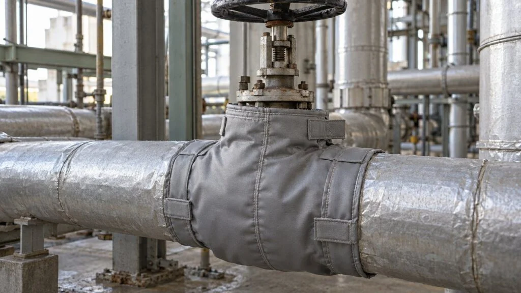
During an energy walk-down, you find a steam line that is fully insulated except for its valves. The bodies and flanges are bare, hot to the touch, and losing heat every hour the line runs. Is a removable insulation jacket worth buying for each one?
Insulating a hot valve cuts the heat lost to the surroundings and the energy the heat source must burn to replace it. How much of the valve to cover depends on the valve and cover specifications, so that the insulation does not get in the way of operation or leak checks.
The answer comes from a short valve insulation heat loss calculation. Take the difference in heat loss between the bare and insulated valve, multiply by the hours the valve is actually hot, and multiply by the price of heat. Dividing the installed cost of the jacket by that annual saving gives the simple payback.
This guide works through the full calculation for a 2-inch and a 4-inch globe valve, shown in both SI and US units (W and Btu/h). It then compares the result with published U.S. Department of Energy (DOE) figures and ends with a survey checklist and a request-for-quote template you can reuse.
Contents
- Where a Bare Valve Loses Heat
- How to Calculate Valve Heat Loss
- Worked Example: Bare 2-Inch and 4-Inch Globe Valves
- Adding 20 mm (0.8 in) of Insulation
- Defining the Heat Price: JPY/kJ vs. $/MMBtu
- How the Box Model Compares with DOE Figures
- Payback for a Removable Insulation Jacket
- Keep the Valve Inspectable
- Checklist: Valve Insulation Survey and Quote
- Where This Estimate Does Not Apply
- FAQ
- Sources
Where a Bare Valve Loses Heat
Insulating the pipe does not stop the loss if the valve body and flanges are left exposed. On a system with many valves, multiplying the loss per valve by the number of valves and the operating hours lets you rank which ones to fix first.
Heat leaves the valve surface in two ways: convection to the surrounding air and radiation to nearby surfaces. Air movement and surface condition both change the result. That is why nominal size alone does not determine the annual loss.
The figure below shows the main heat paths on an uninsulated globe valve.
Figure 1: Heat Escaping from an Exposed Valve Body
Heat leaves through the body surface, and also through the stem and the end connections.
Schematic of heat paths only. It does not show the actual flow passage or seat design.
How to Calculate Valve Heat Loss
To compare the bare and insulated valve on equal terms, this example uses one simple model for both. The fluid is at 200°C (392°F), the ambient air is at 20°C (68°F), and both stay constant. The steady-state heat loss is estimated with a flat-wall model of equal area before and after insulation.
The table lists every assumed value. All of them are illustrative inputs, not data for a specific valve.
| Input | Assumed value | What it represents |
|---|---|---|
| Inside heat transfer coefficient h₁ | 10,000 W/(m²·K) | Heat transfer from the fluid to the valve wall |
| Wall conductivity λ₁ and thickness L₁ | 84 W/(m·K), 0.010 m (0.39 in) | An assumed wall resistance for illustration |
| Insulation conductivity λ₂ | 0.05 W/(m·K) (about 0.35 Btu·in/(h·ft²·°F)) | Used in the insulated case |
| Outside effective coefficient h₂ | 20 W/(m²·K) | Convection and radiation combined into one assumed value |
| Annual hot hours H | 7,000 h/yr | Hours per year the valve runs at this temperature |
| Heat price p | JPY 0.002/kJ (JPY 2,000/GJ) | Cost per unit of heat delivered to the valve |
Real values for material, wind speed, and temperature have to be set separately for each valve. The simple model also leaves out the actual valve shape, the larger outer surface of the insulation, and heat bridges through the flanges and stem.
Step 1: Overall Heat Transfer Coefficient U
For the bare valve, the overall heat transfer coefficient U combines three resistances in series: inside film, wall conduction, and the outside surface. Add the resistances, then take the reciprocal, just as you would for a heat exchanger.
Step 2: Heat Loss Rate and Annual Cost
The heat loss rate is U times the area A times the temperature difference between fluid and air, expressed in watts. To get an annual cost, convert that rate to kJ/h and keep the rate and the yearly total in separate units.
A watt is already a rate (energy per unit time). Multiplying watts by hours gives watt-hours, not kJ, so you need the factor of 3.6 to connect the result to a price in JPY/kJ.
In US units, multiply Btu/h by hours to get Btu per year, then divide by 1,000,000 for MMBtu.
Worked Example: Bare 2-Inch and 4-Inch Globe Valves
Japanese drawings and equipment lists give valve sizes in the JIS "A" series, which is based on millimeters. In this example, 50A corresponds to NPS 2 (2-inch) and 100A to NPS 4 (4-inch). Both are nominal sizes, not actual outside dimensions.
50A (2-Inch) Globe Valve
For the calculation, the 50A valve is replaced by a box 80 mm wide, 80 mm high, and 145 mm long (3.15 × 3.15 × 5.71 in). These dimensions are only an example. Not every 50A valve has this outline.
Figure 2 shows the two simplified shapes used for the 2-inch and 4-inch cases.
Figure 2: Simplified Shapes and How the Area Is Counted
The two end faces that connect to the pipe are excluded; only the four sides count.
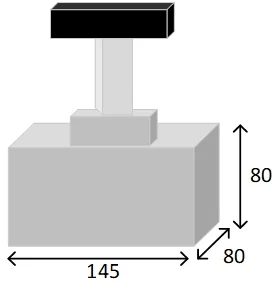 50A example: 80 × 80 × 145 mm
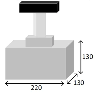 100A example: 130 × 130 × 220 mm
Simplified shapes that leave out the stem and handwheel. Dimensions in mm.
The two 80 mm square ends are pipe connections, so only the four 80 × 145 mm sides count as heat transfer area. Multiplying by 10−6 converts mm² to m², which gives 0.0464 m² (0.50 ft²).
Under these conditions, one valve loses about 166 W (567 Btu/h). Over 7,000 hours that is about 4.19 GJ (3.97 MMBtu) of heat, which costs about JPY 8,382 a year at the assumed price.
This calculation covers only heat conducted through the valve wall. Steam escaping through a leak is a separate loss and is not included.
The same equations can compare pipe lengths or insulation conditions on straight pipe. A long cylinder and an irregular valve body need different geometry treatment, so match the model to the object.
100A (4-Inch) Globe Valve
The 100A example uses a box 130 mm wide and high and 220 mm long (5.12 × 5.12 × 8.66 in), again excluding the two end faces. Because U and the temperature difference are the same, the larger area gives a proportionally larger heat loss.
What changed between the two sizes is the surface area defined for each example. Scaling by the ratio of nominal sizes would miss differences in length and shape, so set the area from the outline of the actual valve.
Valve type matters too. At the same nominal size, a ball valve, globe valve, and butterfly valve have different body and bonnet shapes, so decide how much to cover based on the valve's actual construction.
Adding 20 mm (0.8 in) of Insulation
Next, add a 20 mm layer of insulation to the same shapes under the same temperatures. The insulation adds resistance to the heat path, so less heat escapes for the same temperature difference.
With a conductivity of 0.05 W/(m·K), a 20 mm layer has a thermal resistance of 0.4 m²·K/W. That is far larger than the total resistance of the bare valve (about 0.05 m²·K/W), so U drops sharply.
Figure 3 shows the resistances in series once the insulation layer is added.
Figure 3: The Insulation Layer Adds Thermal Resistance
Local cross-section with a 20 mm insulation layer outside the valve wall.
Equal-area resistance model. A full 3D calculation including the larger cover surface and heat bridges is a separate task.
Put this U and each area into the same heat loss equation as before. Multiplying by hours and price separates the cost of the heat still lost after insulation from the saving the insulation delivers.
The table in Figure 4 puts the bare and insulated results side by side.
Figure 4: The Bare-vs.-Insulated Difference Is the Annual Saving
Same conditions for both: 7,000 hours per year and a delivered heat price of JPY 0.002/kJ.
| Example | Bare | 20 mm insulation | Annual saving |
|---|---|---|---|
| 50A (2-inch) | 166.31 W 567 Btu/h 598.72 kJ/h JPY 8,382/yr | 18.55 W 63 Btu/h 66.78 kJ/h JPY 935/yr | 147.76 W (504 Btu/h) 3.72 GJ (3.53 MMBtu)/yr About JPY 7,447/yr |
| 100A (4-inch) | 410.04 W 1,399 Btu/h 1476.16 kJ/h JPY 20,666/yr | 45.74 W 156 Btu/h 164.66 kJ/h JPY 2,305/yr | 364.31 W (1,243 Btu/h) 9.18 GJ (8.70 MMBtu)/yr About JPY 18,361/yr |
Estimates under identical model assumptions. The amounts are heat-loss costs at an assumed heat price, not product prices.
You can also get the annual saving directly from the difference in heat loss.
In this example, insulation cuts heat loss by about 89%. Both sizes show the same percentage because they share the same bare U and the same insulated U, and each keeps its area and temperature difference unchanged before and after insulation.
With everything else equal, valves with a larger temperature difference or more operating hours save more per year. In a real installation, wet insulation, gaps, and exposed flanges all reduce the effect.
Thicker insulation can be compared the same way. Thickness also changes the outer surface area, the outside heat transfer, and the material cost, so adding thickness alone does not tell you where the lowest annual cost lies.
Defining the Heat Price: JPY/kJ vs. $/MMBtu
The JPY 0.002/kJ used here is the cost of heat delivered to the valve. That is JPY 2,000 per GJ, or about JPY 2,110 per MMBtu. If you start from the purchase price of fuel instead, you must include the efficiency of the boiler or other heat source to put both on the same basis.
If pf is the fuel price per unit of heating value and η is the heat source efficiency, the delivered heat price is pf divided by η. If your delivered heat price already includes the efficiency, do not divide by it a second time.
The DOE Steam Tip Sheet #17 uses the same logic in US units. Its formula divides the saving in Btu/h times hours per year by the boiler efficiency times 106 to give fuel saved in MMBtu, then multiplies by the fuel price.
Applying the tip sheet's example assumptions (80% boiler efficiency, $8.00/MMBtu natural gas) to the box model gives the following results. The $8.00 figure comes from the 2012 tip sheet and is not a current price; use your own.
Mixing higher and lower heating values also changes how price and efficiency line up, even at the same fuel price. Use the same heating-value basis for price and boiler efficiency, and record which boundary your cost calculation uses.
How the Box Model Compares with DOE Figures
DOE publishes energy savings for removable insulated valve covers, calculated with a program that meets ASTM C680 (heat loss and surface temperature calculations). The figures assume a 1-inch pad on an ANSI 150-pound-class flanged valve, 65°F ambient air, and zero wind.
The table shows the DOE values at 400°F, the row closest to this example's 392°F, with watt equivalents added.
| Valve size (NPS) | DOE saving at 400°F, Btu/h | Same, W (converted) |
|---|---|---|
| 3-inch | 2,900 | about 850 |
| 4-inch | 3,400 | about 996 |
| 6-inch | 5,800 | about 1,700 |
| 8-inch | 8,300 | about 2,430 |
| 10-inch | 10,800 | about 3,170 |
| 12-inch | 12,500 | about 3,660 |
| 4-inch box model in this guide (392°F, 20 mm) | 1,243 | 364 |
The box model gives about 37% of the DOE figure for a 4-inch valve. The inputs differ (insulation thickness, ambient temperature, outside coefficient), but the most visible difference is area. DOE's values are for a flanged valve, while the box leaves out the flanges, stem, and handwheel.
Treat the box model as a way to learn the method and rank valves against each other. For purchase decisions, measure the real outline or use a tool built on ASTM C680, such as the free 3E Plus program from the North American Insulation Manufacturers Association (NAIMA, now the Insulation Institute).
DOE's own worked example shows the scale on a larger valve. A 1-inch pad on a bare 6-inch gate valve on a 250 psig saturated steam line (406°F) saves 5,992 Btu/h, or 65.6 MMBtu of fuel and $525 a year at 8,760 hours, 80% efficiency, and $8.00/MMBtu.
Payback for a Removable Insulation Jacket
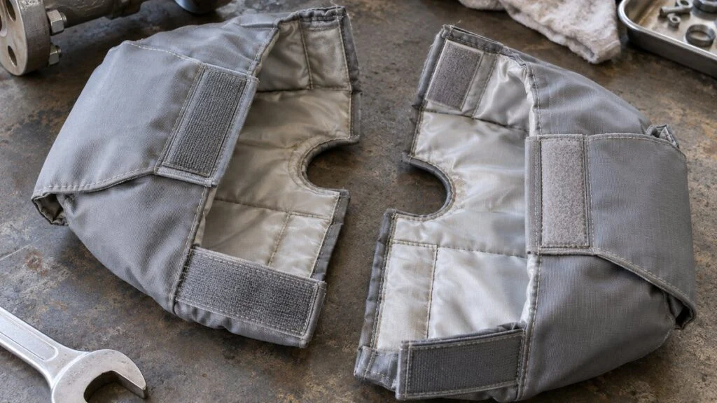
The basic rule is to divide the total installed cost for a valve by that same valve's annual saving. Use a quote that covers measuring, fitting, and any related work, not just the price of the jacket itself.
Do not combine the jacket price for one size with the heat loss calculation for another size; the payback figure then loses its meaning. In a real quote, also match the valve type, the bonnet and flange outline, and any interference with nearby equipment.
For example, assume a total installed cost of JPY 20,000 for the 50A valve and JPY 30,000 for the 100A valve. The paybacks are then about 2.69 and 1.63 years. These costs are made-up figures for the calculation, not product or market prices.
Figure 5 shows the payback point for the 50A example as the year when cumulative savings reach the installed cost.
Figure 5: When Cumulative Savings Reach the Installed Cost
50A example: installed cost JPY 20,000, saving JPY 7,447/yr, payback about 2.69 years.
Simple payback with constant operation and heat price. Maintenance, interest, and replacement costs are handled separately.
If operating hours fall from 7,000 to 3,500, the annual saving halves under the same conditions. With the same installed cost, the payback doubles, so count the actual hours the valve is hot rather than calendar hours.
At 3,500 hours, the 50A valve saves about JPY 3,724 a year and takes about 5.37 years to recover JPY 20,000. The 100A valve saves about JPY 9,181 a year and pays back in about 3.27 years. The estimate of operating hours has a large effect on the decision.
If you have a target payback, run the equation backward to find the operating hours you need. For the 50A valve at JPY 20,000 and a 3-year target, with all other conditions fixed, the required hot time is about 6,266 hours a year.
The same equation, turned around, gives the most you can spend for a given payback. With the DOE example assumptions above ($8.00/MMBtu, 80% efficiency, 7,000 h/yr), a 3-year payback allows an installed cost of about $105 for the 2-inch box model and about $260 for the 4-inch. Compare these limits with your supplier's quote, not with a list price.
Comparing the required hours with the actual operating schedule helps you sort which valves to tackle first, even on a large site. Also factor in how long the valve will stay in service before removal or replacement, and the cost of removing and refitting the jacket at each inspection.
Installed cost varies with site conditions, whether the work is new construction or a retrofit. The same jacket can cost much more in total where scaffolding or a planned shutdown is needed.
Intermittent operation adds heat stored at startup and heat lost while cooling down, which a steady-state calculation does not fully capture. Start by separating the hours the valve stays hot, then move the valves with the biggest effect to measurement or a more detailed study.
When you assess savings across a whole facility, keep energy supplied at the source separate from heat at the equipment. Using consistent heat balance boundaries prevents double-counting insulation savings and boiler efficiency improvements.
Keep the Valve Inspectable
Valves are operated and maintained, so the insulation must come off and go back on easily, not just reduce heat loss. Removable jackets make inspection easier, but a jacket left off after maintenance brings the heat loss right back for as long as it stays off.
DOE's tip sheet makes the same point: insulation on pipes, valves, and fittings is often damaged or removed during maintenance and not replaced. Figure 6 shows how to separate the covered area from the points that need access.
Figure 6: Separate the Removable Covers from the Inspection Points
Insulate the valve body while keeping access for operation and leak checks.
Concept of maintenance access. The insulated area must follow the valve, actuator, and cover manufacturers' instructions.
Plan the covers so they do not block the travel of the handwheel and stem, or the gland and flange points used for leak checks. On motorized valves and pneumatic control valves, do not cover the actuator or instruments by default; follow the area the manufacturer specifies.
For example, an Azbil instruction document for a motorized valve actuator used on chilled and hot water specifies that the connection must not be hidden by insulation. This only illustrates following a manufacturer's instruction. It is not a basis for applying that product's specifications, dimensions, or temperature range to a 200°C steam valve.
Leave the space needed for operation and for any limit switches that confirm open and closed positions on the actual model. Recording the insulated area and the inspection points on a drawing makes it easier to measure for covers and to check the refit after inspection.
Outdoors, or where washdown water reaches the valve, add torn jackets, water entry, and wet insulation to the inspection list. Corrosion under insulation is hard to see from outside, so fitting insulation does not end the maintenance task.
If you find a leak or corrosion, handle it through the site's inspection and repair procedures rather than covering it up. Removing insulation from hot equipment requires the site's safety conditions, such as shutdown, isolation, and cooling. DOE also notes that existing insulation should be checked for asbestos under OSHA regulations before removal; confirm the applicable local rules with qualified personnel.
Checklist: Valve Insulation Survey and Quote
Record each valve as one complete set of data. Do not reuse one set of dimensions for several valves; splitting valves with different outlines or installation conditions makes it easier to check the results against quotes.
| Item | What to record |
|---|---|
| Valve tag | Tag number and location on the P&ID or layout |
| Size and type | JIS "A" size and NPS (for example, 100A / NPS 4), valve type, end connection (flanged, welded, threaded) |
| Temperature | Fluid temperature in °C and °F; indoor or outdoor; typical air movement |
| Hot hours | Actual hours per year at temperature (not calendar hours); continuous or intermittent |
| Current state | Bare, partly insulated, damaged jacket, wet insulation |
| Outline | Body, bonnet, and flange dimensions; face-to-face length |
| Access | Handwheel travel, gland and leak check points, actuator, limit switches, nearby interference |
| Maintenance | Inspection frequency, planned removal or replacement date |
| Heat price | Price basis (fuel or delivered heat), heating-value basis, boiler efficiency used |
| Existing insulation | Whether it needs an asbestos check before removal (confirm with the site's safety function) |
When you request a quote, send the same data to every supplier so the paybacks are comparable. The template below can be adapted for a supplier in Japan or elsewhere.
Subject: Request for quotation – removable insulation jackets for valves We are planning removable insulation jackets for the valves listed in the attached sheet (tag, size in JIS A and NPS, valve type, end connection, fluid temperature, indoor/outdoor, and outline dimensions). Please quote the total installed cost per valve, including on-site measurement, fabrication, fitting, and any scaffolding or other work you expect. Please also state:
Best regards, |
Where This Estimate Does Not Apply
The worked example is a teaching model. Keep these limits in mind before you use its numbers:
- The box shape simplifies the real valve; the DOE comparison suggests it can understate the surface of a flanged valve. Set the area from the actual valve's dimensions.
- The outside coefficient h₂ is a single assumed value; wind, surface emissivity, and temperature change it.
- The model ignores the larger outer surface of the insulation and heat bridges through the stem and flanges.
- Steady-state results do not cover startup, cool-down, or intermittent duty.
- The heat price, installed costs, and hours are assumptions. Replace them with your own site data and quotes.
- Steam traps, actuators, and instruments follow their own manufacturers' insulation instructions.
FAQ
Does valve insulation always pay back in 2–3 years?
No. The payback depends on installed cost, operating hours, temperature, heat price, and the heat loss saved. Even at the same nominal size, installation conditions and quote scope differ, so calculate each valve by dividing its installed cost by its annual saving.
Can I use 0.0464 m² as the area for any 2-inch valve?
No. That figure comes from an assumed 80 mm square by 145 mm box, not a standard area for 50A (2-inch) valves. Check the valve type, outline, and insulated area, and include heat bridges and the change in outer surface to the accuracy you need.
Is an insulated valve safe to touch?
Not automatically. Burn protection depends on the outer surface temperature, exposed parts, and the chance of contact, judged for the equipment as a whole. DOE's tip sheet gives a general rule of insulating surfaces above 120°F (49°C) for personnel protection, but follow your site's specifications and work rules rather than the heat loss reduction alone.
If flow through the valve drops, does heat loss drop by the same ratio?
No. The heat loss equation here is based on temperature difference and thermal resistance, not flow rate.
Flow affects the internal temperature and the inside heat transfer coefficient, so evaluate it separately from flow calculations such as Cv sizing.
Can steam traps be insulated the same way?
Not always. Heat loss affects how some traps operate, so check the manufacturer's insulation instructions first. DOE's tip sheet says inverted bucket traps can take removable snap-on insulation, while thermostatic and disc traps should be insulated according to the manufacturer's specifications.
Sources
- Removable valve insulation, energy savings table, worked example, steam traps, 120°F rule, asbestos check: U.S. Department of Energy, Steam Tip Sheet #17 "Install Removable Insulation on Valves and Fittings" (2012)
- Thermal resistance and overall heat transfer coefficient: Spirax Sarco, "Heat Transfer"
- Pipe heat loss and insulation: Spirax Sarco, "Pipes and Pipe Sizing"
- Inspection, maintenance, and corrosion under insulation: National Insulation Association, "Installation"
- 3E Plus insulation thickness program: Insulation Outlook, "NAIMA's Technical Tools: 3E Plus and 3E Estimator"
- 3E Plus built on ASTM C680: Insulation Institute, "3E Plus"
- Example of a manufacturer specifying the insulated area: Azbil, motorized valve actuator AI-6586 (Japanese)
- Gland and flange inspection points: Azbil, motorized valve actuator AI-6210 (Japanese)
Original article in JapaneseThis guide is adapted from a MONOSCOPE article written for readers in Japan: バルブに保温は必要?放熱ロス・年間費用と投資回収の計算
About the editor
 MONOSCOPE EditorFOUNDER & EDITOR
Spent about ten years at a plant equipment maker and a plant engineering company, proposing, designing, and commissioning equipment, then moved into web marketing. Now a web consultant for B2B manufacturers, helping them explain their products and technology. Licensed in Japan as an Energy Manager and a Third-Class Chief Electrical Engineer.
Has run an engineering blog since 2017 (500+ articles) and a Japanese YouTube channel with about 20,000 subscribers. Each English guide is written from the Japanese shop-floor point of view and checked against the cited standards.