Current vs Voltage Input: 4-20 mA to 1-5 V with 250 Ω
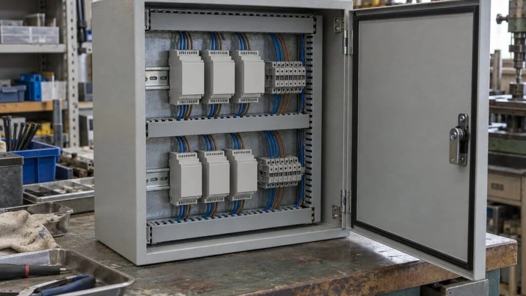
A control panel arrives from Japan. The controller and the recorder are set to "DC 1–5 V," a 250 Ω resistor sits on a terminal block, and your field transmitters all put out 4–20 mA. Now you have to decide whether to land the signal on a current input or a voltage input, and whether that resistor stays.
The short answer: a 4–20 mA signal becomes 1–5 V when it flows through a 250 Ω resistor and the receiver reads the voltage across that resistor. Current inputs hold up well over long cable runs. Voltage inputs have a high input resistance, so one signal can be shared by several devices in parallel.
Distance and the number of receivers alone do not settle the choice. This guide covers the resistor (tolerance, temperature coefficient, power), the voltage budget of a current loop, loading on voltage inputs, and a 4/12/20 mA check, followed by a checklist and questions to send to the Japanese side.
Contents
- Why Japanese Controllers and Recorders Often Use 1–5 V
- How 250 Ω Converts 4–20 mA to 1–5 V
- Choosing the Receiving Resistor: Tolerance, Temperature Coefficient, and Power
- Current Inputs: Check the Loop Voltage Budget
- Voltage Inputs: Check Loading and Ground Differences
- Current or Voltage Input? How to Decide
- Commissioning Check: 4, 12, and 20 mA
- Checklist: Before You Wire a 1–5 V or 4–20 mA Input
- Questions to Ask the Japanese Side
- Limits of This Guide
- FAQ
- Sources
Why Japanese Controllers and Recorders Often Use 1–5 V
Japanese instrument makers call 4–20 mA DC and 1–5 V DC toitsu shingo (統一信号, "unified signals"). Many Japanese process controllers, indicators, and recorders list both as standard input ranges. Yokogawa's UM33A digital indicator, for example, lists 1.000–5.000 V and 4.00–20.00 mA, with an input resistance of about 1 MΩ on the voltage range and about 250 Ω on the current range.
A common arrangement is current from the field to the panel and voltage inside the panel. A 1–5 V signal can be wired in parallel to several high-resistance inputs, such as a controller, a recorder, and a PLC.
With current, every receiver has to sit in series in the same loop.
Not every current input is 250 Ω. Mitsubishi Electric's R60AD4 PLC analog input module has 250 Ω on its current input and 1 MΩ on its voltage input. Omron's E5CC controller, by contrast, specifies 150 Ω max. for its remote SP current input.
Always read the input resistance on the datasheet of the exact model, and note which input it applies to (the main input, a remote setpoint input, and so on).
How 250 Ω Converts 4–20 mA to 1–5 V
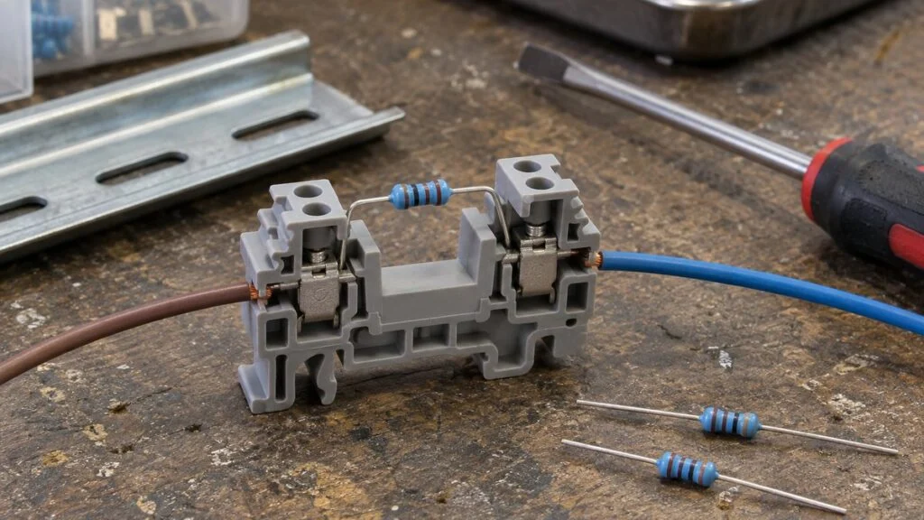
When current flows through a resistor, Ohm's law sets the voltage across it. Put 4–20 mA through 250 Ω, and you get 1 V at 4 mA and 5 V at 20 mA.
Two things matter in the wiring: where the resistor goes and where you read the voltage. The receiving resistor, called jushin teiko (受信抵抗) on Japanese drawings, goes in the current path of the loop. The voltage input's + and − terminals connect across the two ends of that resistor, in parallel with it.
Figure 1: Current Flows Through the Resistor; the Input Reads the Voltage Across It
Concept circuit with a 2-wire transmitter. If the voltage input's resistance is much higher than the receiving resistor, the input reads about 1–5 V.
Concept diagram only. It leaves out real terminal numbers, grounding, and the small parallel load of a 1 MΩ voltage input. Do not connect a loop-powering input and an external supply to the same loop. Confirm the method on the manufacturer's wiring diagram.
A device with a current input may already have a receiving resistor or current-sensing circuit inside. Adding another 250 Ω in front of it is not always needed, so check the input terminals and the range setting first.
Yokogawa's FAQ on connecting a current output to a voltage-input meter shows the same method: a 250 Ω shunt across the receiving meter's input turns 4–20 mA into 1–5 V. The same FAQ says the total resistance on that output, wiring included, should be 600 Ω or less.
Choosing the Receiving Resistor: Tolerance, Temperature Coefficient, and Power
The resistor is the conversion factor. Any error in its value goes straight into the reading, so check three things on its datasheet: resistance tolerance, temperature coefficient of resistance (TCR), and rated power.
Tolerance: Reading Error vs. Span Error
Accuracy percentages come in two kinds: percent of reading and percent of span. Keep them apart. The 1–5 V range has a span of 4 V, so a 1 mV error equals 0.025% of span.
Here is a worked example with a ±0.1% resistor (illustrative numbers, not a specific product). At 20 mA, a 0.1% resistance error shifts 5 V by 5 mV, which is 0.125% of span. At 4 mA, the same 0.1% shifts 1 V by only 1 mV, or 0.025% of span.
Temperature Coefficient: Drift Inside a Warm Panel
Even when the tolerance is fixed, the resistance moves with temperature. TCR is given in ppm/°C. Multiply it by the temperature change to get the shift in resistance.
Check the TCR of the resistor and the temperature behavior of the input across the panel's operating range. Then confirm that the total stays within the accuracy the loop needs, mounted the way it will actually be installed.
Power Rating and Fault Conditions
At 20 mA, a 250 Ω resistor dissipates 0.1 W. If the loop can carry up to 22 mA under fault conditions, that rises to 0.121 W.
Supplier guidance can call for a much higher rating. Yokogawa's FAQ on its YS series points to a 3 W, 250 Ω shunt (YS021) when a 24 V DC supply is used, and a 0.5 W precision resistor (X010-250-1) for other cases. For reference, 24 V straight across 250 Ω would dissipate about 2.3 W.
The table below shows what a few published 250 Ω products list. Use it as a guide to which fields to read, not as a recommendation.
| Product (example) | Tolerance | TCR | Rated power | Notes |
|---|---|---|---|---|
| M-System REM2-250 (plug-in receiving resistor) | ±0.1% | ±30 ppm/°C | 0.5 W at 60°C | For plug-in signal conditioners; values as shown on a third-party datasheet copy (series-level), not yet checked against M-System's own site |
| Yokogawa X010-250-1 | Not stated in the FAQ | Not stated in the FAQ | 0.5 W | Called an external precision resistor |
| DATAQ R250 | ±0.1% | Not stated on the product page | 1/2 W | Metal film |
Values come from the manufacturers' published pages and datasheet copies as of November 2026. Confirm the current datasheet before you specify a part.
The Input Resistance Also Loads the Resistor
A voltage input draws a tiny current, so strictly speaking the receiver sees 250 Ω in parallel with the input resistance. With a 1 MΩ input, the combination is about 249.938 Ω, and 20 mA gives about 4.99875 V instead of 5 V.
That is only about 0.025% low against an ideal 5 V. Whether it matters depends on the accuracy you need, so add up the resistor, input circuit, and transmitter errors, then decide the required accuracy and how to calibrate the loop.
Current Inputs: Check the Loop Voltage Budget
In a single series loop with no branches or leakage, the same current flows everywhere. As long as the transmitter can still regulate that current, more cable resistance does not change the 4–20 mA that the receiver reads.
That is why current signals tolerate long cables. The condition is that the supply covers the voltage drop in the cable plus the voltage the transmitter and receivers need.
A 2-wire transmitter takes its operating power from the signal loop, so it needs a minimum terminal voltage. Whatever is left after that minimum is what the cable and the load can use.
Figure 2: Splitting a 24 V Supply Across the Loop
Assumed example: 20 mA, 12 V transmitter minimum, 100 Ω round-trip cable, 250 Ω receiver. The remaining 5 V is the design margin to check.
In practice, check the supply's lower limit, the transmitter and input specs, and the drop across any added devices. The 20 mA numbers alone do not prove the loop works at the transmitter's maximum output current.
Written as a general condition, the minimum supply voltage must cover the transmitter minimum plus the drop across all series resistance at the maximum current:
Figure 2 needs 19 V at 20 mA, leaving 5 V from 24 V. At an assumed 22 mA, the loop needs 12 + 0.022 × 350 = 19.7 V, and the margin drops to 4.3 V. Take the maximum output current, including alarm states, from the transmitter's specification.
A supply labeled 24 V is not 24 V at the terminals under all conditions. Design with the lower limit, including variation and distribution losses. If that lower limit is 21.6 V, the margin at 22 mA shrinks to 21.6 − 19.7 = 1.9 V.
Adding a Receiver Is a Voltage Question, Not a Count
Surge protectors, isolators, and test terminals added in series also eat into the budget. When you add a receiver to an existing loop, recalculate at the output limit and in alarm states, not only at normal readings.
Add a second 250 Ω receiver to the example, and the margin at 20 mA is 0 V. At 22 mA, the loop needs 25.2 V, which a 24 V supply cannot provide.
That is why there is no fixed limit such as "three loads per loop." It depends on the input resistance of each receiver, the supply voltage, and the transmitter's allowed load.
When you put receivers in series, also check the isolation between inputs and from the power supply. If a device's common terminals are tied together inside, forcing it into a series loop can create unintended current paths. Consider a signal distributor or isolator as part of the design.
Noise and Measuring Current
Current signals resist noise comparatively well, but they are not immune. Keep signal cables away from power wiring, use proper grounding and suitable cable, and ground the shield the way the equipment manufacturer specifies.
Measuring current directly means putting the meter in series, which opens the loop and interrupts the control signal. Before changing any wiring, confirm with the site that the equipment is in a safe state and that the work permit and procedure allow it.
An ammeter also has a burden voltage from its internal sensing circuit, so it changes the loop while connected. If the loop only fails to reach full scale with the meter in place, recheck the voltage budget with the meter included.
Figure 3: Ammeter in Series, Voltmeter Across the Two Points
Simplified signal circuit including the supply and transmitter. Never connect a meter set to a current range where a voltmeter should go.
Check the meter's terminals, range, fuse, and ratings. Connecting a meter set to a current range across two points with voltage between them can cause a short circuit.
Another way is to measure the voltage across a resistor of known value and calculate I = V/R. This uses the receiving resistor already in the loop. It does not mean adding a new resistor every time, which would also add load to the loop.
A clamp meter avoids opening the loop, but it must be rated for small DC mA currents. An AC-only or high-current clamp is not necessarily usable on 4–20 mA.
Clamp only the one conductor the meter's instructions specify, never both the supply and return wires together, and check DC zeroing, resolution, accuracy, and stray magnetic fields. A fine display resolution alone does not make a clamp suitable.
Voltage Inputs: Check Loading and Ground Differences
A voltage input reads the potential difference between two points through a high input resistance. If very little current flows into the receiver, the voltage drop in the cable is also small, so voltage signals are not limited to very short runs.
To estimate the error, look at the source's output resistance, the round-trip cable resistance, and the receiver's input resistance together. A rule such as "2–3 m maximum" cannot tell you whether a voltage signal will work.
To share one voltage with several devices, you can wire their inputs in parallel. Each added input lowers the combined input resistance, so the source has to supply more current.
Figure 4: Parallel Voltage Inputs Still Add Load
Two 1 MΩ inputs combine to 500 kΩ. That forms a voltage divider with the 100 Ω total of source output resistance and round-trip cable.
Hypothetical circuit comparing DC resistance only. Check input grounding and isolation, allowable common-mode voltage, and the source's minimum allowed load separately.
Here the drop is about 0.020%, so cable length alone is no reason to expect a large loss. Swap in two devices with 10 kΩ inputs, though, and the combined resistance falls to 5 kΩ. With the same 100 Ω, the receivers see about 4.902 V, a drop of about 1.96%.
Cable capacitance, source drive capability, noise, and ground potential differences also matter. A DC voltage-divider check covers slowly changing values only, not response time or noise.
Measuring voltage means connecting across two points, so you can check the signal without interrupting it. The meter's input resistance is a load too, which matters with sources that have little drive capability.
If the two ends sit at different ground potentials, the receiver can read a different value from what was sent. In that case, consider a differential input or an isolator. Do not connect the signal's negative terminal to protective ground unless the equipment's grounding requirements call for it.
Current or Voltage Input? How to Decide
Start by drawing one wiring diagram that shows the sensor output, the receiver input, and which device supplies power. If you confuse an input card that powers the loop with one that needs an external supply, the circuit will not work even with the right resistor.
Distinguish loop-powered 2-wire transmitters from devices with separate power wiring. "Active" and "passive" mean different things to different manufacturers, so decide by asking which device supplies the voltage and which one regulates the current.
Figure 5: Move From the Signal Name to the Connection Conditions
Even with the same 4–20 mA or 1–5 V, check the combination of power, load, isolation, and input settings.
| What to check | Current input | Voltage input |
|---|---|---|
| Will the signal arrive? | Voltage margin at maximum current | Divider formed by output, cable, and input |
| Adding a receiver | Series load, isolation, shared common terminals | Combined parallel input resistance |
| Conversion resistor | Built in or not; input resistance | Read across the resistor with correct polarity |
| Measuring | In series, known resistor, or DC mA clamp | Across two points with a high-resistance meter |
| Troubleshooting | Loop power, open wire, load, range | Common wire, load, grounding, range |
Also check device-specific ratings such as maximum input voltage and voltage to ground. Do not wire real equipment from a concept diagram.
On the input card's datasheet, look beyond the current and voltage ranges. Check the input resistance, channel-to-channel isolation, and how the common terminals are arranged, for the card and for every device around it.
Once those conditions are checked, a rough guide drawn from the sections above:
- Lean toward a current input for the run from a field transmitter to the panel, where cable resistance is significant and the loop voltage budget has room.
- Lean toward a voltage input when one signal has to reach several receivers inside a panel and each has a high input resistance.
- Use an isolator or signal distributor when receivers share common terminals, sit at different ground potentials, or would push a series loop past its voltage budget.
If the receiver is a PLC, map the physical input to the program value so the range, sign, units, and limits all agree.
Commissioning Check: 4, 12, and 20 mA
In the normal 4–20 mA range, 4 mA is the bottom of the measurement range and 20 mA is the top. A 0 mA reading is distinguishable from a true zero, but it can mean an open wire, a power failure, or a device fault, so do not assume one cause.
Figure 6: Match the Electrical Values and the Display at Both Ends and the Middle
Example for a 0–100% input range with 250 Ω. Check the actual current and voltage, not only the displayed value.
Before injecting a test signal, check what it will do to control outputs and alarms, and put the equipment in the site's defined safe state. Restore the original wiring and settings afterward.
The signal can be correct while the display is wrong. If a controller is set to 0–5 V instead of 1–5 V, it scales the same voltage differently: 3 V would read 60% instead of 50%. Inject the low, middle, and high points, and confirm that the terminal readings and the display agree at each one.
Check the engineering units, not just the percentage. On a pressure transmitter ranged 0–1 MPa (0–145 psi), 12 mA means 0.5 MPa (about 73 psi).
If someone re-ranges the transmitter to 0–2 MPa, the same 12 mA now means 1 MPa. A receiver still set to 0–1 MPa will show half the real pressure while every electrical value looks normal.
The pattern of the error points to the cause:
- Off by a constant ratio across the range: suspect the scaling factor or the resistor value.
- Off only near the low end: suspect the zero point or the input range setting.
Treat transmitter output adjustment and receiver display settings as separate steps. If you adjust both at once just to make the numbers agree, you lose track of where the error was. Work from the input forward and record each result.
If the value feeds a control loop, decide how the system should handle an input fault. Before PID tuning, confirm the input range, direction, units, and what the display shows in normal and fault conditions.
For temperature signals, a thermocouple or RTD wired directly to an input is a different setup from one that goes through a converter to 4–20 mA. Make the whole chain, from sensing element to control panel, consistent, including the wiring each sensor type needs.
For predictive maintenance, also check that the accuracy and response are good enough to catch the changes you want to detect. Define what you need to measure before you choose the sensor and the transmission method.
Finally, record terminal numbers, signal ranges, resistor values, power source, shielding and grounding, and test results on the drawings. That record lets the next person confirm the assumptions when adding equipment or troubleshooting.
Checklist: Before You Wire a 1–5 V or 4–20 mA Input
Use this list when a Japanese panel, controller, or recorder meets your field instruments.
- Input type and range set on the receiver (4–20 mA, 1–5 V, or 0–5 V), and the range code on the Japanese spec sheet
- Whether the current input has a built-in resistor, and its value (250 Ω, 150 Ω max., or other)
- Location of any external receiving resistor (jushin teiko) on the terminal drawing
- Resistor tolerance, TCR, and rated power, including derating at panel temperature
- Which device powers the loop: input card, distributor, or external supply
- Loop voltage budget at maximum and alarm current, using the supply's lower limit
- Series devices in the loop: surge protectors, isolators, test terminals
- Combined input resistance of all parallel voltage receivers
- Isolation between channels and shared common terminals
- Grounding of the signal negative and the shield
- Engineering units and range on both transmitter and receiver
- Results of the 4/12/20 mA check, recorded on the drawing
Questions to Ask the Japanese Side
These questions pin down the details that drawings often leave out:
- Is this input set for 4–20 mA or 1–5 V? Can the range be changed on site, and how?
- Does the current input have a built-in resistor? What is its value?
- If an external 250 Ω resistor is used, what are its part number, tolerance, TCR, and rated power?
- Which device supplies loop power, and what is the supply's minimum voltage?
- What is the maximum allowed load resistance on this output, including wiring?
- Are the inputs isolated from each other and from the power supply?
- Is the signal negative connected to ground anywhere inside the panel?
- What engineering values do 4 mA and 20 mA correspond to, and in what units?
If you want to send these by email, a short message like this works:
Subject: Analog input details for [panel / tag numbers]
Hello [Name],
We are connecting our 4–20 mA field transmitters to your panel. For inputs [tag numbers], could you confirm the following?
- Input setting (4–20 mA or 1–5 V) and whether it can be changed on site
- Value of the built-in or external receiving resistor, with tolerance, TCR, and rated power
- Which device supplies loop power, and the maximum allowed load resistance
- Isolation between inputs, and whether the signal negative is grounded in the panel
A terminal drawing showing the resistor location would also help.
Best regards,
[Your name]
[Company]
Limits of This Guide
The numbers in this article, such as the 12 V transmitter minimum, 100 Ω cable, 22 mA fault current, 30 ppm/°C, and 21.6 V supply limit, are illustrative assumptions. They are not values for any specific device.
Input resistance, allowed load, fault current levels, isolation, and grounding vary by manufacturer and model. Wiring, live testing, and work in hazardous areas follow the site's procedures and the equipment manuals, and the responsible engineer at the site decides. This guide explains what to check, not how to do the work.
FAQ
Where Does the 250 Ω Resistor Go?
Put it in the current path of the loop, and connect the voltage input across its two ends in parallel. Some inputs already have a resistor built in, so check the wiring diagram and input setting of the actual device.
Can a Current Signal Run Over Any Cable Length?
No. The supply must cover the voltage needed by the transmitter, the round-trip cable, and the receiver load. Check noise, response, and isolation too, and do not judge by distance alone.
Are Voltage Inputs Limited to 2–3 m?
There is no universal limit. Evaluate the divider formed by output resistance, cable resistance, and input resistance, plus noise and response time, and follow the equipment manufacturer's recommendations.
Can a Clamp Meter Measure 4–20 mA?
Only one with a DC mA range and suitable resolution and accuracy. AC-only and high-current clamps may not work, so check the specifications, not just the model name.
Does a 0 mA Reading Mean a Broken Wire?
It might. Loss of power or a device fault also stops the current, so check loop power, wiring, the transmitter, and the input settings one by one. Treat it separately from the normal 4 mA low end.
Sources
- 250 Ω shunt for current output to voltage input, 600 Ω total: Yokogawa, "Can I connect transmission output (current output) to a voltage input meter?"
- X010-250-1 (0.5 W) and YS021 (3 W) shunts: Yokogawa, "Is the input shunt resistance (250 Ω) an X010 external precision resistor?"
- UM33A input ranges and input resistance: Yokogawa, UTAdvanced UM33A data sheet
- Unified signals (4–20 mA DC / 1–5 V DC): Yokogawa, JUXTA M Series for Unified Signals
- E5CC remote SP current input impedance (150 Ω max.): Omron, E5CC ratings and specifications
- R60AD4 input resistance (250 Ω current, 1 MΩ voltage): Mitsubishi Electric, MELSEC iQ-R Series selection guide
- REM2 receiving resistor specifications: M-System, REM2 data sheet (ES-9220), as reproduced on a third-party datasheet site; confirm against the manufacturer's current datasheet
- R250 shunt specifications: DATAQ Instruments, 250 Ohm Shunt Resistor
- Loop power budget, inputs, isolation: NI, "4–20 mA Current Loop Fundamentals"
- 2-wire transmitter loop power and allowed load: M-System, 2-wire transmitters (Japanese)
- Series inputs and ground loops with isolators: M-System, isolators (Japanese)
- Clamp meters, series measurement, DC vs. AC: Hioki, how to use clamp meters (Japanese)
- Short circuit when measuring voltage on a current range: Hioki, DT4255 safety information (Japanese)
- DC mA clamp example: Fluke 771 Milliamp Process Clamp Meter
- Rated power, derating, combined resistance: ROHM, "What is rated power?" (Japanese); ROHM, resistor basics (Japanese)
Original article in JapaneseThis guide is adapted from a MONOSCOPE article written for readers in Japan: 電流入力と電圧入力の違い|4–20mAを250Ωで1–5Vに変換する方法と使い分け
About the editor
 MONOSCOPE EditorFOUNDER & EDITOR
Spent about ten years at a plant equipment maker and a plant engineering company, proposing, designing, and commissioning equipment, then moved into web marketing. Now a web consultant for B2B manufacturers, helping them explain their products and technology. Licensed in Japan as an Energy Manager and a Third-Class Chief Electrical Engineer.
Has run an engineering blog since 2017 (500+ articles) and a Japanese YouTube channel with about 20,000 subscribers. Each English guide is written from the Japanese shop-floor point of view and checked against the cited standards.