Low Pump Discharge Pressure: Causes and What to Check
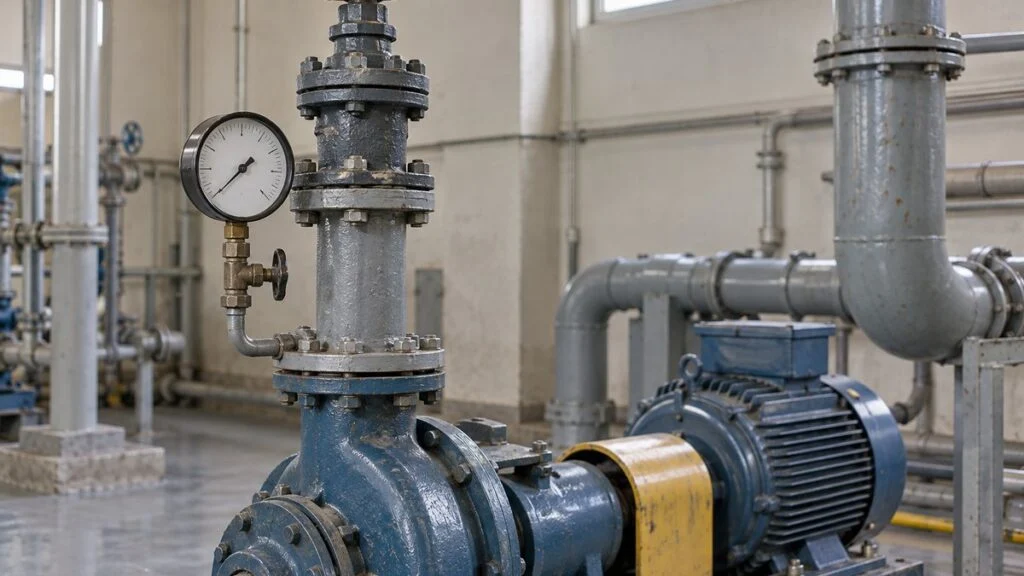
The pump is running, but the discharge gauge reads well below its usual value. Or the pressure never builds after start-up at all.
Downstream, flow at the outlets weakens and filling takes longer, liquid stops reaching upper floors, or long lines can no longer overcome their pressure losses. Users elsewhere then open their valves fully to get enough flow, which pulls pressure down even further.
The causes of low discharge pressure fall into four broad groups: not enough liquid reaching the pump, more demand than the pump can supply, a pump that is underperforming, or a restricted discharge line. The manufacturer may not be able to send someone right away. In the meantime, three readings you can take on site (motor current, pressure at several points, and the flow meter) narrow the candidates down considerably.
This guide assumes a centrifugal pump. Pumps that build pressure on a different principle, such as positive displacement pumps, show different symptoms. Treat what follows as inspection points, not work instructions; any hands-on work follows your site procedures and the pump manual.
Contents
- Check the Valves Before Anything Else
- Three Readings That Narrow Down the Cause
- Four Causes of Low Discharge Pressure
- Quick Reference: Symptom to Likely Cause
- Troubleshooting Sequence Used by Japanese Pump Makers
- What You Check and What You Hand Over
- Checklist: What to Record Before You Call
- Questions for the Japanese Supplier
- Limits of This Guide
- FAQ
- Sources
Check the Valves Before Anything Else
Before you collect readings, confirm that the discharge valve and the suction valve are both open. A valve left closed is an easy cause to overlook. It is also the first item on the troubleshooting chart that Japan's general-purpose pump manufacturers publish (covered later in this guide).
Readings only mean something when you compare them with normal values. That is why Japanese pump manuals ask operators to keep an operating log of pressure, current, flow, vibration, and noise.
Compare like with like: the same number of pumps running, the same valve openings, and the same measuring points. Gauge isolation cocks are normally kept closed except when someone takes a reading, so make sure the cock is open before you trust the number.
Three Readings That Narrow Down the Cause
Figure 1 shows what to record first. At this stage you are only collecting what has changed. The next section turns combinations of these readings into likely causes.
Record the current values, then compare them with the normal values in the operating log.
These three readings tell you what has changed. Likely causes come from how the readings combine, as shown in the next section.
Motor Current: Higher or Lower Than Usual?
Check whether the running current is higher or lower than normal. Comparing it with the rated current on the nameplate is not enough. Compare it with the usual value under the same operating conditions; that is what reveals a change.
Pressure: Where Does It Start to Drop?
Pressure varies along the line, so always record the location together with the reading. A pump can show healthy pressure at its outlet while the point of use sees low pressure.
Read three points: the suction side, the pump outlet, and the point of use. Suction pressure can fall below atmospheric, so the suction side often has a compound gauge, which reads both vacuum and positive pressure. Japanese drawings call it a rensei-kei (連成計).
On steam and hot-liquid lines, a siphon (pigtail) is often fitted ahead of the gauge. If a reading looks wrong, suspect a plugged siphon or gauge line, not just the process.
Figure 2 shows how to narrow down the cause from where pressure first drops.
The first point where pressure is low tells you which part of the system to look at.
This narrows down candidates only. Confirm with flow and current readings.
Flow Meter: Does It Match Actual Use?
Check that the flow meter reading roughly matches actual consumption. If the meter reads well above actual use, liquid may be escaping somewhere it is not being used.
Branches downstream of the meter, or a meter with limited accuracy, can also cause a mismatch. Treat a leak as a candidate to confirm, for example by inspecting the piping along the route.
Four Causes of Low Discharge Pressure
Following the liquid's path from the supply to the point of use, the causes fall into four groups:
- Not enough liquid: the supply falls short before the pump inlet (suction side)
- Too much demand: more liquid is being used than the pump can deliver
- Pump underperforming: a problem in the pump or its power supply has reduced the head it produces
- Restricted line: the piping between the pump and the point of use has narrowed
Figure 3 summarizes how the readings typically change for each group, compared with normal values.
How each reading has changed from normal tells you what to check next.
Typical tendencies, not a diagnostic table. How current changes depends on the pump type and operating point.
1. Not Enough Liquid Reaching the Pump
If the supply falls short before the pump inlet, suction pressure will be lower than usual. Less liquid enters the pump and flow drops. Entrained air also makes the liquid lighter, so motor current tends to fall.
Start with a closed suction valve or a blocked suction line. Japanese manufacturers' troubleshooting tables put these causes in the same group:
- Debris clogging the suction strainer or foot valve
- Insufficient priming (yobimizu, 呼び水), or air trapped in the pump. Japanese sources call trapped air ea-gami (エア噛み); in English it is usually called air binding or air lock.
- Air drawn in through suction pipe joints or the shaft seal
- A suction pipe inlet that is not submerged deep enough below the liquid level
A pump with trapped air cannot push liquid effectively. If water flows at first and then stops, Ebara's instruction manual points to insufficient priming or air pockets in the suction line.
Cavitation can also leave the pump running without moving liquid properly, so check for unusual noise at the pump (often described as a gravel-like rattle). Cavitation occurs when pressure at the impeller inlet falls too low, for example because the suction lift is too high or the liquid is too hot.
In NPSH terms, cavitation means the net positive suction head available (NPSHa) has fallen below the NPSH required (NPSHr) that the pump manufacturer publishes.
If you also hear noise or feel vibration, the fix depends on where the bubbles come from: liquid vaporizing (cavitation) or air leaking in.
2. Demand Exceeds What the Pump Can Supply
When consumption exceeds the pump's rated capacity, the pump cannot hold pressure. A centrifugal pump produces less head as flow increases. Higher demand therefore moves the operating point to the right on the performance curve, and discharge pressure drops.
Look for changes such as higher production rates or a damaged outdoor pipe that is leaking. Excessive leakage from worn gland packing at the shaft has the same effect. These causes show up as low pressure on the discharge side.
In this pattern, current tends to rise. The same manufacturers' tables list excessive flow as a cause of motor overload (overcurrent) and advise throttling the discharge valve back to the rated flow.
Running at excessive flow can also cause cavitation. Ebara's manual says that if vibration or noise appears and the rated pressure is not reached, the discharge gate valve should be throttled to reduce flow.
3. The Pump Itself Is Underperforming
The pump itself may be producing less head. A damaged impeller, or debris tangled in or lodged in it, reduces its ability to push liquid.
Worn wear rings have a similar effect; Japanese manuals often call them liner rings (ライナリング). As the clearance between the suction and discharge sides of the impeller grows, more liquid leaks back to the suction side without being pressurized, and pressure falls.
Ebara's manual for its S-type end-suction volute pump says to replace the liner ring once it has worn about 1 mm on the diameter. Criteria differ by model, so check the manual for your pump.
Suspect this group when suction pressure is normal and the flow meter shows nothing unusual. Three causes are easy to miss:
- Reverse rotation: often follows motor rewiring. On a three-phase motor, correcting it is electrical work for a qualified person.
- Reduced speed: low supply voltage, or a motor with a different number of poles than specified
- Frequency mismatch: a pump built for 60 Hz running on a 50 Hz supply
Reverse rotation appears in all three Japanese sources cited here (two manufacturers' manuals and the industry troubleshooting chart). Each lists it as a cause of a pump that runs but does not deliver its rated flow or head.
Head falls with the square of speed, according to the pump affinity laws. A 60 Hz pump run at 50 Hz turns at five-sixths of its design speed, so its head drops to about 70% of design. That figure assumes efficiency stays the same.
Frequency is a real trap with Japanese equipment. Eastern Japan, including Tokyo, runs at 50 Hz, while western Japan, including Nagoya and Osaka, runs at 60 Hz.
India and most of Southeast Asia use 50 Hz, while the Philippines and the US use 60 Hz. Check the rated frequency on the pump and motor nameplates against your site supply.
The opposite mismatch causes a different problem. A 50 Hz pump on a 60 Hz supply turns about 20% faster, and its power demand rises with the cube of speed, to roughly 1.7 times the design value. Confirm with the supplier before running a pump on a frequency it was not built for.
In this group, current can go either way. Debris jammed in the impeller can raise it, and the manufacturers' charts list foreign matter among the checks for motor overload. Do not diagnose from current alone; read it together with pressure and flow.
A weak power supply is rare but possible. Where power comes from an on-site generator, or where large equipment starting up causes voltage swings, check the supply voltage as well.
4. The Discharge Line Is Restricted
Debris or rust can narrow the flow path. Look for events such as foreign matter (insects, for example) getting into the line, or scale breaking loose from the pipe wall and flowing downstream.
In this case, pressure right after the pump is high, while pressure at the point of use is low. A centrifugal pump needs less shaft power as flow decreases, so current tends to fall. The industry chart is consistent with this: it advises reducing flow when a centrifugal pump is overloaded.
Sorting the causes this way shows that you mainly need the manufacturer or a repair contractor for wear or damage inside the pump. How much you hand over, though, depends on the work involved, as shown in Figure 5 later in this guide.
Quick Reference: Symptom to Likely Cause
Use this table to decide where to look first. Whatever the symptom, confirm first that the discharge and suction valves are open.
| Symptom | Likely group | Check first |
|---|---|---|
| Pressure never builds after start-up, or liquid flows at first and then stops | 1. Not enough liquid | Valves, priming, air pockets |
| Pressure drops when usage is high, and current rises | 2. Too much demand | Flow meter, production changes, leaks |
| Suction pressure is normal, but pressure is low right after the pump | 3. Pump underperforming | Rotation direction, supply voltage and frequency, impeller |
| Normal right after the pump, low only at the point of use | 4. Restricted line | Pressure difference, valves along the line, clogged piping |
| Gauge needle fluctuates | Air ingress, cavitation, or surging | See the FAQ below |
Troubleshooting Sequence Used by Japanese Pump Makers
Some cases have nothing to do with the pump: someone closed a valve and forgot to reopen it. Start with the basics and rule out causes one at a time.
The General-Purpose Pump Committee of the Japan Society of Industrial Machinery Manufacturers (JSIM) publishes a troubleshooting guide. The committee is made up of nine manufacturers, including Ebara, Kawamoto, and Teral. Its first check for a pump that runs but delivers no water, or too little, is whether the discharge valve is closed.
The chart starts with items you can check from outside: valves, priming, rotation, and air. Wear, cavitation, and a review of the design head come later. If the problem persists, the next step is to consult the manufacturer or a specialist contractor.
Figure 4 summarizes the sequence.
The order of checks when "the pump runs but delivers no water, or too little."
Summarized from the JSIM General-Purpose Pump Committee's "Troubleshooting for General-Purpose Pumps" (October 2022, Japanese), section on non-submersible pumps. If the problem persists, consult the manufacturer or a specialist contractor.
Check valves along the whole line, not just at the pump. Be especially thorough after inspections or construction work, when valves are most often left closed.
What You Check and What You Hand Over
Split the work by what it involves, not by where the cause lies. Figure 5 shows the three levels.
Decide who does what based on the work involved, not on where the cause is.
Instruction manuals also ask that disassembly and parts replacement be left to the manufacturer or a specialist contractor.
Work that opens the piping, such as cleaning a strainer, is done with the pump stopped, the valves closed, and the pressure released. De-energizing the motor and preventing an accidental start falls under your site's lockout/tagout (LOTO) procedure.
Checklist: What to Record Before You Call
Have these items ready before you contact the manufacturer or a service contractor. With them in hand, the conversation moves faster and the supplier has more to work with.
- Valves: open/closed status of the suction valve, the discharge valve, and valves along the line
- Operating conditions: number of pumps running, date and time, and anything that changed recently (production rate, maintenance, rewiring)
- Motor current: present value vs. the usual value and the nameplate rated current
- Pressure: suction (compound gauge), pump outlet, and point of use, each vs. the usual value
- Flow: flow meter reading vs. actual consumption
- Rotation: actual direction vs. the direction marked on the pump
- Power supply: nameplate frequency and voltage vs. the site supply
- Symptoms: unusual noise, vibration, gauge needle fluctuation, leaks at joints or the shaft seal
- Suction side: supply tank level and strainer condition (date of last cleaning)
Questions for the Japanese Supplier
When the pump came from Japan, some details may be available only in the Japanese documentation. These questions are worth sending early:
- Are the pump and motor built for 50 Hz or 60 Hz? What performance should we expect on our supply?
- Can you send the performance (H-Q) curve and the NPSH required for this model?
- What is the wear ring (liner ring) clearance limit for this model, and when should the rings be replaced?
- What is the correct rotation direction, and where is it marked?
- Does the pump need a minimum flow, and is a minimum flow bypass fitted?
- Is the troubleshooting table in the instruction manual available in English?
A short inquiry that carries the readings from the checklist gets a more useful first answer. Here is a sample you can adapt:
Subject: Low discharge pressure on [model / serial number]
Our [model] pump (serial no. [xxx], installed [year]) is running, but discharge pressure has dropped from about [normal value] to [current value]. Readings compared with normal: suction pressure [value / normal], pump outlet pressure [value / normal], motor current [value / normal; rated current xx A], flow [value / normal]. Rotation direction is [confirmed correct / not checked].Supply is [voltage] V, [frequency] Hz. Both suction and discharge valves are open.
Recent changes: [none / description].
Could you advise on likely causes and the next checks to make? Please also send the performance curve and the wear ring replacement criteria for this model.
Limits of This Guide
- It covers centrifugal pumps only. Positive displacement pumps behave differently.
- Changes in motor current are typical tendencies. How current responds depends on the pump type and where it operates on its curve.
- The 1 mm liner ring figure applies to one Ebara model. Use the criteria in the manual for your pump.
- The Japanese troubleshooting chart is summarized here from Japanese-language documents. Your pump's own manual takes precedence.
- Hands-on work follows your site procedures. Electrical work needs a qualified person, and disassembly belongs with the manufacturer or a specialist contractor.
FAQ
How Many psi Is 10 Meters of Pump Head?
For water, 10 m of head is about 0.1 MPa (roughly 14 psi). Head is the energy the pump gives the liquid, expressed as a height of liquid. Discharge pressure is the pressure pushing liquid out of the pump outlet.
For liquids other than water, the conversion depends on density.
How Much Can Maintenance Staff Check Themselves?
Operators can check anything visible from outside: valve positions, gauge readings, noise, vibration, and leaks. Venting air and cleaning strainers follow the site work procedure.
Correcting reverse rotation by swapping leads, and disassembling the pump to inspect impellers or liner rings, require qualifications or specialist knowledge. Instruction manuals ask that this work go to a specialist contractor or the manufacturer.
Will Throttling the Discharge Valve Raise the Pressure?
On a centrifugal pump, throttling the discharge valve raises pressure right after the pump. However, less liquid reaches the point of use, so the problem there may not be solved.
Running for long periods against a closed valve heats the liquid inside the pump and can cause failure. For that reason, systems that run at low flow sometimes have a minimum flow return line.
Why Does the Pressure Gauge Needle Fluctuate?
Air ingress and cavitation disturb the flow and can make the gauge needle swing. If pressure and flow swing widely and periodically at low flow, suspect surging as well.
The fluctuation alone cannot identify the cause. Record noise and vibration at the same time; the records help with vibration analysis and with discussions with the manufacturer.
When Should I Stop the Pump and Call for Help?
Pump manuals treat pressure, current, vibration, or noise that differs sharply from normal as a warning sign of trouble and say to act early.
If motor current exceeds the rated current, the motor can burn out. Stop the pump and consult the manufacturer or a specialist in that case, and also when unusual noise or bearing overheating continues.
Sources
- Troubleshooting order and causes (non-submersible pumps), committee members: JSIM General-Purpose Pump Committee, "Troubleshooting for General-Purpose Pumps," October 2022 (Japanese)
- Causes and fixes, liner ring replacement guideline, excessive flow and cavitation, rotation direction, operating log: Ebara, instruction manual for S-type end-suction volute pump (Japanese)
- Causes of failing to reach rated flow and head, rated current and daily checks: Terada Pump, instruction manual for TSJM2/TSJM3 volute pumps (Japanese)
- Cavitation, NPSH, and gauge fluctuation: Fluke, "Pump Cavitation: What It Is and How to Avoid It"
- Reading suction and discharge gauges: IVC Technologies, "How We Can Determine the Root Cause of Flow-Related Pump Problems with Gauges"
- Pump affinity laws: Neutrium, "Pump Affinity Laws"
- 50 Hz and 60 Hz regions of Japan: The Japan Times, "Japan's incompatible power grids" (July 19, 2011)
- Supply frequency by country: Miki Pulley, "Power Supply Situations Around the World"
Original article in JapaneseThis guide is adapted from a MONOSCOPE article written for readers in Japan: ポンプの吐出圧力が低下する・上がらない原因は?現象と調べ方・対策
About the editor
 MONOSCOPE EditorFOUNDER & EDITOR
Spent about ten years at a plant equipment maker and a plant engineering company, proposing, designing, and commissioning equipment, then moved into web marketing. Now a web consultant for B2B manufacturers, helping them explain their products and technology. Licensed in Japan as an Energy Manager and a Third-Class Chief Electrical Engineer.
Has run an engineering blog since 2017 (500+ articles) and a Japanese YouTube channel with about 20,000 subscribers. Each English guide is written from the Japanese shop-floor point of view and checked against the cited standards.