Choosing Predictive Maintenance Sensors by Failure Mode
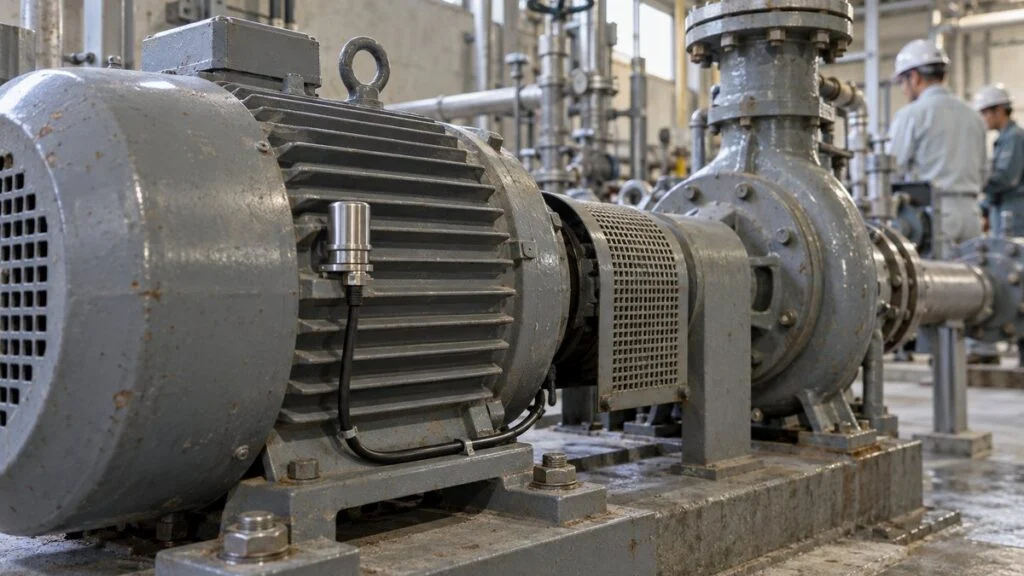
You have been asked to add condition monitoring to a line of pumps and fans, and every vendor has a different answer. One offers a wireless vibration sensor for each motor, another says motor current is enough, and a third pitches a thermal camera. All three can be right, but for different failures.
The short answer: choose predictive maintenance sensors by failure mode, not by machine type. A bearing running low on grease, a motor winding losing insulation, a loose terminal, and a compressed-air leak each change a different physical quantity first. Some failures show up first in vibration, others in current, temperature, or ultrasound.
This guide compares those four sensor types by the failures they catch, where they mount, whether the machine must stop, and what drives cost. It also shows how ISO 17359 and ISO 13374 frame the selection, and ends with a checklist and supplier questions you can reuse.
If you work with Japanese equipment or documents, two terms will come up often: yochi hozen (予知保全, predictive maintenance) and koshō mōdo (故障モード, failure mode). Several examples below come from Japanese manufacturers' published data.
Contents
- Start With the Failure Mode, Not the Machine
- How ISO 17359 and ISO 13374 Fit In
- Failure Mode vs. Detection Method: Quick-Reference Matrix
- Detection Timing on the P-F Curve
- Vibration Sensors: Bearings, Unbalance, and Misalignment
- Motor Current Sensors: Retrofit in the Panel for Electrical and Load Faults
- Temperature Sensors and Thermography: Strong on Electrical Connections, Late on Rotating Machines
- Ultrasound and Acoustic Sensors: Early Warning for Lubrication and Leaks
- How Mounting Location and Monitoring Mode Drive Cost
- Five Steps to Select Predictive Maintenance Sensors
- Checklist: What to Confirm Before You Buy
- Questions to Ask the Supplier
- Where This Guide Does Not Apply
- FAQ
- Sources
Start With the Failure Mode, Not the Machine
A common trap is to start with the machine: "What sensor goes on this pump?" The same pump can fail in several ways. Its bearings can wear, its impeller can clog with debris, or its motor winding can deteriorate.
Decide the failure mode first (what fails, and how), then pick the sensor.
Electric motors are a good example. Fuji Electric has published a breakdown of motors sent in for repair: bearing damage accounts for 50% and stator winding insulation breakdown for 30%. The remaining 20% is rotor winding insulation breakdown (6%), electrical damage at the brushes (4%), and other causes (10%).
Bearings deteriorate gradually, so their warning signs are relatively easy to catch. Stator insulation breakdown, by contrast, is often reported to occur suddenly.
Half of motors sent for repair have bearing damage; about a third have stator insulation failure.
Based on the repair breakdown in Fuji Electric's article on motor failure prediction (Japanese). The third bar combines rotor winding insulation breakdown (6%), electrical damage at the brushes, such as commutators and slip rings (4%), and other causes (10%). Shares vary with equipment and operating conditions.
Bearing failures can be traced back further. One analysis attributes about half of them to lubrication quality: unsuitable or degraded lubricant, contamination, and too much or too little grease.
So "motor bearing" is not one failure mode. A bearing whose grease is running out and a bearing with a damaged raceway produce different signals.
ISO 17359, the general guideline for machine condition monitoring, follows the same logic. It uses failure modes and symptoms from FMEA or FMECA (failure mode, effects, and criticality analysis) to decide which parameters to measure. Figure 2 applies that idea to sensor selection.
The sensor is the last thing you decide.
Adapted from the approach in ISO 17359 (Condition monitoring and diagnostics of machines — General guidelines) for the sensor-selection step.
If you are new to listing failure modes, borrow the FMEA format. It was built for design and process work, but a table of failure mode, cause, and effect works just as well for maintenance.
How ISO 17359 and ISO 13374 Fit In
Sensor vendors and plant specifications often cite ISO standards. Each covers a different layer: ISO 17359 says how to set up a monitoring program, ISO 13374 says how the data should flow, and technique-specific standards cover each measurement method.
The table lists the standards most relevant to this guide.
| Standard | What it covers | Where it helps in sensor selection |
|---|---|---|
| ISO 17359:2018 | General procedures for setting up a condition monitoring program for machines | Directs monitoring toward root-cause failure modes. Informative annexes give example parameters and match faults to measured parameters or techniques |
| ISO 13374 (Parts 1–4) | Data processing, communication, and presentation for condition monitoring and diagnostics | Part 2 defines processing blocks: data acquisition, data manipulation, state detection, health assessment, prognostic assessment, and advisory generation. Useful when you compare monitoring software or platforms |
| ISO 13379-1 | Data interpretation and diagnostics techniques: general guidelines | Turning alarms into a diagnosis |
| ISO 20816-1:2016 | Measurement and evaluation of machine vibration: general guidelines (replaced ISO 10816-1 and ISO 7919-1) | Vibration measurement conditions and evaluation. Machine-specific criteria are in other parts of the series |
| ISO 18434-1:2008 | Thermography: general procedures | Infrared thermography procedures, including emissivity and reflected temperature |
| ISO 29821:2018 | Ultrasound: general guidelines, procedures, and validation | Airborne and structure-borne ultrasound inspection |
None of these standards tells you which brand or model to buy. They give you a common structure, so when a supplier says a system is "ISO 13374 compliant," ask which blocks it actually implements.
Failure Mode vs. Detection Method: Quick-Reference Matrix
This matrix is the core of the guide. Find the failure mode you care about, then read across to see which sensor type leads.
| Failure mode | Vibration | Motor current | Temperature | Ultrasound |
|---|---|---|---|---|
| Bearing lubrication loss | Supporting | – | Late (end-stage friction heat) | Primary (earliest) |
| Bearing surface damage | Primary | Possible via spectrum analysis; less accurate than vibration | Late | Supporting |
| Unbalance, misalignment, looseness | Primary | – | – | – |
| Impeller clogging, filter clogging, heavier conveyor load | Supporting | Primary (can appear before vibration) | – | – |
| Broken rotor bars, air-gap eccentricity | – | Primary | – | – |
| Stator winding insulation decay | Barely visible | Primary (electrical side: insulation-resistance monitoring with a ZCT, not current signature analysis) | – | – |
| Loose terminals, poor contact | – | – | Primary (earliest) | – |
| Cooling fan failure, overload | – | Supporting (overload) | Primary | – |
| Compressed-air and steam leaks | – | – | – | Primary |
| Electrical discharge (corona, tracking, arcing) | – | – | – | Primary |
Figure 3 compares the same four sensor types from the other direction: mounting, downtime, and caveats.
Each type differs in what it catches, where it mounts, and how early it warns.
General tendencies only. Strengths and weaknesses change with the product specifications and the equipment.
Detection Timing on the P-F Curve
Detection timing is the column that separates the options most clearly. The P-F curve shows how a machine moves from P (the point where a potential failure begins) to F (functional failure). Placing each detection method on it makes the differences easy to see.
An article in InTech, the magazine of the International Society of Automation (ISA), gives one such order, from earliest to latest. The order is oil analysis, ultrasound, vibration, thermography, motor testing, and physical inspection.
The same article warns that late indicators such as thermography may not give enough warning to prevent damage to the shaft and bearings.
For bearing wear on rotating machines, ultrasound and vibration pick up changes before temperature does.
Based on the detection order in an ISA InTech article (2019). Motor current is left off because its position varies widely by failure mode, and the motor electrical testing listed in the source is left off with it. For some failures, such as heating at electrical connections, temperature is the earliest indicator.
This order assumes mechanical wear, such as bearing degradation on a rotating machine. For a loose terminal, temperature is the first indicator. Winding insulation decay barely shows up in vibration at all.
So do not ask which sensor is fastest. Ask which sensor is fastest for this failure mode.
Vibration Sensors: Bearings, Unbalance, and Misalignment
Vibration sensors are the most common choice for monitoring rotating machines such as motors, pumps, fans, and gear reducers. Fuji Electric recommends vibration for motor failure prediction because it is easy to monitor on site, shows abnormal trends early, and mounts directly on the housing.
Behind that recommendation is a simple fact: when a bearing deteriorates, vibration changes before temperature rises.
What Vibration Catches and Misses
Vibration readily detects mechanical faults: bearing damage, rotor unbalance, shaft misalignment, and loose bolts. These faults appear as peaks at frequencies tied to running speed or set by bearing geometry, so a frequency analysis can also point to the likely cause.
Vibration is weak at detecting electrical faults, such as winding insulation decay or poor terminal contact. It also does little for equipment that does not rotate, such as piping and electrical panels.
Acceleration vs. Velocity
Most vibration sensors are piezoelectric accelerometers, and many also output velocity by integrating the signal internally. As a rule, velocity is more sensitive to low-frequency faults such as unbalance and misalignment. Acceleration is more sensitive to high-frequency faults such as early bearing damage.
Check the sensor's frequency range here. Yokogawa's wireless Sushi Sensor (XS770A), for example, measures 3-axis acceleration and velocity plus surface temperature. Its published vibration frequency range is 10–1,000 Hz (±3 dB).
The right specification depends on whether you want to track early bearing damage at high frequencies or trend changes near running speed.
Mounting Method Changes the Usable Frequency Range
Mounting is easy to overlook. The contact between sensor and machine has its own resonance, and the weaker the attachment, the lower that resonance falls. High frequencies then cannot be measured correctly.
In a test by Toyo Corporation, the same accelerometer measured up to 12.5 kHz when stud-mounted. On a magnet for curved surfaces, the limit dropped to 3,554 Hz.
With a magnet mount, the same accelerometer reached less than 30% of its stud-mounted range.
Measured with a 603C01 accelerometer, from Toyo Corporation's article on how sensor mounting affects measurement (Japanese). The weaker the attachment, the lower the resonant frequency and the harder it is to measure high frequencies.
The same article stresses that consistent measurement conditions matter more than a perfectly flat frequency response. If the sensor, mounting method, location, and data collection stay the same, the readings work well for comparing normal and abnormal states.
If you cannot drill and tap the machine for a stud, fixing the conditions and watching the trend is a practical compromise.
Motor Current Sensors: Retrofit in the Panel for Electrical and Load Faults
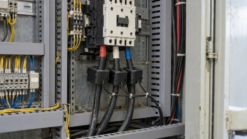
Current-based monitoring reads faults from the waveform and frequency content of the current a motor draws. The method is called motor current signature analysis (MCSA). It uses the motor itself as the sensor, so nothing has to be mounted on the machine.
What Current Catches
Current is good at catching electrical and magnetic faults inside the motor, such as broken rotor bars and air-gap eccentricity, as well as changes on the load side. A clogged pump impeller, a blocked fan filter, or a heavier conveyor load can show up in current before it shows up in vibration.
Some sources say spectrum analysis can also detect bearing wear, because bearing vibration slightly modulates the current. For bearing diagnosis, though, vibration measured directly on the machine generally performs better.
Easy Installation Where the Machine Is Hard to Reach
Current sensors mount on the power cables inside the control panel. As one manufacturer explains, clamp-on current sensors do not require cutting any wires, so they can be fitted without modifying existing wiring. Follow your site's electrical safety rules and let a qualified person do any work inside the panel.
The harder a machine is to reach (high up, in tight spaces, or in hazardous areas), the more current monitoring pays off.
Watch For: Inverter Drives and Load Changes
The weakness of current monitoring is that current varies widely with load and operating conditions. On machines with variable-speed inverter drives, or where load changes with the product being made, you need a way to separate changes caused by faults from changes caused by operating conditions.
Inverter drives need attention for both vibration and current. Fuji Electric's vibration monitoring system, for example, lists removal of inverter carrier components as a feature.
Some product lines split these functions. Omron's K6CM motor condition monitor comes in a current-diagnosis type, a vibration-and-temperature type, and an insulation-resistance type. The insulation type detects leakage current with a zero-sequence current transformer (ZCT) on the power cables, so it can monitor insulation resistance while the motor stays energized.
Stator winding insulation breakdown made up 30% of motor repairs in Figure 1 and often happens suddenly. Electrical monitoring like this suits it better than vibration does.
Temperature Sensors and Thermography: Strong on Electrical Connections, Late on Rotating Machines
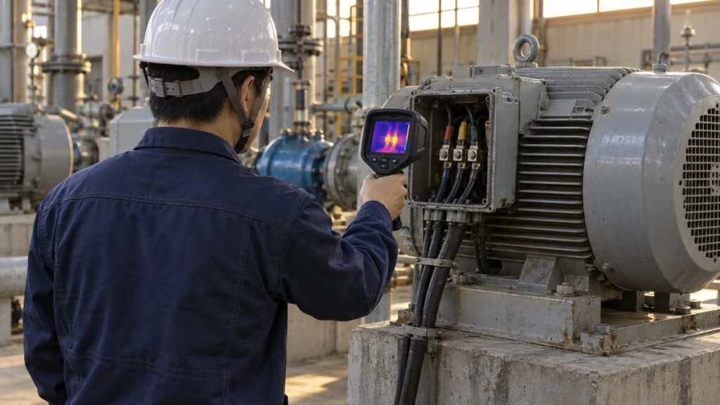
Temperature is easy to measure and easy for shop-floor staff to relate to, but it needs care on rotating machines. A glossary from Fukuda Koeki, a Japanese maintenance-instrument supplier, notes that by the time temperature rises, the machine is often already in critical condition.
The reason is that a hot bearing is often an end-stage symptom: lubrication has failed and friction heat is building.
Best Use: Heating in Electrical Equipment
Electrical equipment is where temperature becomes the earliest indicator. In switchgear and control panels, aging can loosen cables and terminals, which raises contact resistance and causes abnormal heating.
Nippon Avionics, a Japanese thermal camera maker, explains that periodic thermographic inspection finds these spots early, safely, and quickly. Typical fixes include retightening.
A thermal camera images energized equipment from a distance, so inspectors do not have to approach live parts. A common setup is to attach contact temperature sensors where continuous monitoring is needed and cover everything else with periodic thermal rounds.
Supporting Role on Rotating Machines
Temperature still has a place on rotating machines. Cooling fan failure and overheating from overload are hard to see any other way, and many vibration sensors include a built-in temperature sensor.
Think of temperature not as the main early-warning tool but as insurance against sudden changes.
Judge temperature by the rise above ambient, not by the absolute value. Equipment temperature follows outdoor temperature from summer to winter and day to night, so thresholds set on absolute values can produce more false alarms.
Ultrasound and Acoustic Sensors: Early Warning for Lubrication and Leaks
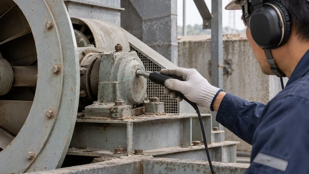
Sound-based monitoring comes in two forms. Microphones pick up the audible range, and dedicated sensors capture ultrasound above the range of human hearing. The two behave quite differently, so treat them separately.
Ultrasound: The Earliest Signal of Lubrication Problems
Ultrasound picks up the tiny friction in a bearing whose lubrication is starting to fail. On the P-F curve it sits to the left of vibration, meaning it detects change earlier. Jim Hall, executive director of The Ultrasound Institute, writes that ultrasound detects a defect before vibration and before infrared.
A common practice is acoustic lubrication: greasing a bearing while listening to its ultrasound signal. Hall's guideline is to lubricate when the reading is 8–10 dB above the previous baseline. Greasing when needed, in the amount needed, rather than on a fixed schedule, also helps avoid overgreasing, which can cause heat and blow out seals.
Ultrasound also finds compressed-air and steam leaks. Leaks barely register in vibration or current, so ultrasound is the usual tool for finding them.
Electrical discharge, including corona, tracking, and arcing, is another target. According to UE Systems, discharges produce high-frequency sound that ultrasound instruments can detect, which lets you scan enclosed gear before opening it.
Microphones With AI: Non-Contact, but Plant Noise Gets in the Way
Anomalous sound detection, which collects operating sound with microphones and uses AI to spot departures from normal, is spreading. NTT's technology learns normal sounds and flags sounds that deviate from them. Its advantage is that nothing has to be mounted on the machine.
In a plant where many machines run at once, though, background noise is loud and the target sound is hard to isolate. NTT researchers note that a system must avoid both missed detections and false alarms to earn users' trust.
Accuracy achieved in a quiet test environment may not carry over to a real production floor. Check this before you commit.
How Mounting Location and Monitoring Mode Drive Cost
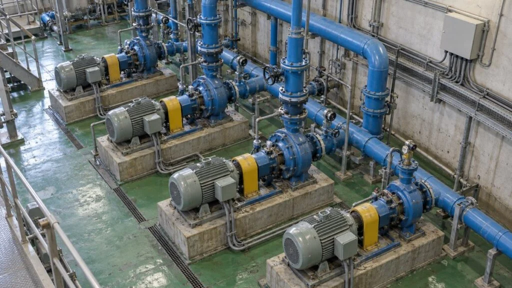
Sensor price gets the attention, but wiring, power, and the data-collection system have a bigger effect on total cost.
Murata Manufacturing divides vibration monitoring into three modes. Online monitoring measures continuously, offline monitoring uses portable instruments on inspection rounds, and semi-online monitoring sits between the two.
The choice comes down to spending on wiring or spending on labor.
Based on Murata Manufacturing's explanation of wireless vibration sensors (Japanese).
For semi-online monitoring, settle the trade-off between measurement interval and battery life. Yokogawa's specification for the Sushi Sensor gives a typical battery life of 4 years with a 1-hour update period at 23 ± 2°C (73.4 ± 3.6°F), and notes that temperature and communication quality can shorten it.
Shorter measurement intervals mean more frequent battery changes, so wireless sensors on long intervals are a poor fit for fast-developing failures. For bearing wear that develops over days to weeks, an hourly measurement can be enough to follow the trend, but confirm the interval against your own failure history.
Site conditions add cost too. Areas with flammable gas require explosion-proof sensors, and outdoor locations need water and dust protection. Installation or battery replacement at height or near rotating parts may need scaffolding or a shutdown every time, so include that effort in the comparison.
Figure 7 shows typical combinations by equipment type.
Start with one primary sensor and add one more to cover its blind spots.
Typical examples only. In practice, decide from each machine's failure modes using the steps in Figure 2.
Five Steps to Select Predictive Maintenance Sensors
Fitting sensors to every machine at once often ends with data that nobody looks at. Focus on critical machines, start small, and set up the full process from alarm to maintenance action. That is what keeps condition monitoring running.
Choosing the sensor is step 3. The steps around it decide whether the program works.
Settling step 5 before a full rollout helps avoid ending up with data that nobody uses.
Steps 1–2: Narrow Down Machines and Failure Modes
Not every machine needs predictive maintenance. For equipment whose failure has little impact and that can be replaced quickly, breakdown maintenance or scheduled replacement can make more sense.
The most reliable source of failure modes is past failure records and repair tickets. If records are thin, simply asking experienced maintenance technicians where a machine usually fails first narrows the candidates considerably.
Step 3: Choose the Sensor From the Physical Quantity
Once the failure modes are set, use the matrix, Figure 3, and Figure 7 to choose the primary sensor. Then settle the mounting method, the measurable frequency range, the monitoring mode (online, semi-online, or rounds), and any explosion-proof or waterproof requirement.
To watch several failure modes at once, consider products that measure more than one quantity in a single unit, such as vibration plus temperature or current plus insulation.
Steps 4–5: Set a Baseline and Link Alarms to Maintenance
The first job after installation is collecting data from normal operation. Predictive maintenance works by spotting departures from normal, so without a normal baseline, you cannot judge what is abnormal. For machines whose load or speed varies, keep separate baselines for each operating condition.
Finally, decide what happens when a threshold is crossed. For example, an alert level might trigger a closer measurement on the next round, while an alarm level means ordering parts and planning a shutdown. When judgment and maintenance work form one continuous flow, the sensors become useful on the shop floor.
Checklist: What to Confirm Before You Buy
Use this list when you compare sensor proposals, whether they come from a local integrator or a Japanese equipment maker.
- Failure mode: which failure mode each sensor is meant to detect, and which quantity changes first for it
- Frequency range: the published range (for example, 10–1,000 Hz ±3 dB) and whether it covers the faults you care about
- Mounting: the mounting method the published range assumes (stud, adhesive, or magnet), and the method you can actually use
- Measurement conditions: a fixed sensor position, mounting method, and data-collection setup for every measurement
- Drives and load: how the system handles inverter drives and load changes (filtering, separate baselines per operating condition)
- Monitoring mode: online, semi-online, or rounds, plus the update period and the stated battery-life conditions
- Site conditions: explosion-proof certification valid where the sensor will be installed, water and dust protection, and access for battery changes
- Alarms: who sets the alert and alarm levels, on what basis, and who acts on them
Questions to Ask the Supplier
Many monitoring products and much of the reference data come from Japanese manufacturers, and their datasheets and manuals may be in Japanese only. These questions help close the gaps early.
- Which failure modes is this system designed to detect on our equipment, and which are outside its scope?
- What is the frequency range with the mounting method we plan to use, not only with a stud mount?
- How does the system handle inverter-driven motors? Does it remove carrier-frequency components?
- Under what conditions (update period, ambient temperature, communication quality) was the stated battery life measured?
- Which explosion-proof or hazardous-area certifications does the sensor hold, and are they valid in our country?
- For bearing diagnosis, which bearing designations are installed in the equipment? We need them to calculate bearing defect frequencies.
- Are datasheets, manuals, and the monitoring software available in English?
A short inquiry email can cover the essentials in one pass.
Subject: Condition Monitoring for [Equipment Name], [Tag No.]
Hello [Name],
We are planning condition monitoring for the [pump/fan/motor] supplied under [PO number]. The failure modes we want to detect are [bearing wear / impeller clogging / winding insulation decay]. Could you tell us:
1. The bearing designations and motor nameplate data
2. Whether the motor runs on an inverter drive, and its carrier frequency
3. Any recommended sensor mounting points, and whether drilling and tapping the housing for a stud mount is allowed under the warrantyEnglish documents would be very helpful if available.
Best regards,
[Your Name]
Where This Guide Does Not Apply
- The matrix and comparisons show general tendencies. Actual performance depends on the product, the machine, and operating conditions.
- The detection order on the P-F curve assumes mechanical wear on rotating machines. Electrical faults follow a different order.
- Product figures (frequency range, battery life) are taken from the manufacturers' published specifications. Confirm the current specification with the supplier.
- The ISO standards are summarized from their published scopes and tables of contents, not from the full texts. Read the standard itself before citing it in a specification.
- Explosion-proof requirements, electrical safety rules for work near live parts, and alarm thresholds depend on local regulations and your site's procedures. The responsible engineer and safety officer make those decisions.
FAQ
If I Can Install Only One Sensor Type, Which Should It Be?
For rotating machines such as motors and pumps, vibration is the usual starting point because it catches bearing damage and unbalance. For switchgear and control panels, start with temperature or thermography, which catches loose terminals early.
Vibration vs. Current Monitoring: Which Is Better?
Neither is better overall; they catch different failures. Vibration leads for bearing damage, unbalance, and misalignment, while current leads for load-side changes such as clogging and for faults inside the motor such as broken rotor bars. Current also installs in the panel without visiting the machine.
Should Every Machine Get Predictive Maintenance Sensors?
No. Breakdown maintenance or scheduled replacement can make more sense for machines whose failure has little impact and that can be replaced quickly. Rank machines by downtime impact and repair time, and start small with a few units.
Won't Battery Changes on Wireless Vibration Sensors Become a Burden?
Battery life gets shorter as the measurement interval gets shorter, so set the interval with battery life in mind. For bearing wear that develops over days to weeks, an hourly measurement can be enough to follow the trend, but confirm the interval against your own failure history.
Can Current Monitoring Work on Inverter-Driven Motors?
Yes, but current changes a lot with speed and load, so you need to separate fault-related changes from operating-condition changes. Keeping a separate baseline for each operating condition reduces false alarms.
Sources
- Motor failure breakdown and reasons for recommending vibration monitoring: Fuji Electric, "The best way to predict motor failure" (Japanese)
- Bearing failures and lubrication: Juntsu, "Motor reliability from the viewpoint of bearings and grease" (Japanese)
- General guidelines for condition monitoring: ISO 17359:2018 Condition monitoring and diagnostics of machines — General guidelines
- Data processing blocks: ISO 13374-2:2007 sample pages (iTeh Standards)
- Vibration evaluation standard: ISO 20816-1:2016 (iTeh Standards catalog)
- Thermography standard: ISO 18434-1:2008 (CSA Group store)
- Ultrasound standard: BS ISO 29821 Condition monitoring and diagnostics of machines — Ultrasound (BSI)
- Detection order on the P-F curve: ISA InTech, "Improving maintenance by adopting a P-F curve methodology" (2019)
- Temperature rise and failure stage: Fukuda Koeki, "What is the P-F curve?" (Japanese)
- Ultrasound and acoustic lubrication: Reliabilityweb, Jim Hall, "Ultrasound for Condition Monitoring and Acoustic Lubrication"
- Mounting method and frequency response: Toyo Corporation, "How sensor mounting affects measurement" (Japanese); Ono Sokki, "Vibration and vibration sensors" (Japanese)
- Wireless vibration sensor specifications: Yokogawa, General Specifications GS 01W06E01-01EN, XS770A Wireless Vibration Sushi Sensor
- Monitoring modes: Murata Manufacturing, "Predictive maintenance with wireless vibration sensors" (Japanese)
- Motor current signature analysis: Tractian, "Motor Current Signature Analysis (MCSA)"
- Clamp-on current sensors: M-System, "CLS series clamp-on AC current sensors" (Japanese)
- Motor condition monitors: Omron, "K6CM motor condition monitoring device: models" (Japanese); Omron, "K6CM insulation resistance type" (Japanese)
- Ultrasonic detection of electrical discharge: UE Systems, "Partial Discharge Detection"
- Thermographic inspection of electrical equipment: Nippon Avionics, "Plant equipment diagnosis (electrical equipment)" (Japanese)
- Anomalous sound detection: NTT R&D, "Anomalous sound detection technology for non-contact monitoring of equipment with microphones" (Japanese)
Original article in JapaneseThis guide is adapted from a MONOSCOPE article written for readers in Japan: 予知保全センサーの選び方|振動・電流・温度・音を故障モードで比較
About the editor
 MONOSCOPE EditorFOUNDER & EDITOR
Spent about ten years at a plant equipment maker and a plant engineering company, proposing, designing, and commissioning equipment, then moved into web marketing. Now a web consultant for B2B manufacturers, helping them explain their products and technology. Licensed in Japan as an Energy Manager and a Third-Class Chief Electrical Engineer.
Has run an engineering blog since 2017 (500+ articles) and a Japanese YouTube channel with about 20,000 subscribers. Each English guide is written from the Japanese shop-floor point of view and checked against the cited standards.