Centrifugal Pumps in Parallel: Why Flow Doesn’t Double
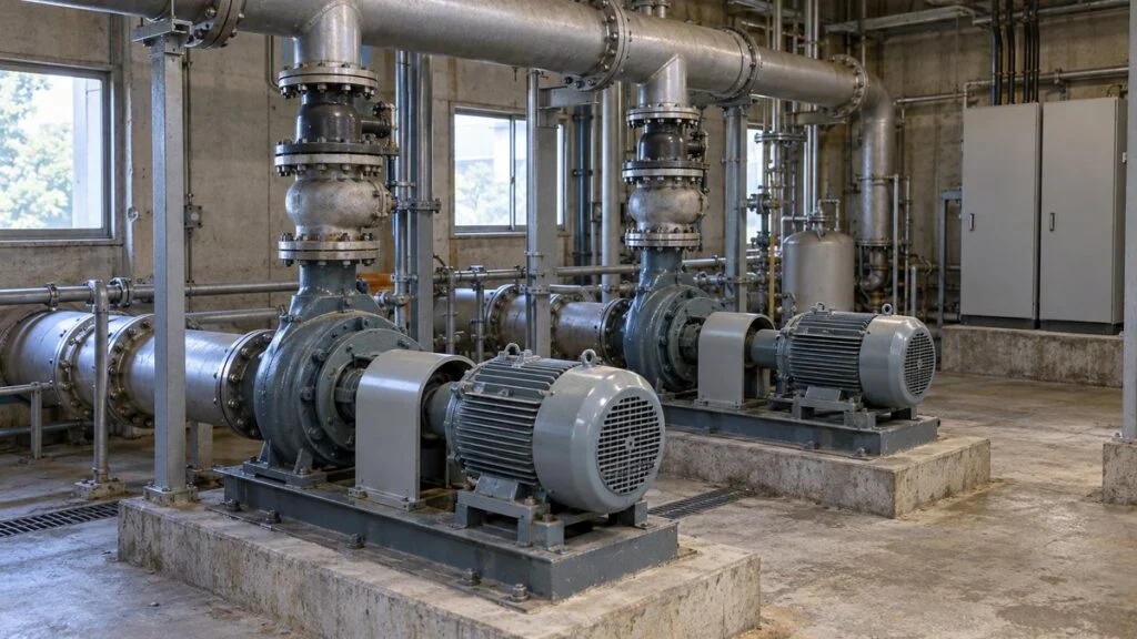
Picture a common situation: a line needs more water, so the plant installs a second pump, identical to the first, and ties both into the same discharge header. The expectation is simple: two pumps, twice the flow. In the worked example below, though, adding the second pump raises the total flow by only about 26.5%. That does not have to mean anything is wrong with the pumps; it is how pumps and piping interact.
The short answer: two identical centrifugal pumps in parallel do not necessarily deliver twice the flow of one pump in the same system. Running pumps in parallel means connecting them to a common discharge line so they share the required flow. The actual flow is set by where the combined pump curve crosses the system curve. In systems where the required head rises with flow, each pump is pushed back up its curve and delivers less than it did on its own, which limits the gain.
This guide covers why plants run pumps in parallel, a worked example with numbers, and four points to check: the common header, mismatched pumps, NPSH after one pump stops, and check valves. It ends with a checklist, questions to send to the pump supplier, and the limits of this approach. If you work from Japanese pump documents, the term table below will help you read them.
Terms You Will See on Japanese Pump Documents
Japanese datasheets, pump curves, and P&IDs (piping and instrumentation diagrams) use the following terms for the topics in this article.
| Japanese | Reading | English |
|---|---|---|
| 並列運転 | heiretsu unten | parallel operation |
| 直列運転 | chokuretsu unten | series operation |
| 全揚程 | zen-yotei | total head (H) |
| 吐出量 | toshutsu-ryo | flow rate, capacity (Q) |
| 抵抗曲線 | teiko kyokusen | system curve (system resistance curve) |
| 運転点 | unten-ten | operating point (duty point) |
| 締切運転 | shimekiri unten | shut-off operation (running at zero flow) |
| 逆止弁 | gyakushi-ben | check valve (non-return valve) |
| 軸動力 | jiku doryoku | shaft power |
| 必要NPSH | hitsuyo NPSH | NPSH required (NPSHR) |
| 台数制御 | daisu seigyo | pump staging (switching the number of running pumps) |
Contents
Why Run Centrifugal Pumps in Parallel?
Plants choose parallel operation when one pump cannot meet the required flow, or when they want to switch the number of running pumps to match demand. Each pump works against the same head, and the flows they deliver at that head add up. Parallel operation does not add heads the way a series connection does.
In series, you add each pump's head at the same flow. In parallel, you add each pump's flow at the same head. "Not enough head: go series. Not enough flow: go parallel" is a handy starting point, but in both cases the final flow and head depend on the system the pumps are connected to.
Running one pump during low demand and two during peak demand can be a better fit than running one large pump throttled back all the time. Pump efficiency and the control method also matter, though, so adding pumps does not guarantee energy savings by itself.
A second pump can also serve as a standby in case the first one fails. Alternating duty (one pump at a time) and assisted duty (both pumps running at peak demand) call for different pump capacities. Decide first whether you need full flow with one pump out of service, or only need to keep running at reduced flow.
Figure 1: Each pump discharges through its own branch before joining the common header
Two pumps sharing the flow. Arrows show the flow direction; each branch has one check valve. Scroll sideways to see the full figure.
The valve symbols only show where backflow is blocked. Isolation valves for maintenance, instruments, and drains are omitted.
In the basic arrangement, each pump has a check valve on its discharge, and the branches join the common header downstream of those valves. In a real plant, the suction piping layout, changes in liquid level, and branch lengths also affect how the pumps share the load. Placing two pumps side by side does not mean you can simply add their capacities.
How to Find the Real Flow: Combined Curve vs. System Curve
With two identical pumps, each pump delivers the same flow at any given head. To build the combined curve, double that flow at each head and connect the points. The answer you need is the new intersection of the combined curve with the system curve. Doubling the single-pump flow does not give you that answer.
Here is a fictional system to show the math. The single-pump curve is H = 40 − 0.005q², and the system curve (the head the piping requires) is H = 10 + 0.005Q². H is in meters, and flows q and Q are in m³/h. This simplified model ignores any difference in branch losses up to the point where the branches join.
Figure 2: On the same system curve, one pump gives 54.77 m³/h and two give 69.28 m³/h
Plot of the fictional model above. The two-pump curve stretches along the flow axis, and the operating point moves along the same system curve. Scroll sideways to see the full figure.
The values are intersections of the model. You cannot read a real pump's allowable flow, power, or NPSH from this graph.
One pump delivers about 54.77 m³/h (about 241 US gpm). Two pumps together deliver about 69.28 m³/h (about 305 gpm), an increase of only about 26.5%. Each pump now carries half of that, about 34.64 m³/h, which is less than it delivered alone. The gain is small because the head the system requires rises as flow increases.
In this example, the operating head rises from 25 m (about 82 ft) with one pump to 34 m (about 112 ft) with two. Parallel operation adds flows, not heads, when you build the combined curve, but that does not mean the operating head stays constant. The steeper the system curve, the less flow you gain by adding a pump.
In an actual installation, there are also losses between each pump's discharge flange and the common header. Compare the pumps at the common connection point. If the branches differ in size, length, or valves, even two pumps of the same model may not share the load equally, so include each branch path when you find the operating point.
Four Things to Check Before Running Pumps in Parallel
1. The Common Header May Need a Larger Bore
Downstream of the junction, the common header carries the combined flow of all branches, so review its size as needed. Parallel operation does not automatically call for a larger header. Decide based on the target flow, the margin in the existing piping, and the allowable pressure loss and velocity.
For example, if the actual flow doubles and the header bore stays the same, the average velocity doubles. Where the loss coefficient can be treated as constant, head loss is proportional to velocity squared, so it becomes four times larger. When you design for higher flow, watch for this sharp rise in header loss.
Figure 3: Check the header cross-section before doubling the flow
Illustrative comparison at the same length and conditions, with a constant loss coefficient. Whether you need a larger bore depends on the allowable loss and other factors.
Simplified sections showing bore vs. flow; the real velocity profile is not shown. Nominal pipe size and actual inside diameter differ.
To carry twice the flow at the same velocity, you need twice the cross-sectional area, which means about 1.414 times the inside diameter. That does not mean doubling the nominal size; compare actual inside diameters. Do not size the pipe on this calculation alone. Include length, roughness, fittings, valves, and installation conditions.
If pipe size, valve openings, and other conditions stay the same, adding a pump does not shift the system curve. The operating point simply moves to where the same system curve meets the two-pump combined curve. You redraw the system curve only when the resistance itself changes, for example after a pipe-size change or valve throttling.
On a retrofit where you cannot replace the header, calculate the flow you will actually reach with the added pump first and compare it with the flow you need. If an extra pump barely raises the flow, check whether pressure losses in the piping route, valves, or equipment are the real limit, and compare other options besides adding a pump.
2. Mismatched Pumps Can Run at Shut-Off
Some designs run pumps with different performance in parallel. If yours does, confirm that each pump can deliver positive flow against the common header pressure. Pumps with stable curves and similar shut-off heads are easier to combine. If the shut-off heads differ, check how the pumps share the flow across the whole demand range.
If the header pressure produced by one pump is higher than the pressure the other pump can develop at shut-off, the weaker pump's check valve stays closed. That pump keeps running but delivers nothing. Compare not only shut-off heads but also differences in suction pressure, branch losses, and the check valves' opening conditions.
Figure 4: The check valve stops backflow, but the weaker pump may still deliver no flow
Simplified section: the pressure the weaker pump can develop does not reach the header pressure, so the valve stays shut. Check the actual opening pressure differential in the valve specification. Scroll sideways to see the full figure.
Arrows show the direction of pressure, not actual flow from right to left. A check valve and minimum-flow protection serve different purposes.
At shut-off, part of the energy the pump puts into the liquid turns into heat, which can damage seals and internal parts. A motor that keeps turning while the pump delivers no flow is not normal operation and should not be left that way.
Zero flow is not the only risk. Also watch for operation below the manufacturer's minimum continuous flow and in unstable regions of the curve. Even pumps of the same model can perform differently if speed, impeller diameter, wear, or control settings differ, so matching nameplates alone is not enough.
When you add a pump, also consider whether you can measure the flow and discharge pressure of the existing and the new pump separately. Looking only at total flow can make you miss a pump that is carrying almost none of the load. Check each pump's motor current, vibration, and temperature as well.
3. NPSHA After One Pump Stops: It Depends on the Piping
There is no general rule that NPSHA drops when you switch to one pump. NPSHA (net positive suction head available) is a property of the installation. It depends on the pressure in the suction tank, the liquid level, the vapor pressure at the liquid temperature, and losses in the suction piping. Choosing a smaller pump does not lower it by itself.
What does matter is that the remaining pump's flow can increase after you go from two pumps to one. In the example above, each pump runs at 34.64 m³/h with two running, and the remaining pump jumps to 54.77 m³/h alone. Because the operating point moves, recheck the suction conditions, NPSHR (NPSH required), and power at that new flow.
Figure 5: After one pump stops, flow drops in the common suction line but rises in the running branch
Flows from the example above. Calculate the loss in the common line and in the running branch from their own flows, then add them to re-evaluate the suction loss. Scroll sideways to see the full figure.
This figure only sorts out the flow changes; it is not a simulation that includes suction losses. Whether NPSHA ends up higher or lower depends on the loss in each section, the liquid level, the liquid temperature, and other conditions.
In the suction branch leading to the remaining pump, loss can rise because that pump's flow increases. The common suction line, on the other hand, was carrying the combined flow of both pumps, so its loss falls when the total flow drops after the switch. Calculate the branch and the common line separately.
Whether NPSHA rises or falls after the switch therefore depends on the suction piping layout and the operating point. Also check cases where low liquid level, high liquid temperature, or a clogged strainer occur together. Confirm that NPSHA meets the manufacturer's NPSHR plus the specified margin with one pump and with several pumps running.
NPSHR is the NPSH the pump itself needs. When a catalog value is NPSH3, it corresponds to the test criterion of a 3% drop in head caused by cavitation. An NPSHA above that value does not guarantee that no vapor bubbles form at all. The required margin and operating range depend on the specific pump model.
Reducing the suction lift alone does not settle the question. Check the losses from the liquid surface to the pump inlet together with the temperature conditions.
Related: Cavitation vs Air Entrainment in Pumps: Telling Them Apart
4. A Check Valve on Each Pump Discharge
In parallel operation, put a check valve on each pump's discharge, upstream of the junction, to stop the running pump from pushing flow back into a stopped one. A single check valve after the junction cannot stop flow circulating from one branch to the other. On the piping drawing, confirm the flow direction and that each valve sits where it can isolate a stopped branch.
Backflow can cause abnormal conditions such as a stopped pump spinning in reverse. Where pumps differ in capacity or use speed control, check the common header pressure and the differential pressure across each pump. A check valve only prevents backflow. It does not solve a weak pump's lack of flow or shut-off operation.
(Reverse rotation from backflow is a different problem from a motor wired with the wrong phase sequence. For that case, see Pump Running Backwards? Phase Sequence and the Two-Phase Fix.)
The sudden change in velocity when a check valve closes also matters for water hammer. A loud bang at shutdown is not proof that the valve is working. Check the valve's closing characteristics and the conditions of the discharge line. For long lines or systems with large elevation differences, consider a transient (surge) analysis where needed.
If you combine speed control with pump staging, also check pressure conditions at start-up and shutdown, minimum flow at low demand, and how often pumps switch on and off.
Figure 6: Check one-pump, low-demand, and start/stop cases too, not just two pumps at peak demand
Items to check by combining the manufacturer's pump curves with the system conditions. Scroll sideways to see the full table.
| Operating case | What to check | Common mistake |
|---|---|---|
| Two pumps, peak demand | Intersection of combined and system curves, header loss, load sharing between pumps | Assuming total flow is twice the single-pump flow |
| One pump running | Remaining pump's flow, shaft power, NPSHR, branch loss | Assuming fewer pumps means less load on each pump |
| Low demand | Minimum flow, operation near shut-off, unstable region, start frequency | Missing that the weaker pump turns but delivers nothing |
| Start-up and shutdown | Backflow prevention, check valve closing, water hammer, control switchover | Assuming check valves alone solve transient problems |
For operating sequences, follow the equipment's instruction manual and your site's controlled operating procedures.
Checklist: Before You Add a Pump in Parallel
- Have you plotted the combined curve against the system curve and read the new total flow, instead of doubling the single-pump flow?
- Do you know the operating head with all pumps running, and is each pump still inside its allowable operating range at that point?
- Have you calculated the common header loss at the new total flow, using actual inside diameters, not nominal sizes?
- If the pumps differ (model, speed, impeller diameter, wear), can each one deliver positive flow at the header pressure across the full demand range?
- Is there a check valve on each pump's discharge, upstream of the junction?
- With one pump stopped, what is the remaining pump's flow, and are its shaft power, motor rating, and NPSHR acceptable at that flow?
- Have you calculated suction losses for the common suction line and each branch separately, including low liquid level, high temperature, and a clogged strainer?
- Is low-demand operation above the manufacturer's minimum continuous flow?
- Have water hammer and check-valve closing been reviewed for start-up, shutdown, and a pump trip?
- Can you measure flow, discharge pressure, motor current, vibration, and temperature for each pump separately?
Questions to Send the Pump Supplier or Japanese Engineering Team
If the pumps or the system design come from Japan, these questions help you get the data you need. You can paste them into an email as they are.
- Please send the H-Q, power, efficiency, and NPSHR curves for each pump, with impeller diameter and speed stated.
- Is the NPSHR on the curve NPSH3 (3% head drop)? What NPSH margin do you recommend for this application?
- What is the minimum continuous flow and the allowable operating range for each pump?
- Please share the system curve used for the design and the expected operating points for one pump and for two pumps running.
- Are the pumps intended for parallel operation, and are their curves stable with similar shut-off heads?
- What type of check valve is specified on each discharge, and what are its opening pressure differential and closing characteristics?
- Was a water hammer (surge) analysis done for start-up, shutdown, and pump trip? If so, please share the results.
- What start/stop sequence and staging logic do you recommend, including how the pumps switch at low demand?
Sample request: "We plan to run the two pumps in parallel on the existing header. Please send the pump curves (H-Q, power, NPSH3) for both units and the design system curve, and confirm the operating points, shaft power, and NPSHR with one pump and with two pumps running."
Limits of This Guide
- The worked example is a fictional, simplified model. It ignores differences in branch losses and does not represent any real pump or system.
- The size of the flow gain depends on the shape of the system curve. A steeper system curve tends to limit the flow gained by adding a pump.
- NPSH margins, minimum flow, and allowable operating ranges depend on the pump model. Use the manufacturer's data, not general values.
- Start-up and shutdown sequences, control settings, and surge protection are site-specific. Follow the equipment's instruction manual and your site's controlled procedures; this guide is not a work instruction.
- Energy savings from parallel operation or staging depend on operating hours, pump efficiency, piping losses, controls, and auxiliary equipment. Compare these case by case.
FAQ
Do Two Identical Pumps in Parallel Double the Flow?
Not necessarily. On the combined curve, the flow at any given head is twice that of one pump, but the actual operating point is where that curve crosses the system curve. In a system where the required head rises with flow, the total can fall well short of twice the single-pump flow. Calculate the flow per pump and the total flow separately.
Does the Head Stay the Same When Pumps Run in Parallel?
Not necessarily. "Adding flows at the same head" describes how you build the combined curve; it does not mean the operating head stays constant. The operating head depends on the system curve: if flow rises along it, the operating head changes too. In the fictional example above, it goes from 25 m with one pump to 34 m with two.
Can Pumps of Different Sizes Run in Parallel?
Sometimes, if the design allows it. You need to confirm positive flow, stability, and allowable range for each pump across the full demand range. If the header pressure exceeds what the weaker pump can develop, its check valve will not open and it will deliver zero flow. Do not pair pumps based on model names alone.
When One Pump Stops, Does the Load on the Other Drop?
Not necessarily. The remaining pump's flow can be higher than each pump's flow when both were running. Depending on the pump's power characteristics, the motor load can change too, so check shaft power and the motor rating at the single-pump operating point. Re-evaluate suction branch losses and NPSHR at that flow as well.
Does Running Pumps in Parallel Save Energy?
It can, if you can match the number of running pumps or their speed to changing demand. The actual annual savings depend on operating hours, pump efficiency, piping losses, controls, and auxiliary equipment. Adding a pump does not always cut power consumption.
Sources
- Combined curve, individual check valves, different shut-off heads and stability: KSB, "Parallel operation"
- System curve and the assumption that head loss varies with flow squared: KSB, "System characteristic curve"
- NPSHA vs. NPSHR, reference plane, NPSH3: KSB, "NPSH"; Hydraulic Institute, "The Basics of NPSH & Pump Operating Regions"
- Common discharge pipe and basics of parallel connection: Grundfos, "Pumps in parallel"
- Standby and assisted duty, alternating operation (product example): Grundfos, "SCALA1 twin pump configuration"
- Stable (continuously falling) H-Q curves and performance curves vs. flow: Torishima Pump, CAM/CAS catalog (Japanese)
- Start/stop transients, check-valve slam, and surge analysis: Ebara, water hammer analysis (Japanese)
Original article in JapaneseThis guide is adapted from a MONOSCOPE article written for readers in Japan: 渦巻ポンプの並列運転の注意点は?流量が2倍にならない理由・逆止弁とNPSH
About the editor
 MONOSCOPE EditorFOUNDER & EDITOR
Spent about ten years at a plant equipment maker and a plant engineering company, proposing, designing, and commissioning equipment, then moved into web marketing. Now a web consultant for B2B manufacturers, helping them explain their products and technology. Licensed in Japan as an Energy Manager and a Third-Class Chief Electrical Engineer.
Has run an engineering blog since 2017 (500+ articles) and a Japanese YouTube channel with about 20,000 subscribers. Each English guide is written from the Japanese shop-floor point of view and checked against the cited standards.