Pump Running Backwards? Phase Sequence and the Two-Phase Fix
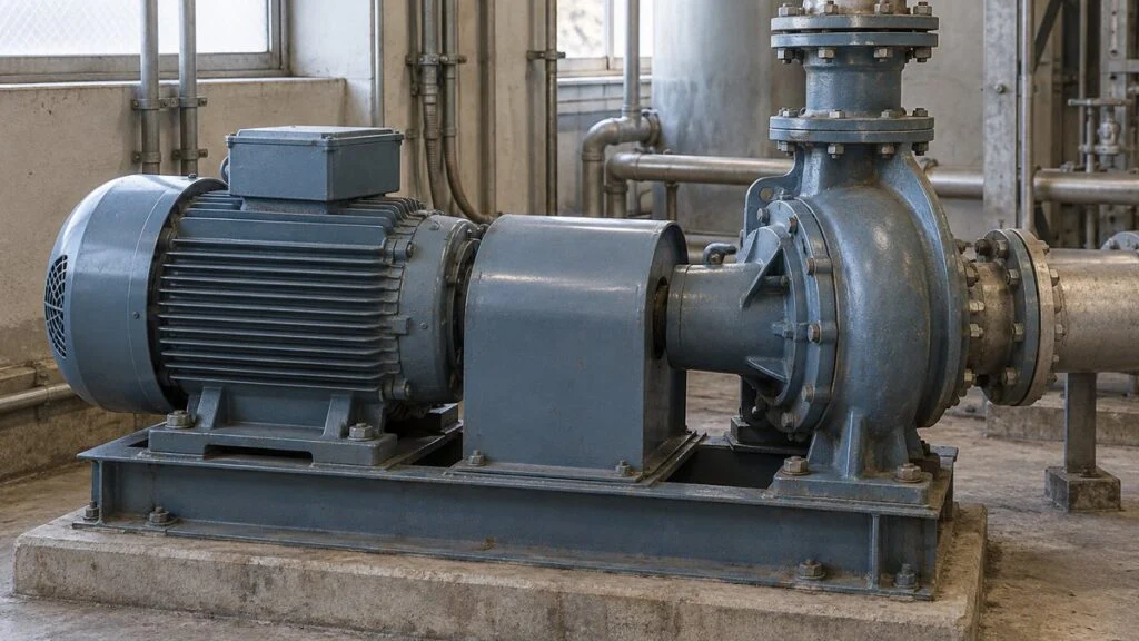
A centrifugal pump package from Japan is installed, wired, and ready for its first bump test. The motor starts, but the shaft turns against the arrow cast on the pump casing. Or a pump that ran fine for years starts running backward right after a motor or cable replacement. In both cases the electrician's usual answer is "swap two phases." That fix works for many pumps, but not for all of them, and knowing why it works tells you when it will not.
The short answer: a three-phase induction motor turns in the direction of the rotating magnetic field inside it, and that direction follows the phase sequence of the supply. When the motor runs direct-on-line from the mains, swapping any two of the three supply leads reverses the phase sequence, so the field and the shaft reverse too. The rule does not carry over to pumps fed by a variable frequency drive (VFD), to single-phase motors, or to a pump that spins backward after it stops because liquid flows back through it.
This guide covers the pump side, the motor physics, the two-phase swap, the cases where the rule breaks down, and a checklist plus a sample email for working with a Japanese supplier.
Contents
Why a Pump Runs in Reverse
A pump gives energy to a fluid and pushes it out. In a typical centrifugal pump, an impeller spins inside the casing and adds kinetic energy to water or another liquid. Impeller shapes vary by pump type; a centrifugal impeller and the screw-shaped rotor of a screw pump are different things.
In an electric pump, the motor supplies the torque that turns the impeller. When the motor is direct-coupled to the pump through a shaft coupling, a motor shaft that turns the wrong way turns the pump shaft the wrong way as well.
Figure 1: Motor rotation reaches the impeller through the coupling
Horizontal, direct-coupled pump. Schematic combining a section of the drive end with a front view of the impeller.
The impeller is shown face-on, in a different projection. On real equipment the coupling sits under a guard; suction piping, seals, and bearings are omitted.
When the impeller turns backward, the impeller and casing cannot produce the flow they were designed for, so head and flow fall short. How a given pump performs in reverse, and what reverse rotation does to its mechanical parts, depends on its design.
A trickle of water at the discharge does not prove the pump is turning the right way. On the other hand, low flow can also come from suction-side problems or higher system resistance. The pump performance curve shows what the pump should deliver, and NPSH tells you how much suction margin it has. Use both, and separate three things when you look for the cause: the power supply, the direction of rotation, and the fluid-side conditions.
Related: Centrifugal Pumps in Parallel: Why Flow Doesn’t Double
Related: Cavitation vs Air Entrainment in Pumps: Telling Them Apart
"Clockwise" Depends on Where You Stand
The same shaft looks clockwise from one end and counterclockwise from the other. Seen from the motor's drive (output) end and from the fan end, the direction appears reversed.
On site, use the rotation arrow on the pump and the viewing position stated in the instruction manual as the reference. A log entry that says only "turned clockwise" is hard to verify later.
Record where you viewed the shaft from as well as which way it turned, so mechanical and electrical staff mean the same thing. Do not remove the coupling guard while the pump is running just to get a better look.
How a Three-Phase Induction Motor Turns
A motor produces torque from the interaction between a magnetic field and current, the same idea behind the classroom magnet-and-coil experiment.
In a brushed DC motor with permanent magnets, reversing the armature current reverses the direction of rotation. That does not make "reverse the supply polarity and any motor reverses" a general rule.
Three-phase induction motors are widely used to drive pumps in factories and plants. To keep them apart from DC machines, the explanation below splits the motor into the outer stator and the inner rotor. In an induction motor, torque comes from current that is induced in the rotor conductors.
Time Shift of 120° vs. Winding Shift of 120°
Alternating current changes direction and magnitude in a regular cycle. A balanced three-phase supply carries three waveforms at the same frequency, each shifted 120° in time from the next.
One full cycle is written as 360°, so 120° is one-third of a cycle. At 50 Hz one cycle lasts 20 ms, and one-third of that is about 6.67 ms.
This 120° is a phase difference in time: it describes when current peaks in each phase.
Related: Japan Industrial Voltage: 200V 3-Phase and 50/60 Hz Guide
Figure 2: In a simple 2-pole model, the winding axes sit 120° apart
U, V, and W mark the magnetic axes of the winding groups. The figure does not show the actual number of coils or the terminal layout.
Real motors distribute the windings across many slots. In multi-pole machines the phases are 120 electrical degrees apart, which is not the same as dividing the circumference into three.
The stator also offsets the three winding groups in space. In a simplified 2-pole model, you can place the magnetic axes of the windings 120 mechanical degrees apart.
A real stator has many slots, and each winding is spread across several of them. It is not a tube with just three separate coils inside.
In 4-pole and 6-pole motors, the pole pattern repeats around the circumference, so 120 electrical degrees is not the same as 120 mechanical degrees around the stator.
Three Fields Combine into One Rotating Field
Current in each phase produces a magnetic field along the axis of its winding. Add the three together, and the direction of the combined field turns smoothly over time.
This is the rotating magnetic field. The motor does not switch one phase on at a time; all three currents change at once and together form a single combined field.
Figure 3 sets the U-phase current to its peak value of 1 at one instant. At that same instant, the V and W currents are not zero: each is 0.5 in the opposite direction.
Current in the opposite direction also flips the field that winding produces. The winding directions and the signs of the three currents together decide where the combined field points.
Figure 3: The combined field from all three phase currents
Same 2-pole model as Figure 2. Currents are shown as a ratio of the peak value; a minus sign means current flows the opposite way through the winding.
Idealized model with balanced sine waves and symmetrical windings. Upward is the positive y-axis; the figure does not define CW/CCW for any real motor.
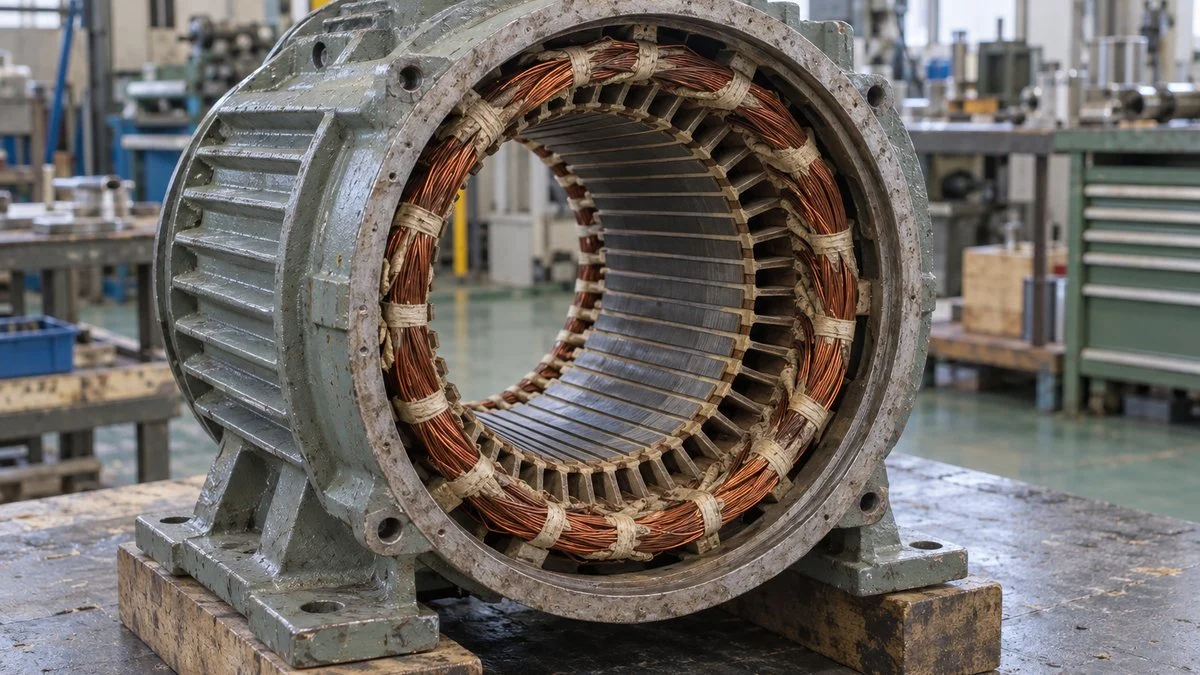
The rotor of a squirrel-cage induction motor has conductor bars joined at both ends by short-circuit (end) rings. Relative motion between the rotating field and these conductors induces voltage and current in the rotor.
That current, acting with the field, produces torque, and the rotor turns in the same direction as the field. The end rings tie the bars together electrically and give the rotor current a closed path.
Synchronous Speed vs. Shaft Speed
The speed of the rotating field is the synchronous speed, set by the supply frequency and the number of poles. When a normal induction motor drives a load, the rotor turns slightly slower than this.
That speed gap is what induces voltage in the rotor conductors. The gap expressed as a fraction is called slip. Slip is a separate quantity from the phase sequence, which sets the direction.
For example, a 4-pole motor on 50 Hz has a synchronous speed of 1,500 rpm. Assume a slip of 3% for illustration, and the rotor speed works out to 1,455 rpm.
Japan runs on 50 Hz in the east and 60 Hz in the west, so a motor shipped from Japan may be rated for a different frequency from your plant. See Japan Industrial Voltage: 200V 3-Phase and 50/60 Hz Guide for what to check. Frequency changes the speed, not the direction. When you select a motor, you also need the pump's shaft power, not just its speed.
Why Swapping Two Phases Reverses Rotation
Three-phase power has a phase sequence: the order in which the waveforms peak. With the stator windings unchanged, reversing the phase sequence reverses the direction in which the rotating field travels.
For example, if the order of waveforms reaching windings U, V, and W changes from U→V→W to U→W→V, the field turns the other way. Nothing moved inside the motor; only the mapping between the three supply waveforms and the windings changed.
Figure 4: Swapping just two connections reverses the phase sequence
Left: reference connection. Right: the phases going to V and W swapped (concept only).
The crossing is not a junction. This is not a guide to real terminals, wire colors, voltages, or wiring work; it shows only the phase sequence of a direct-on-line three-phase induction motor.
Swapping any one pair of phases reverses the sequence, and it does not matter which pair: leaving U in place and swapping V and W has the same effect as swapping any other pair.
Rotating all three leads by one position does not change the direction. That only changes where you start reading the sequence; the direction you travel around the circle stays the same.
Figure 5: The six possible sequences fall into two directions
Same stator, same viewing position, compared against ABC as the reference.
| Sequence | Compared with reference | Why |
|---|---|---|
| ABC, BCA, CAB | Same direction | A different starting point, but the same A→B→C cycle |
| ACB, CBA, BAC | Opposite direction | Swapping two phases reverses the cycle |
The label "ABC" alone does not define clockwise for every motor. The winding definitions and the viewing position must match too.
On Japanese drawings and test instruments you will often see the supply lines labeled R, S, T and the motor terminals labeled U, V, W, while US practice uses L1, L2, L3 and T1, T2, T3. A Japanese phase sequence indicator, called a kensoki (検相器), typically lights a seiso (正相, positive sequence) or gyakuso (逆相, negative sequence) lamp. Confirm the labeling in the legend of the actual wiring diagram rather than assuming it.
Reversed Sequence vs. Lost Phase
Keep phase reversal and phase loss apart. In a reversal, all three phases are present but in the opposite order. In a phase loss (single phasing), one of the three phases is missing.
A lost phase can stop the motor from starting, unbalance the currents, or cause overheating. Treating "it won't turn, so swap two leads" as a fix misses a missing supply phase or a bad connection.
Even with the correct sequence, a motor may fail to start if the shaft is locked or the pump load is too heavy. Treat "turns the wrong way" and "does not turn" as two different problems.
Running current says something about the load, but current alone does not tell you the direction. Record phase sequence, shaft movement, and piping conditions as separate observations to avoid mixing up causes.
Changing the phase sequence on the supply side also reverses every other direct-on-line motor fed from that point. Use the single-line diagram and schematics to define the scope of any change and manage the effect on equipment outside it.
When Swapping Two Phases Does Not Apply
VFD-Driven Pumps
This section covers a common voltage-source VFD with a rectifier and a DC bus. The drive converts the incoming AC to DC and then builds a new three-phase output, so changing the input phase sequence does not change the direction of the motor.
Figure 6: A VFD builds a new three-phase output
Concept of a typical rectifier, DC bus, and inverter output stage.
Blocks are functional; the parallel lines on the DC bus represent capacitors. Actual components, terminals, and any line bypass circuit are omitted.
When a VFD-driven pump runs backward, check the forward/reverse command, the operating mode, and the output phase sequence separately. A panel showing "FWD" (in Japanese, seiten, 正転) does not guarantee the pump turns the way it needs to.
If the system has a bypass that switches the motor to line power, the supply path differs between drive operation and line operation. Correct rotation in one mode says nothing about the other; check both.
The direction command travels through the control panel wiring and, in many systems, a PLC. For diagnosis, trace the command back to its source and match it against what the shaft actually does.
Related: Japanese Machine Control Panels: UL 508A, NFPA 79, and CE
Related: How to Read Japanese PLC Programs: Mitsubishi X/Y/M/D
Single-Phase Motors
In a single-phase motor, the direction is set by how the main winding, auxiliary winding, and capacitor are arranged. Swapping the two supply wires does not reverse it the way swapping two phases reverses a three-phase motor.
Any actual rewiring is for the person responsible for the equipment and qualified workers to carry out under the manufacturer's procedures. Besides isolating the supply, preventing restart, and verifying the absence of voltage, work on VFD-fed equipment also requires precautions against residual voltage in the drive.
Reverse Spin After Shutdown (Backflow)
After a pump stops, liquid can flow back from the discharge side, push the impeller, and spin the shaft backward. The energy for this comes from the liquid's pressure or elevation, not from the electrical supply.
Whether the pump turns backward from the moment it starts or only after power is cut changes what you investigate. Restarting a pump while it spins in reverse loads the pump and motor, so avoid diagnosing by repeated start attempts.
For reverse spin after shutdown, look at discharge pressure, elevation differences in the piping, and check valves. Swapping phases does nothing about the pressure difference that drives the liquid back.
In systems with several pumps, the piping between stopped and running pumps also matters. When the control system changes the number of running pumps, look at those changes and the hydraulic layout together.
The pump type and the fluid matter too. Vacuum pumps that handle air, and pumps chosen for viscous liquids, have different internal designs and different permitted operating conditions.
After the Fix: Drawings and Records
Once the phase sequence has been changed, bring the wire numbers, terminal assignments, and wiring diagrams in line with the actual installation. If the numbers stay as they were, the next replacement job can repeat the same fault.
A record means more when it includes the equipment tag, motor model, drive type, required pump direction, and viewing position. For VFD-driven equipment, also log the command source and any parameter changes.
If the pump ran correctly before a job and backward only afterward, the connections that the job touched are the best lead. Recording motor replacement, cable replacement, and panel upgrades separately gives everyone the same starting point for the investigation.
Do not infer the connections from wire color or appearance alone; check them against the equipment drawings and the actual markings. A change history lets the next inspection start from the last known-good state.
After the fix, do not stop at "it turns the right way." Evaluate flow, head, current, and vibration under the specified operating conditions. If performance is still short after the direction is corrected, look for other causes such as suction conditions or system resistance.
Checklist: Wrong Rotation on a Japanese Pump
Use this list to sort out the facts before anyone changes wiring. It is a fact-finding aid, not a work procedure; the person responsible for the equipment decides what to do.
Reverse-rotation fact-finding checklist
| Item | What to confirm |
|---|---|
| Required direction | Arrow on the pump casing and the viewing position in the manual (drive end or fan end) |
| When it turns backward | From start-up, or only after shutdown (backflow) |
| Drive type | Direct-on-line or VFD; whether a line bypass exists |
| Supply sequence | Phase sequence indicator reading at the measuring point, and where that point is |
| All phases present | No missing phase or loose connection before anyone swaps leads |
| Labels and drawings | R/S/T and U/V/W (or L1–L3, T1–T3) as defined in the drawing legend |
| Scope of any change | Other direct-on-line motors fed from the same point |
| VFD settings | FWD/REV command source, operating mode, output wiring |
| Recent work | Motor, cable, or panel replacement since the last correct run |
| After correction | Flow, head, current, vibration; updated drawings and wire numbers |
Questions for the Japanese Supplier
- From which end is the rotation arrow on the pump meant to be viewed?
- Which supply terminal should connect to which motor terminal for the required direction, and is that shown on a drawing?
- Is reverse rotation during a short bump test acceptable for this pump, including its mechanical seal and bearings?
- For VFD units: which parameter or input sets forward/reverse, and has it been set at the factory?
- Does the system need a check valve or other protection against reverse spin after shutdown?
- Is the motor rated for our supply frequency (50 Hz or 60 Hz)?
Sample Email to the Supplier
Subject: Pump P-101 rotation direction at commissioning
During the first run of pump P-101, the shaft turned opposite to the arrow on the casing (viewed from the motor fan end). The motor is started direct-on-line, and all three phases were present. Before we change any connections, please confirm (1) which end the arrow should be viewed from, (2) the required connection between supply terminals R/S/T and motor terminals U/V/W, and (3) whether the brief reverse run may have affected the mechanical seal. A wiring diagram showing the intended phase sequence would also help.
The pump tag, viewing end, and starting method above are fictional; replace them with your own details.
Limits of This Guide
- The two-phase rule covers three-phase induction motors started directly from the mains. It does not cover VFD-driven motors, single-phase motors, or reverse spin from backflow.
- Figures are idealized models. They do not define clockwise or counterclockwise for any real motor, and they are not wiring instructions.
- Terminal labels, wire colors, and phase sequence conventions vary by country, company, and drawing. Always follow the legend on the project's drawings.
- How much reverse rotation a pump tolerates depends on its design. Ask the manufacturer.
FAQ
Why does swapping two phases change the direction but not the speed?
Because it reverses the phase sequence, which reverses the direction of the rotating field. With the same frequency and number of poles, the synchronous speed stays the same; only the direction flips.
Will a motor run backward if the frequency changes from 50 Hz to 60 Hz?
No. Frequency affects the synchronous speed; the phase sequence decides the direction. Whether a given motor and pump can run on another frequency depends on both of their specifications.
If a phase sequence tester shows the sequence, is the pump direction confirmed?
Not by itself. The tester shows the sequence at the point you measured. You still need to check the connections from there to the motor, the winding definitions, whether a VFD is involved, and the viewing position against the pump's required direction.
Can I keep running a pump backward if it still delivers some water?
No. Some discharge does not show that the pump meets its design performance or that it is mechanically sound. Correct the cause using the manufacturer's specified direction, then evaluate performance under the specified conditions.
Why does the panel say "FWD" when the pump turns against its arrow?
"Forward" is a name for a control command. The actual direction also depends on the output phase sequence and how it maps to the windings. Match the command name, the wiring diagram, and the viewing position to the direction the pump requires.
Sources
- Phase sequence and rotation of three-phase motors, distinction from single-phase: Oriental Motor, AC motor operating manual
- Stator windings, combined field, poles and speed: EE2E11 Electrical Energy Conversion, "AC Machine Stator"
- Induced current and slip: EE2E11 Electrical Energy Conversion, "Induction Machine"
- Armature current and torque in permanent-magnet DC machines: EE2E11 Electrical Energy Conversion, "DC Machines"
- Synchronous speed: Mitsubishi Electric FA FAQ (Japanese)
- Changing motor rotation direction on an inverter: Toshiba Industrial Products and Systems FAQ (Japanese)
- Drive input phase sequence: Schneider Electric FAQ FA23680
- Phase sequence indicators (kensoki) and motor direction: Panasonic TERASU glossary (Japanese)
- Reverse rotation from backflow: KSB, "Reverse Running Speed"
Original article in JapaneseThis guide is adapted from a MONOSCOPE article written for readers in Japan: ポンプが逆回転する理由|三相モーターの相順と2相を入れ替える原理
About the editor
 MONOSCOPE EditorFOUNDER & EDITOR
Spent about ten years at a plant equipment maker and a plant engineering company, proposing, designing, and commissioning equipment, then moved into web marketing. Now a web consultant for B2B manufacturers, helping them explain their products and technology. Licensed in Japan as an Energy Manager and a Third-Class Chief Electrical Engineer.
Has run an engineering blog since 2017 (500+ articles) and a Japanese YouTube channel with about 20,000 subscribers. Each English guide is written from the Japanese shop-floor point of view and checked against the cited standards.