Cavitation vs Air Entrainment in Pumps: Telling Them Apart
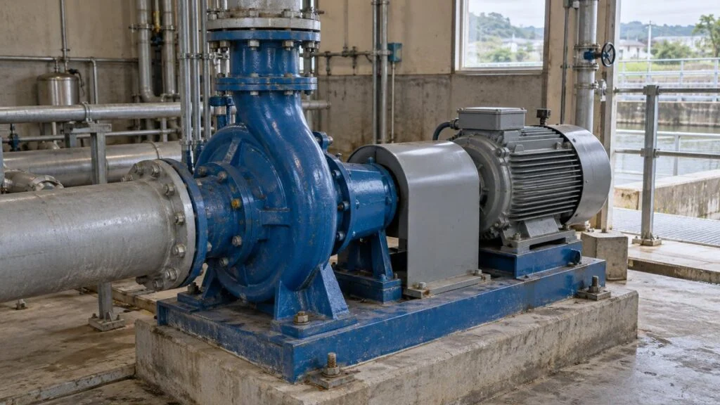
A centrifugal pump on your line starts to rattle and vibrate, and flow drops. The maintenance log from the Japanese side, or the supplier's service engineer, writes it up as either kyabiteshon (キャビテーション, cavitation) or ea-gami (エア噛み, literally "air biting," meaning air entrainment or air binding). Both cause noise, vibration, and lost flow, so the two are easy to mix up. They have different causes, and they call for different checks and fixes.
The short answer: cavitation is the liquid itself turning to vapor where pressure is low, while air entrainment is outside air getting into the pump with the liquid. The bubbles form in different places and come from different causes, so you need different checks to find them. Do not decide by sound alone. Look at liquid temperature, suction pressure, and the liquid level in the tank, and run two checks side by side: one that hunts for where air gets in, and one that calculates how close the liquid is to boiling.
This guide covers ordinary centrifugal pumps. It treats cavitation as mainly vapor bubbles and air entrainment as air coming from outside the liquid. It compares where the bubbles come from, shows a worked NPSH example, and ends with a record sheet, questions for the pump supplier, and the limits of this approach.
Contents
What Is Cavitation?
Cavitation happens when pressure in the flow drops far enough for part of the liquid to vaporize and form bubbles. When those bubbles are carried into higher pressure downstream, they collapse suddenly and send shocks and noise into the surroundings.
The key point: the liquid does not have to be heated to its boiling point. If the pressure drops locally, for example at the impeller eye (inlet), even water at room temperature can vaporize there.
Figure 1: Vapor Bubbles Form at the Impeller Eye and Collapse Near the Wall
Bubbles form in the low-pressure zone. Erosion happens where the collapsing bubbles act on the wall.
Schematic only. The number of bubbles and where they collapse depend on the actual flow, speed, and impeller design.
When this collapse repeats near the impeller surface, it wears away the metal (cavitation erosion). Besides heavier vibration, it damages the vanes and lowers the pump's head, so do not ignore the signs.
The basic way to prevent it is to give the suction side enough pressure margin. That means raising the liquid level, reducing suction-pipe resistance, and keeping the operating flow within the pump's proper range.
A clogged suction strainer lowers the pressure downstream of it and makes cavitation more likely. Mesh size is only part of it: how the strainer is selected and how its differential pressure is monitored also decide whether the suction conditions hold.
Surging, a periodic swing in flow and pressure, can cause similar vibration. It occurs under different conditions, so the symptom of vibration alone does not tell you which fix to apply.
In its early stages, cavitation can occur while the pump still delivers its normal flow. Water coming out does not mean the pump is fine. Record noise and suction pressure at the same flow over time to catch the early signs.
What Is Air Entrainment (Ea-gami)?
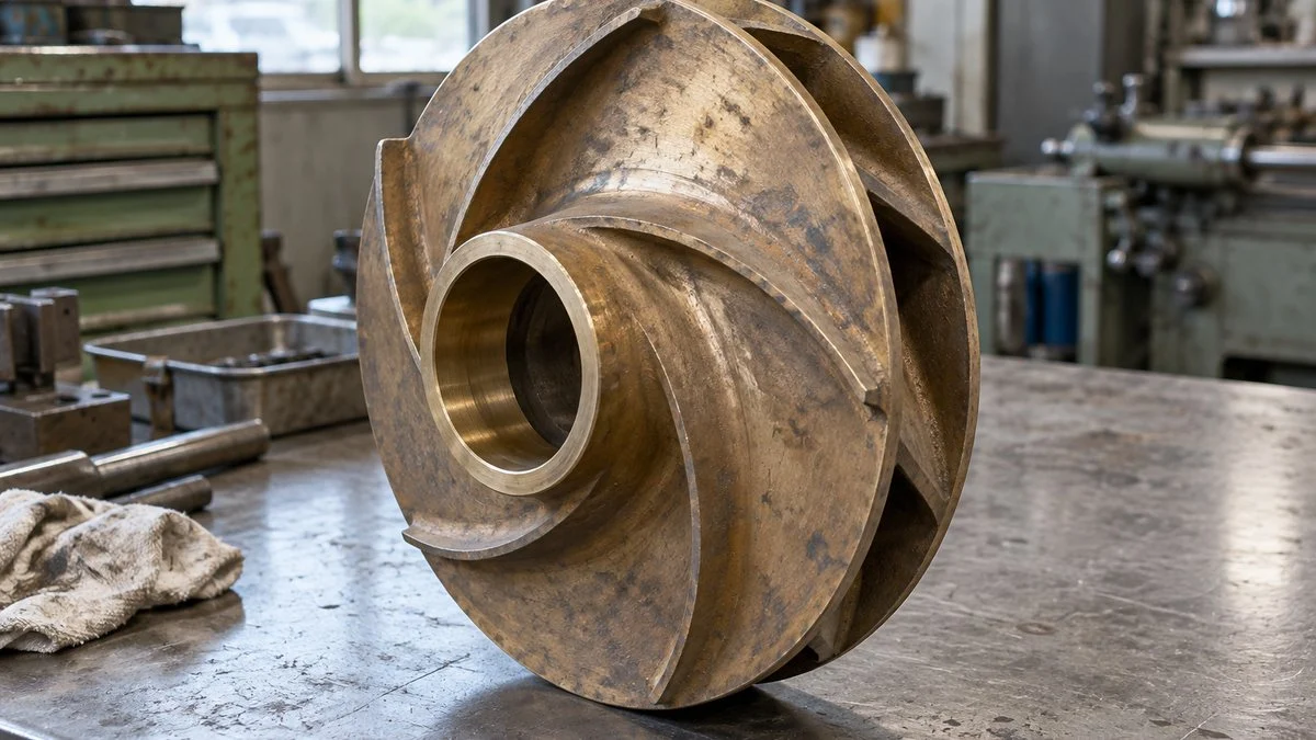
Air entrainment is when air enters along with the liquid and the pump can no longer deliver a steady flow. The air comes from pockets in the suction piping or is drawn in from the tank surface, then carried into the impeller. Japanese plant staff call this ea-gami.
A centrifugal pump builds pressure by giving the liquid velocity, so gas collecting inside it cuts its pumping capacity. Symptoms range from unsteady running with a small amount of air to a pump that moves no water at all because an air pocket has formed (air binding).
Figure 2: How Air Gets In From the Surface and Through Suction Joints
Check separately for air-drawing vortices in the tank and for gaps in piping that runs below atmospheric pressure.
Leaks at joints matter in sections where the internal pressure is below atmospheric. You may see no water leaking at all.
When the suction side runs below atmospheric pressure, air can be pulled in through gaps at joints or the shaft seal. A joint that does not drip when the pump is stopped can still suck in air under vacuum while it runs, so check for that too.
In the tank, a low liquid level or uneven inflow can create a vortex that pulls air all the way down to the suction inlet. Ebara's sump analysis material also stresses shaping the sump and controlling inflow to suppress harmful vortices.
If the pump moves no water only right after start-up, check for insufficient priming (yobimizu, 呼び水) and for air trapped at high points in the piping. Fill the pump with liquid when priming and remove remaining air through the vent points designed for it, following the specified procedure.
Air entrainment does not always raise motor current. With less liquid to move, the load can fall and the current can drop. Compare flow and current together against normal readings.
Low current does not mean the pump is safe. Parts cooled by the pumped liquid, such as the shaft seal, can still be damaged.
Blaming all dry-running damage on motor overload leads to the wrong cause. Poor lubrication in a wet-rotor pump and poor shaft-seal cooling in an ordinary pump damage different parts and call for different protection.
Venting the air is not the end of the fix. Find and repair the point where air gets in. Improving level control and restoring the airtightness of the piping are different kinds of work, so a record of when the problem occurs helps decide which is needed.
During inspection, trace the piping from the tank to the pump on the drawings and look for high points where air can collect. If the symptoms started after a piping modification, changes in slope or vent locations are good leads.
Venting must follow the shutdown, cool-down, and depressurizing steps specified for the pump model, and a recovery method that suits the liquid. Do not loosen joints on a running pump, and do not operate air vents that the instruction manual says must not be opened during operation.
In closed heating or chilled-water loops, trapped air shows up differently. See Hot Water Loop Not Flowing? Check Fill, Air, Valves, Pump. If a pump delivers little flow right after installation or motor work, also rule out reverse rotation: Pump Running Backwards? Phase Sequence and the Two-Phase Fix.
How to Tell Cavitation From Air Entrainment
Start by comparing the conditions that changed. Take the liquid level, liquid temperature, flow, and speed at the time the problem appeared, and compare them item by item with your normal-operation records.
If the problem appears only after the tank level has dropped, a falling level may be the common trigger. A lower level both reduces NPSHA and makes air-drawing vortices more likely, so follow up on both causes.
Also note whether the problem started right at start-up or suddenly during steady running. For the first, check filling and venting first. For the second, check changes in level or temperature and rising suction resistance first.
If heavy vibration or a total loss of flow continues, stop the pump using the plant's shutdown procedure. Avoid repeated starts or dry running just to find the cause. Before disassembly, isolate power and release residual pressure under your site's procedures.
Check 1: Can Local Pressure Fall to the Vapor Pressure?
To judge how close the liquid is to vaporizing, do not look at temperature alone. Use the saturation vapor pressure at that temperature and ask whether pressure inside the pump can fall that low.
Hot water has a higher vapor pressure than cold water, so at the same suction pressure it has less margin before it vaporizes. Even room-temperature water can form vapor bubbles at the low-pressure zone of the impeller eye if the suction lift or pipe losses are large.
Figure 3: Local Pressure Along the Flow vs. Vapor Pressure at That Temperature
Even if the suction gauge reads above vapor pressure, pressure falls further at the impeller eye.
Conceptual diagram at constant liquid temperature. Pressure values and positions are not to scale. Distinguish the local pressure where bubbles form from the pressure at the measuring point.
For liquids other than water, such as solvents, use property data for the actual components at the actual temperature. Looking at vapor pressure at the operating temperature tells you more about suction conditions than comparing atmospheric boiling points.
Most pressure gauges read gauge pressure, the difference from atmospheric pressure. Comparing with vapor pressure requires absolute pressure, so understand how the compound gauge scale (vacuum and pressure on one dial) relates to absolute pressure and convert.
If the problem appears only on days when the liquid is warmer, look into the effect of higher vapor pressure. If it appears right after topping up the tank or at low tank level, check for air being drawn in from the surface as well.
Gas dissolved in the liquid can also come out of solution as bubbles when pressure drops. In real pumps, vapor and gas effects overlap, so visible bubbles alone do not prove the air came from outside.
Check 2: Is There Enough NPSH?
NPSH (net positive suction head) expresses, as a head, how much pressure margin the suction side has above the pressure at which the liquid vaporizes. It is given in meters, but it is not a pipe length. It is a pressure margin converted into a height of liquid.
The value the installation can provide is NPSHA (NPSH available). The value the pump needs is NPSHR (NPSH required). The basic check is to compare the installation's calculated NPSHA with the manufacturer's NPSHR at the same flow and speed.
NPSHR changes with the operating point, so checking only at rated flow can miss a shortfall. Read the actual flow against the pump's performance curve and operating point.
Related: Centrifugal Pumps in Parallel: Why Flow Doesn’t Double
Use the actual liquid level when the problem occurred, not the usual average level. When checking the design, also include the lowest expected level and the most severe temperature, and make the difference from normal operation clear.
Suction losses include not only straight pipe but also elbows, valves, strainers, and other fittings. Calculating separately for a freshly cleaned strainer and a partly clogged one shows how your maintenance criteria affect suction conditions.
Figure 4: Head Balance When Lifting From an Open Tank
Start from the difference between atmospheric pressure and vapor pressure, then subtract the suction lift and suction-pipe losses.
Assumed values for illustration (2.3 kPa is roughly the vapor pressure of water at 20°C / 68°F). Velocity at the tank surface is ignored; density 1,000 kg/m³ and g = 9.81 m/s².
In this example, a further drop in liquid level lowers NPSHA, and so does any increase in pipe losses. Looking at each term of the equation lets you tie what changed on the day of the problem to a specific condition in the installation.
With the same assumptions, a 1 m drop in the liquid level takes NPSHA from 6.59 m to 5.59 m. If the suction loss also rises by 1 m, NPSHA falls to 4.59 m, and the margin over the 4 m requirement shrinks sharply.
Where a falling level and fouling progress together, build that combination into the inspection plan. For example, compare suction pressure at the lowest level before and after strainer cleaning to see whether cleaning has brought the strainer's pressure drop back to normal.
Conversely, lowering the pump increases the height of liquid pushing into the suction (positive suction head).
If you measure pressure at the pump suction flange during operation, you also need to account for velocity head and the height of the measuring point. Mixing the tank-based equation with the suction-flange-based one can make you subtract height or losses twice.
A catalog value labeled NPSH3 is the NPSH at which cavitation reduces the pump's head by 3%. It is not the point where bubbles first form, so NPSHA above NPSH3 does not guarantee that no cavitation occurs.
Enough NPSH does not close the air question: paths for outside air may still exist, so continue checking for air entrainment. Recheck the calculation under conditions that include the lowest level, the highest liquid temperature, and the maximum flow, and inspect both airtightness and surface vortices.
If adjusting a valve changes the symptoms, record the new flow and suction pressure together. Throttling the suction valve worsens suction conditions, so do not use it casually as a diagnostic step, and keep the pump within its allowable operating range.
Figure 5: From Symptoms to What to Check and How to Fix It
Base the fix on which conditions changed, not on what the noise sounds like.
The two can occur at the same time. Mechanical vibration and pipe-support problems are also possible, so do not force an either-or answer.
After the Fix: Confirm the Result and Prevent Recurrence
After the work, do not stop at "it's quieter now." Check that flow and discharge pressure are back to normal. Checking power as well helps you tell apart a fix that restored pumping from one that only reduced the load.
To evaluate power and flow, start from the relationship between the pump's shaft power and hydraulic power. Even with no flow at shut-off (closed discharge), heat keeps building inside the pump, so manage the temperature rise from running against a closed valve as a separate problem.
Once you know the conditions under which the problem recurs, you can revise the low-level alarm setting or the strainer-cleaning criteria. Feed the records into condition-based maintenance so the problem does not return under the same conditions. For how Japanese plants frame this, see TBM vs CBM: Time-Based vs Condition-Based Maintenance.
When you pass records to the manufacturer, include the pump model, impeller diameter, and speed so the conditions can be pinned down. The same model can have a different performance curve with a different speed or impeller, so check the actual nameplate against the documents.
If the problem persists, widen the search to mechanical causes such as bearings, alignment, and pipe supports. Do not assume one of these two bubble-related phenomena must be the answer; look for a cause that matches both the operating data and the inspection findings.
Pumps running side by side add their own suction and flow questions. See Centrifugal Pumps in Parallel: Why Flow Doesn't Double.
Checklist: What to Record When a Pump Acts Up
- Date, time, and whether the problem started at start-up or during steady running
- Liquid level in the suction tank, with the reference elevation (datum) it is measured from
- Liquid temperature, and the liquid's vapor pressure at that temperature (for non-water liquids, the property data used)
- Suction and discharge pressure, stating gauge or absolute and where each gauge is mounted
- Flow, pump speed, motor current, and power, compared with normal-operation readings
- Strainer differential pressure and the date of the last cleaning
- Recent events: tank top-up, piping modifications, valve position changes, priming or venting
- Whether a vortex is visible at the tank surface, and whether bubbles appear when the tank is filled
- Pump model, impeller diameter, and speed from the nameplate
- Calculated NPSHA at the actual flow and lowest level, against NPSHR read from the manufacturer's curve
Questions for the Pump Supplier
- What is NPSHR at our actual flow and speed? Is the catalog value NPSH3, and what NPSH margin do you recommend for this service?
- What is the allowable operating range (minimum and maximum flow) for this impeller diameter and speed?
- What minimum liquid level or submergence do you recommend above the suction inlet to avoid air-drawing vortices?
- Where are the designated vent points, and in what state (stopped, cooled, depressurized) may they be opened?
- What priming procedure does the instruction manual specify, and how is the pump protected against dry running?
- Does motor current or power rise or fall when this model loses prime? Which signal do you recommend for dry-running protection?
Sample request: "Pump P-101 shows noise and a flow drop when the suction tank level is low. Attached are our readings for level, liquid temperature, suction and discharge pressure, flow, speed, and current. Please send the H-Q and NPSH3 curves for the installed impeller diameter, confirm NPSHR and the recommended NPSH margin at our operating point, and advise the minimum liquid level above the suction inlet."
(The pump tag and readings in the sample are fictional.)
Limits of This Guide
- The NPSH example uses assumed values for illustration. It does not represent any real pump or system.
- Cavitation and air entrainment can occur together, and mechanical causes (bearings, alignment, pipe supports) can produce similar vibration.
- NPSH margins, operating ranges, venting, and dry-running protection depend on the pump model. Use the manufacturer's data and instruction manual, not general values.
- Shutdown, isolation, depressurizing, and venting are site-specific safety tasks. Follow your plant's controlled procedures; this guide is not a work instruction.
- This guide covers ordinary centrifugal pumps. Positive-displacement pumps, self-priming designs, and pumps for volatile or hazardous liquids need checks beyond those here.
FAQ
Can You Tell Cavitation From Air Entrainment by Sound Alone?
It is hard to be sure from sound alone, because both cause noise, vibration, and lost pumping capacity. Record the flow and liquid level at which the noise appears, then evaluate NPSH from suction pressure and liquid temperature to narrow down the cause.
If Venting Fixes It, Was Air the Cause?
It is a clue that trapped air played a part, but if air collects again, you still need to remove the source. Separate insufficient filling at start-up from air drawn in during operation, and record how long the pump stays stable after venting.
Can Cavitation Happen With Cold Water?
Yes. It occurs whenever local pressure drops to the saturation vapor pressure at that temperature. Do not rule it out based on temperature alone; evaluate suction conditions from the suction lift, pipe resistance, and actual operating flow.
Will Installing an Air Vent Valve Prevent Recurrence?
Not by itself. Besides a way to discharge air, you need to remove the cause of air getting in. Where piping runs below atmospheric pressure, outside air can be drawn in, including through the vent, so the valve's location and specification have to be designed for the piping conditions.
Is NPSH3 the Point Where Cavitation Starts?
No. NPSH3 is the NPSH at which the head drops by 3% due to cavitation. Bubbles begin to form at higher NPSH than that, so NPSHA above NPSH3 does not mean the pump is free of cavitation.
Sources
- NPSH equations referenced to the tank and to the suction flange, datum, pipe losses, operating point and NPSHR: KSB, "NPSH"
- Bubble collapse, NPSH3 vs. inception, overlap of gas and vapor: KSB, "Cavitation"
- Conditions for cavitation, occurrence at room temperature, vibration, lost capacity, erosion: Ebara, cavitation-related technology (Japanese)
- Air-drawing vortices and inflow conditions in pump sumps: Ebara, pump sump vortex flow analysis (Japanese)
- Investigating air intake and air lock, and safe handling: Ebara, AAB instruction manual (Japanese)
- Bearing and shaft-seal damage from dry running, detection by level or suction pressure: Grundfos, dry-running protection
- Example of dry-running protection based on a drop in power (protection methods and settings vary by model): Grundfos FAQ, SQ/SQE dry-running protection
- Poor cooling and lubrication of rotating parts in wet-rotor pumps: Grundfos FAQ, dry running and inadequate lubrication in wet-running pumps
Original article in JapaneseThis guide is adapted from a MONOSCOPE article written for readers in Japan: キャビテーションとエア噛みの違い|ポンプの症状・原因と見分け方
About the editor
 MONOSCOPE EditorFOUNDER & EDITOR
Spent about ten years at a plant equipment maker and a plant engineering company, proposing, designing, and commissioning equipment, then moved into web marketing. Now a web consultant for B2B manufacturers, helping them explain their products and technology. Licensed in Japan as an Energy Manager and a Third-Class Chief Electrical Engineer.
Has run an engineering blog since 2017 (500+ articles) and a Japanese YouTube channel with about 20,000 subscribers. Each English guide is written from the Japanese shop-floor point of view and checked against the cited standards.