Hot Water Loop Not Flowing? Check Fill, Air, Valves, Pump
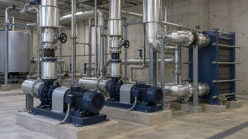
The circulator pump is running, the motor is drawing current, and the pressure gauges show numbers. Yet the radiators, coils, or process heat exchangers at the far end of the hot water loop stay cold. You may face this during commissioning of a closed hot water system, whether it was designed by a Japanese contractor, built around Japanese pumps and heat exchangers, or handed over with a Japanese test sheet full of terms like jusui (filling) and ea-nuki (air venting).
The short answer: a pump that turns is not the same as the right amount of hot water reaching the loads. When a hot water loop is not flowing, check the causes in order: makeup water and filling, closed valves, pump rotation, objects left in the line, trapped air, and only then whether the pump suits the circuit. And keep two pressures apart: the static pressure that keeps the loop full, and the differential pressure the pump needs to push water around it. In a full, closed loop, the building height is not added to the circulator head.
This guide walks through the six causes, works through a static pressure and pump head example, lists what to record during commissioning, and ends with a checklist and questions for the equipment supplier.
Contents
First, Separate "No Flow" from "Flow but No Heat"
Before touching any valve, decide which problem you have: is the loop water not circulating at all, or is it circulating without delivering heat? Record the flow rate, the supply and return temperatures, and the pump suction and discharge pressures at the same time. Readings taken together narrow the search far more than any single gauge.
This guide covers closed hot water circulation loops, such as those in hospitals, hotels, and factories, where water heated in a heat exchanger goes out to the loads and comes back to be reheated. Keep these loops separate from piping that replaces water drawn off for domestic hot water use, and from circuits that transfer water to a separate open tank. Before you start, trace the system diagram: where water enters and leaves, where the expansion tank connects, where the pump sits, and the return path from each load.
Six Causes to Check, in Order
1. Makeup Water Is Not Filling the System
After a new installation or after the loop has been drained, a closed main valve on the makeup (hokyu-sui) line means the system cannot be filled, and air stays inside. Do not judge by the makeup line pressure alone. Compare the pressures upstream and downstream of the valve and on the loop side, and check the water level and the filling records.
The normal position of the makeup valve and any automatic fill control follow the system design and operating procedures. Safety relief valves and smaller valves and instruments are omitted.
A closed loop that is already full, has no leaks, and holds its water volume can circulate without makeup water flowing in continuously. So a closed makeup valve is not proof of the cause on its own. Look for evidence that the loop is actually short of water.
If the pressure keeps dropping, do not just keep topping up. Also check for leaks, drained water, discharge from the safety relief valve, and the condition of the expansion equipment. The expansion tank absorbs the change in water volume as temperature changes; it does a different job from the circulator pump.
2. A Valve in the Loop Is Closed
If an isolation valve on a single series path is closed, circulation through that path stops. Mark valve numbers and flow direction on the system diagram and follow the loop all the way around: pump suction and discharge, both sides of the heat exchanger, and the load side.
Where branches run in parallel, closing a branch valve may stop flow only in that branch while water keeps flowing through the others. If the total flow looks normal but the far loads stay cold, check each branch's valves, control signals, and balancing settings.
An open bypass can also starve distant loads: water takes the short, low-resistance route and never reaches them in the required amount. Do not open every valve fully as a blanket fix. Compare the current valve positions with the approved commissioning valve settings.
Also check for a valve whose handle position no longer matches its internal disc, and for check valves installed backward or not working. Read each gauge together with its location and which side of a valve it sits on.
Related: Cavitation vs Air Entrainment in Pumps: Telling Them Apart
3. The Pump Is Running Backwards
Changing the connections of a three-phase motor reverses its direction, and a centrifugal pump turning backward will not deliver the flow or head it should. A spinning shaft does not prove correct rotation. Compare it with the arrow on the pump and the viewing position specified by the manufacturer.
Rotation checks are done by the responsible staff, with the pump primed and the valves set, following the commissioning procedure in the instruction manual. Do not remove guards to get close to rotating parts, and do not keep the pump running dry while you watch the direction.
Swapping two of the three phases reverses a three-phase motor, but any wiring change requires the power to be isolated and the absence of voltage confirmed first. On pumps driven by a variable frequency drive (VFD), follow the equipment manufacturer's instructions, and do not assume that changing the phase sequence on the drive's input side alone will correct the direction. For the details, see Pump Running Backwards? Phase Sequence and the Two-Phase Fix.
A speed or frequency setting below the design condition will also fall short of the expected performance. Record the command value and the actual operating state, and check the measured flow and pressure against the pump curve for the speed it is actually running at.
Related: Centrifugal Pumps in Parallel: Why Flow Doesn’t Double
4. Tape, Caps, or Blanks Left in the Line
Protective caps, flange face covers, and temporary blind plates left in place after construction can block the flow path. Leftover protective tape is one more installation-related possibility to check when water still will not pass with every valve open.
Start with the construction records and any records of inspections done with the piping or equipment opened, then check the differential pressure and flow across the section you suspect. Do not run the pump harder to force the obstruction through; plan the inspection so that debris is not carried into the equipment.
Opening a flange to look inside comes only after the system is stopped, isolated, cooled, drained, and confirmed free of residual pressure. Never loosen joints on hot or pressurized piping, and agree on the scope of work with the installer before the inspection.
A strainer clogged with cutting chips, welding slag, or rust is another blockage to rule out. Take the strainer mesh and its pressure loss into account, and compare readings before and after cleaning at the same flow rate.
5. Air Is Trapped at High Points
Air left at high points or inside equipment after the first fill narrows the water path or gets drawn into the pump. Unsteady flow and gurgling sounds are clues, but sound alone does not make air the only cause.
Vent air at the high points, equipment, and pumps specified for the system, following their procedures. On loops with many branches, track the filling status section by section. Not every pump has the same air vent screw, and vents should not be opened at will while the system is running.
Opening a valve on hot water or under residual pressure can cause a spray of hot water, so check the instruction manual for where the discharge goes and the cooling and shutdown conditions. At points under negative pressure, a vent can pull outside air in, so adding more air vents does not solve the problem.
If the symptoms come back after venting, look further: insufficient static pressure, air drawn in at a leak, and the condition of the expansion equipment and makeup supply. Keep air entering from outside separate from vapor forming in the liquid itself; that is the difference between air entrainment and cavitation.
6. The Pump Does Not Match the Circuit
If the loop is full, the path is clear, and the pump turns the right way but the required flow still is not reached, compare the actual circuit resistance with the pump's performance. Longer piping than designed, smaller pipe bore, added equipment, or a throttled control valve all change the differential pressure the circuit needs.
Around a full, closed loop, the water going up and the water coming down balance each other. The circulator mainly replaces the energy lost to flow resistance; it does not lift water to the top of the building, so the building height is not added to the circulation head.
Height still matters. It affects the fill pressure at the highest point and the pressure needed to keep the water stable as a liquid on the pump suction side. Systems that pump water to an open tank at a different level have a different static head boundary, so the closed-loop reasoning does not apply to them.
Add up the losses at the required flow through the piping, fittings, valves, heat exchanger, and loads, and choose a pump that delivers that flow and that head at the same time. The maximum flow and the maximum head on a datasheet are not available together.
If a change of antifreeze or its concentration raises the viscosity, the circuit resistance can differ from what was assumed for water. Feed the operating temperature, fluid type, and flow rate back into the selection as one set of conditions.
Getting solid evidence for the cause comes before deciding whether to replace the pump. Do not keep trying things while the pump runs with no flow or abnormal noise. Decide on setting changes, circuit changes, or a pump replacement with the manufacturer, based on whether the performance fits.
Static Pressure vs. Circulation Head: A Worked Example
In a stopped, water-filled system, the pressure at the bottom and the pressure at the highest point are not the same. In a column of water at constant density, pressure falls as height increases, so the pressure at the bottom alone does not tell you whether the top is full.
Take a fictional example: 20 m (about 66 ft) from the bottom to the highest point, water density 1,000 kg/m³, and a gauge pressure of 250 kPa (about 36 psi) at the bottom. With gravitational acceleration of 9.80665 m/s², the pressure at the highest point works out to about 53.9 kPa(g) (about 7.8 psi).
During operation, the circulator raises and lowers pressures around the loop, so this static value alone does not tell you the pressure everywhere. To find the point of lowest pressure, take into account the vapor pressure of the water at its temperature, the suction losses, and where the expansion tank connects.
Now assume these losses at the required flow: piping 15 kPa, heat exchanger 20 kPa, loads 10 kPa, and valves 5 kPa. The 50 kPa total (about 7.3 psi) converts to a head of about 5.10 m (about 16.7 ft). The 20 m building height is not part of this calculation.
The curve coordinates are not product data, and they do not plot the numbers on the right. On real equipment, compare the curve for the actual model and speed with the actual circuit resistance.
When converting between head and pressure, look at the difference between suction and discharge, not just the discharge pressure, and account for the height of each gauge. A large differential pressure at low flow is no proof of adequate circulation if a closed valve or blockage is causing it.
What to Record During Commissioning
Put these in one record: time of measurement, pump number, speed, valve positions, supply and return temperatures, suction and discharge pressures, and flow rate. With the conditions before and after each step lined up, you can see which reading each action changed.
If a gauge's root valve is closed, the reading may not follow the actual pipe pressure. Also check the gauge range, zero point, and the condition of the pressure tap. If a gauge has to be replaced, include isolation and confirmation of zero residual pressure in the work plan.
When comparing a local flow meter with the control system screen, make sure both use the same units and range, for example L/min versus m³/h. Telling "flow is zero" apart from "the display is not updating" keeps you from mistaking an instrumentation problem for a piping problem.
Changing several valves or settings at once makes it impossible to tell which change helped. Following an approved procedure, change one item at a time and record the readings before and after. Decide in advance which conditions require a shutdown, and do not keep trying things while alarms or abnormal conditions persist.
| Symptom | Readings to compare | Check next |
|---|---|---|
| Almost no flow in the whole loop | Fill pressure, pump differential pressure, rotation | Loop full? Series path, blockage, air |
| Only some loads stay cold | Branch flow and temperature, valve control signals | Closed branch valve, air, bypass, flow balance |
| Flow or pressure fluctuates | Noise, suction pressure, temperature, makeup history | Air entrainment, vaporization, fluctuating control or valve position |
| Water flows but does not heat | Supply and return temperatures, flow, heat source conditions | Heating capacity, heat exchanger, load, mixing |
A large supply-return temperature difference can point to low flow, but it also appears when the load increases. Read it together with the flow meter and the heat source conditions, and do not use the temperature difference alone to call the system normal or faulty.
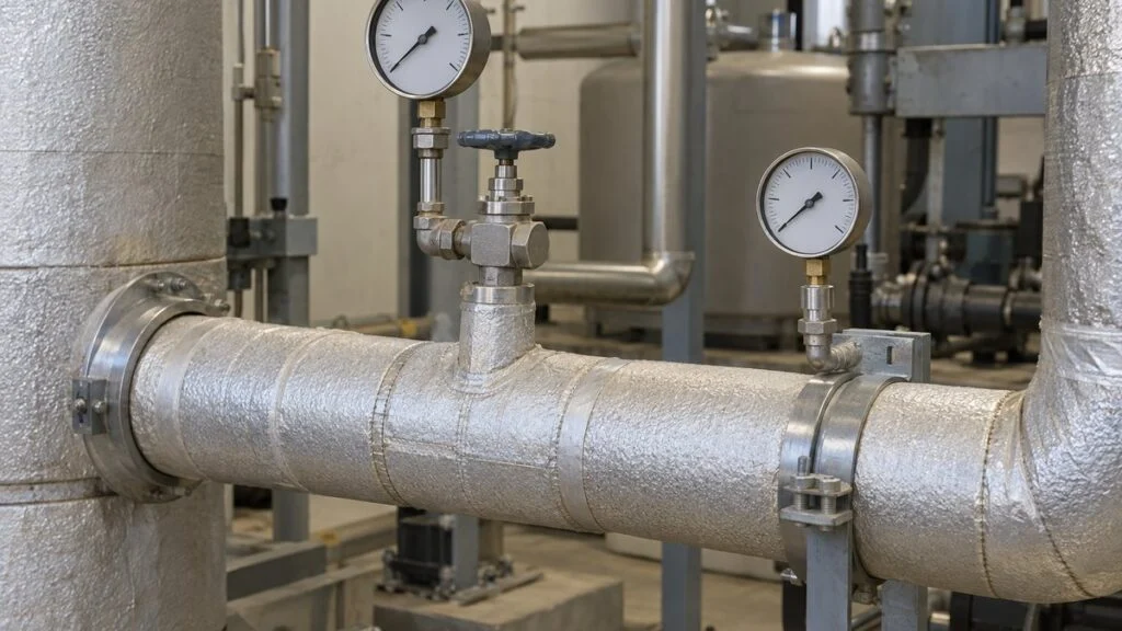
Make the valve numbers on the drawings match the tags on the equipment, and record what was done with removed protective covers and temporary parts. If the system changes after construction is complete, update the as-built drawings and the commissioning valve settings so the next round of troubleshooting goes faster.
Checklist Before You Call the Supplier
- Symptom defined: no flow at all, or flow but no heat
- Flow, supply and return temperatures, and suction and discharge pressures recorded at the same time
- Loop full: loop-side pressure, fill records, and any signs of leaks, drained water, or relief valve discharge
- Every valve on the series path traced on the diagram, including both sides of the pump and heat exchanger
- Branch valves, bypass, and balancing settings compared with the approved commissioning settings
- Pump rotation checked against the pump arrow and the manufacturer's viewing position (and VFD settings, if fitted)
- Speed or frequency setting compared with the design condition
- Construction records checked for caps, covers, blind plates, or tape that may remain; strainer differential pressure checked
- Air vented at the specified points; symptoms after venting recorded
- Gauge root valves open, gauge ranges and zero points checked, flow units matched
- Required flow and circuit pressure loss available from the design documents
Questions to Ask the Japanese Supplier or Contractor
If the design flow and pressure loss are not in the design documents, go back to the requirements in the purchase specification and confirm them with the supplier. Both the equipment's standalone rating and the performance the installed circuit needs have to line up. These questions help:
Related: Equipment Purchase Specification: Items, Checks, Template
- What are the design flow rate and the total circuit pressure loss at that flow? Which pump curve (model and speed) was used for selection?
- What are the required fill pressure and the minimum pressure at the highest point, and where does the expansion tank connect?
- What is the normal position of the makeup valve, and is the fill automatic or manual?
- Where are the specified air vent points, and what is the venting procedure for the pumps and equipment?
- Which viewing position defines the correct rotation direction, and how should direction be checked if the pump runs on a VFD?
- Were any protective caps, flange covers, blind plates, or protective tape used during construction, and do the records show they were removed?
- If the fluid is changed to an antifreeze mixture, how should the pump selection and circuit loss be rechecked?
Sample email (fictional details):
Subject: HW-01 hot water loop – low flow during commissioning
We are commissioning the HW-01 loop. Pump P-1 runs, but the loads on the third floor stay cold. Measured at 10:00: flow 4 m³/h against a design of 12 m³/h, suction 210 kPa(g), discharge 260 kPa(g). Air was vented at the specified points, all valves on the main path are open, and rotation matches the pump arrow. Could you please send (1) the design flow and circuit pressure loss, (2) the pump curve used for selection, (3) the required fill pressure and expansion tank connection point, and (4) the commissioning valve settings for the branch and bypass valves?
The tag numbers, readings, and design values above are fictional; replace them with your own.
Limits of This Guide
- It covers closed hot water circulation loops. Domestic hot water makeup piping and systems that transfer water to an open tank work differently.
- The calculations are illustrative, with fictional values. They are not design values or minimum pressure requirements for any system.
- Venting and opening flanges require shutdown, cooling, isolation, and residual-pressure checks under the site's procedures; wiring changes require power isolation and confirmation of no voltage. This guide lists what to check, not how to do that work.
- Valve positions, fill methods, and venting points vary by system and by company. The approved design and commissioning documents take priority.
FAQ
Does a closed makeup water valve always stop circulation?
No. If the loop could not be filled and air remains, it can. If the loop is already full and holding its water volume, it can still circulate. Check the loop-side pressure, the fill records, and any leaks or discharge rather than the makeup valve position alone.
If the building is 20 m tall, does the circulator need 20 m of head?
No. In a full, closed loop, the height is not added to the circulation head. Separate the static pressure that keeps the highest point full from the differential pressure needed to overcome circuit resistance at the required flow, and treat systems that pump to an open tank separately.
If the pressure gauge reads high, is water flowing?
Not necessarily. A closed valve or a blockage can create a pressure difference across the pump even with little flow. Read suction and discharge pressures, flow, and valve positions together; the discharge pressure alone does not confirm circulation.
Why does the gurgling come back after venting the air?
Air left from the first fill is only one cause. Also check for pressure drops, outside air drawn in, and gas coming out of the water as the temperature changes. Record the pressure, water temperature, and makeup and drain history when it happens, and trace why it repeats.
Will a bigger pump fix low flow in a hot water loop?
Not if the cause is air, a closed valve, a blockage, or a bypass short circuit. Confirm that the loop is full and the path is clear first, then compare the required flow and actual losses with the pump curve.
Sources
- Fill pressure, circulation losses, and air removal in closed heating systems: Grundfos, Circulator Handbook "Hydronic Heating Systems," pp. 40–41, 68–69
- Static pressure, pump differential pressure, and the risk of low pressure at high temperature: Grundfos, "Static pressure"
- Piping and air pockets, rotation direction, operating records, and inspection: Ebara, S-type pump instruction manual (Japanese); allowable values for individual models are not generalized here
- Head in closed circuits, circulation, and fluid properties: Caleffi, "Physical operating conditions in hydronic systems"
- Isolating air, flow, valve and control problems: Caleffi, "Troubleshooting process"
- Pump curves, system resistance, and operating point: Caleffi, "Physical concepts that aid troubleshooting"
- Input phase sequence and rotation direction on inverters: Mitsubishi Electric FA FAQ (Japanese)
- Checking residual voltage after power is cut: Mitsubishi Electric, FR-D700 catalog, safety precautions (Japanese); follow the manual for your equipment for waiting times and other precautions
Original article in JapaneseThis guide is adapted from a MONOSCOPE article written for readers in Japan: ループ配管で温水が流れない原因は?充水・エア抜き・弁とポンプの確認順序
About the editor
 MONOSCOPE EditorFOUNDER & EDITOR
Spent about ten years at a plant equipment maker and a plant engineering company, proposing, designing, and commissioning equipment, then moved into web marketing. Now a web consultant for B2B manufacturers, helping them explain their products and technology. Licensed in Japan as an Energy Manager and a Third-Class Chief Electrical Engineer.
Has run an engineering blog since 2017 (500+ articles) and a Japanese YouTube channel with about 20,000 subscribers. Each English guide is written from the Japanese shop-floor point of view and checked against the cited standards.