Thermocouple vs RTD: JIS/IEC Classes on Japanese Equipment
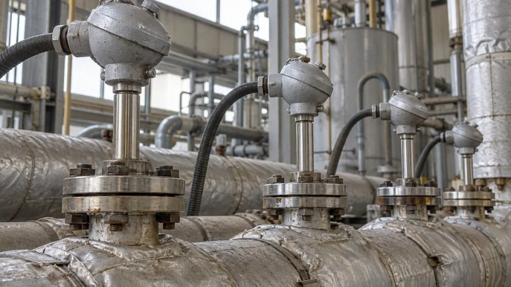
Picture a furnace line arriving from Japan (a fictional but typical case). The datasheet lists "K熱電対 クラス2" for the zone sensors and "Pt100 クラスA 3導線式" for the quench tank. The extension cable in the panel has a green jacket on some runs and a blue jacket on others, and the controller manual mentions both Pt100 and JPt100. Your local spares follow US color codes, where red marks the negative lead. Mixing these up rarely trips an alarm. The display simply shows a believable number that is several degrees off.
This guide explains how thermocouples and RTDs (resistance temperature detectors) differ, how the Japanese standards JIS C 1602, JIS C 1604, and JIS C 1610 relate to IEC 60584 and IEC 60751, and what to check on wiring before you replace a sensor or a cable on Japanese equipment. It ends with a checklist and a set of questions for the Japanese supplier.
- Principle: A thermocouple measures the voltage generated at the junction of two different metals. An RTD measures how the electrical resistance of platinum changes with temperature.
- Range: Thermocouples are for high temperatures (continuous limit up to 1,000°C [1,832°F] for Type K and 1,500°C [2,732°F] for Type B under JIS). JIS classes RTDs up to 600°C (1,112°F) at most, 500°C (932°F) for sheathed types.
- Accuracy: At 100°C, the tolerance is ±0.35°C for a Pt100 Class A element and ±2.5°C for a Type K Class 2 thermocouple.
- Wiring: Thermocouples need extension or compensating cable of the matching type, plus cold-junction compensation in the instrument. RTDs use ordinary copper cable, usually in a 3-wire connection.
- Selection: Check temperature range, accuracy, response, environment, protection tube, and the receiving instrument, in that order.
- Standards: JIS C 1602:2015 is a modified adoption of IEC 60584-1:2013, and JIS C 1604:2013 of IEC 60751:2008. Cable colors under current JIS follow IEC, but older Japanese installations and US wiring use different colors.
Contents
- Thermocouple vs. RTD: The Core Differences
- How JIS Maps to IEC (and What US Specs Use)
- Thermocouples on Japanese Specs
- RTDs on Japanese Specs
- Wiring: Compensating Cable Colors and 3-Wire RTDs
- How to Choose: Six Criteria
- Installation and Maintenance Points
- Where Thermistors and Infrared Thermometers Fit
- Checklist: Temperature Sensors on Japanese Equipment
- Limits of This Guide
- FAQ
- Sources
Thermocouple vs. RTD: The Core Differences
As a rule, choose a thermocouple for high temperatures, wide ranges, fast response, or heavy vibration, and choose an RTD when you need accuracy and stability up to a few hundred degrees Celsius. Panasonic's temperature controller FAQ draws the same line: RTDs for applications at relatively low temperatures (200°C or below) that need accuracy, and thermocouples for wide ranges, with some types able to measure above 1,000°C.
Everything else follows from the principle. A thermocouple produces a voltage (thermoelectric EMF), while an RTD presents a resistance. That difference, voltage versus resistance, decides what cable you can use and where errors creep in.
The different measuring principle affects range, accuracy, and wiring.
Response, vibration, and cable rows are general tendencies compiled by the editors from Chino, RKC, and Okazaki Manufacturing technical documents. Tolerances are standard values for new wire or elements and do not include cable or instrument error.
How JIS Maps to IEC (and What US Specs Use)
Japanese temperature sensor standards are based on IEC standards, but they are "MOD" (modified) adoptions, not word-for-word copies. The type letters, tolerance class structure, and Pt100 curve follow IEC, and each JIS lists its deviations from IEC in an annex (Annex JC in JIS C 1602 and JIS C 1604). Where a value is critical, check that annex.
| Subject | Japanese standard | IEC standard it is based on | Current IEC edition |
|---|---|---|---|
| Thermocouples (EMF tables, tolerance classes) | JIS C 1602:2015 | IEC 60584-1:2013 (MOD) | IEC 60584-1:2013 |
| Platinum RTDs (Pt100, classes AA–C) | JIS C 1604:2013 | IEC 60751:2008 (MOD) | IEC 60751:2022 (3rd edition) |
| Thermocouple extension and compensating cables | JIS C 1610:2012 | IEC 60584-3:2007 (MOD) | IEC 60584-3:2021 (3rd edition) |
Note the version gap for RTDs. IEC published the third edition of IEC 60751 in 2022, but JIS C 1604 remained the 2013 edition based on the 2008 IEC text when the Japanese source article checked in 2023. A Japanese Standards Association review document says the main change in the 2022 edition is a low-temperature water-immersion sealing test agreed between the parties, which is not used in Japan, and took the view that JIS did not need revising. A Japanese datasheet citing JIS C 1604:2013 is therefore normal and is not a sign of an outdated sensor.
Thermocouples on Japanese Specs
A thermocouple is two wires of different metals joined at one end. When the two junctions are at different temperatures, a voltage appears that depends on that difference (the Seebeck effect, discovered in 1821). According to Okazaki Manufacturing, this EMF depends only on the two materials and the temperatures at each end, not on wire diameter or length.
Measuring Junction, Reference Junction, and Cold-Junction Compensation
The junction at the measuring point is the measuring (hot) junction; the other end is the reference (cold) junction. A thermocouple only reports the temperature difference between the two, so you need to know the reference temperature to get the process temperature. JIS C 1602:2015 defines the reference EMF tables with the reference junction at 0°C.
Keeping a reference junction at 0°C is not practical on the shop floor. Industrial controllers and recorders measure the temperature at their own input terminals and add the matching voltage back electronically. This is cold-junction compensation (基準接点補償, kijun setten hosho).
Every wire between the sensor and the instrument counts as part of the thermocouple.
If ordinary copper wire replaces the compensating cable, the terminal head becomes a new reference junction and its temperature turns into error.
Thermocouple Types in JIS C 1602
JIS C 1602:2015 covers nine types: B, R, S, N, K, E, J, T, and Type C, which was added in the 2015 edition. B, R, and S are noble-metal (platinum-based) types. The others are base-metal types made with nickel, copper, or iron alloys. Type K is the most widely used industrial type.
Okazaki Manufacturing's instruction manual notes that Type K suits oxidizing and inert atmospheres but not reducing atmospheres or atmospheres containing sulfur, where its EMF can drop sharply in a short time. Pick the type with the atmosphere in mind, not only the temperature.
Choose by continuous limit (the temperature for continuous use in air) and by atmosphere.
Continuous and short-term limits: JIS C 1602:2015 Table 3 (bare wire in air). Atmosphere suitability: Okazaki Manufacturing manual TD-1001d. Characteristics: Hakko Electric technical documents. Protection tube and insulator materials can lower the usable temperature.
Continuous and Short-Term Limits Depend on Wire Size
JIS C 1602:2015 defines a continuous limit (常用限度, joyo gendo) for continuous use in air and a short-term overheat limit (過熱使用限度, kanetsu shiyo gendo) for brief use. Thinner wire means lower limits. For Type K, 0.65 mm wire has a continuous limit of 650°C and a short-term limit of 850°C; 3.20 mm wire has 1,000°C and 1,200°C.
A catalog line such as "Type K, −200 to 1,200°C" (an illustrative example, not a specific product) does not mean the sensor can run continuously across that range. Thin sheathed thermocouples degrade faster at high temperatures, so confirm the combination of operating temperature and wire diameter (or sheath OD) with the manufacturer.
Tolerance Classes 1, 2, and 3
Tolerance is the maximum allowed difference between the temperature converted from the standard EMF table and the actual temperature. JIS C 1602:2015 uses Classes 1 to 3, the same structure as IEC 60584-1. For Type K (|t| is the absolute value of the measured temperature):
- Class 1: ±1.5°C from −40°C to below 375°C; ±0.004·|t| from 375°C to below 1,000°C
- Class 2: ±2.5°C from −40°C to below 333°C; ±0.0075·|t| from 333°C to below 1,200°C
- Class 3: ±2.5°C from −167°C to below 40°C; ±0.015·|t| from −200°C to below −167°C
US specs use a different vocabulary. Under ASTM E230, Type K "standard limits" are ±2.2°C or ±0.75%, and "special limits" are ±1.1°C or ±0.4%, whichever is greater, over 0 to 1,260°C. These are close to JIS/IEC Class 2 and Class 1 but not identical, so do not treat "Class 1" and "special limits" as interchangeable on a purchase order.
The standard states that these tolerances apply only to new wire. Thermocouple wire changes with use at high temperature and its EMF drifts, so in-service accuracy has to be confirmed by periodic checks.
RTDs on Japanese Specs
An RTD uses the fact that a metal's electrical resistance rises with temperature. Platinum is the most widely used RTD material in industry because it covers a wide range and has a large temperature coefficient. The instrument passes a small current through the element, measures the resistance, and converts it to temperature.
Pt100, Pt1000, and the Old JPt100
JIS C 1604:2013 defines Pt100, Pt500, and Pt1000, with nominal resistances of 100 Ω, 500 Ω, and 1,000 Ω at 0°C. All have a resistance ratio R100/R0 of 1.3851, consistent with IEC 60751.
Watch for JPt100, an older Japan-only curve with a ratio of 1.3916. When JIS adopted the IEC-aligned Pt100 in 1989, the old curve was kept as "JPt100." It was removed from JIS in the 1997 revision (M-System, Keyence).
JPt100 is not in the current JIS C 1604:2013, but Okazaki Manufacturing notes that it is still used in some places, and some PLC temperature input modules let you select either Pt100 or JPt100. When you replace a sensor or an input card on older Japanese equipment, check that the sensor and the input setting match.
The size of the mismatch: at 100°C a Pt100 reads 138.51 Ω and a JPt100 reads 139.16 Ω, a 0.65 Ω difference. Pt100 sensitivity near 100°C is about 0.38 Ω per °C, so a mismatched setting shifts the reading by roughly 1.7°C at around 100°C (an estimate calculated from the resistance ratios).
Tolerance Classes AA, A, B, and C
JIS C 1604:2013 (based on IEC 60751:2008) divides RTD tolerance into four classes. Each class also has a validity range that differs between wire-wound and thin-film elements.
- Class AA: ±(0.1°C + 0.0017|t|); wire-wound −50 to 250°C, thin-film 0 to 150°C
- Class A: ±(0.15°C + 0.002|t|); wire-wound −100 to 450°C, thin-film −30 to 300°C
- Class B: ±(0.3°C + 0.005|t|); wire-wound −196 to 600°C, thin-film −50 to 500°C
- Class C: ±(0.6°C + 0.01|t|); wire-wound −196 to 600°C, thin-film −50 to 600°C
JIS also states that Classes AA and A do not apply to 2-wire RTDs. A Class A element wired in 2-wire cannot claim Class A accuracy.
On standard tolerance alone, RTDs win up to a few hundred degrees.
Calculated from JIS C 1602:2015 Table 2 and JIS C 1604:2013 Tables 3 and 4. Values are for a new sensor alone and exclude extension cable, lead resistance, instrument error, and drift over time.
Self-Heating and Measuring Current
Because the instrument passes current through the element, the element warms itself slightly. This is self-heating. JIS C 1604:2013 sets typical measuring currents of 0.5 mA, 1 mA, and 2 mA, and limits the maximum measuring current to a value at which self-heating stays within 25% of the tolerance.
Okazaki Manufacturing's manual notes that its accuracy guarantee applies only at the specified measuring current; a different current can add self-heating error. If you replace the controller or the input module, check that its measuring current matches the sensor specification.
Wiring: Compensating Cable Colors and 3-Wire RTDs
Thermocouples and RTDs need completely different cable. Wiring mistakes are common in the field and hard to spot, because the display still shows a plausible value.
Thermocouple Cable Colors: JIS, IEC, and US
A thermocouple must be extended with extension or compensating cable (補償導線, hosho dosen) whose EMF characteristics nearly match the thermocouple. Under JIS C 1610:2012, the colors follow IEC 60584-3: the positive conductor and the sheath carry the type color, and the negative conductor is white. US practice under ANSI/ASTM is different: the negative conductor is red.
| Type | Current JIS C 1610 / IEC 60584-3 (+ / − / sheath) | ANSI/ASTM extension grade, US (+ / − / jacket) | Older Japanese sheath color (JCS 4365 "Category 2") |
|---|---|---|---|
| K | Green / White / Green | Yellow / Red / Yellow | Blue |
| J | Black / White / Black | White / Red / Black | Yellow |
| T | Brown / White / Brown | Blue / Red / Blue | Brown |
| E | Violet / White / Violet | Purple / Red / Purple | Purple |
| N | Pink / White / Pink | Orange / Red / Orange | — |
| R, S | Orange / White / Orange | — | Black |
The Japanese cable industry standard JCS 4365:2022 still lists two sheath color schemes side by side: one matching the current JIS/IEC colors (Category 1, green for Type K) and one carrying over the older Japanese colors (Category 2, blue for Type K). So a blue cable on a Japanese machine may well be Type K, and a green one is also Type K. On a US crew, blue usually means Type T. Identify cable by the marking printed on the sheath and the drawing, not by color alone.
A few more points from JIS C 1610 and Okazaki Manufacturing:
- Compensating cable for intrinsically safe circuits has a blue outer sheath regardless of type under JIS. This is another reason not to read blue as a type color.
- Cable has its own tolerance. Type KX Class 2 cable is ±100 µV, about ±2.5°C when the measuring junction is at 900°C.
- Using the wrong cable type or reversing + and − causes large errors. Keep the connection between thermocouple and cable at 80°C (176°F) or below.
RTDs: 2-Wire, 3-Wire, and 4-Wire
An RTD is read as a resistance, so the resistance of the leads becomes error. JIS C 1604:2013 defines 2-wire, 3-wire, and 4-wire connections. No special cable is needed; ordinary instrument or control cable works.
They differ in how much lead resistance they cancel. 3-wire is the industrial norm.
Based on JIS C 1604:2013 clauses 11.2 and 11.3, Okazaki Manufacturing manual TD-1001d, and Keyence "RTD basics."
Worked Examples: How Big Are Wiring Errors?
The two fictional examples below use JIS reference values to show the size of typical wiring errors. Both are simplified; real errors depend on the instrument and the installation.
Missing cold-junction compensation or uncancelled lead resistance changes the reading noticeably.
Fictional examples by the editors. Example 2 sensitivity: dR/dt = R0(A + 2Bt), A = 3.9083 × 10⁻³, B = −5.775 × 10⁻⁷, t = 50°C. Check actual lead resistance from the cable specification and length.
Example 1 also explains what happens when copper wire replaces compensating cable. The terminal box where the copper starts becomes a new reference junction, and nothing compensates for the difference between that box and the instrument. If the box temperature changes between summer and winter, the error changes with the seasons.
Some installations avoid long thermocouple or RTD runs by converting the signal to 4–20 mA near the sensor. If the Japanese panel receives a transmitter signal instead, see 4-20 mA vs 1-5 V: Why Japanese Panels Use 250 Ω Inputs. For how each point appears on the I/O list, see DI/DO, AI/AO, PI/PO Meaning: Reading a Japanese I/O List.
How to Choose: Six Criteria
Narrow down the sensor in the order below, then check the result against the input specification of the instrument that will read it.
Start with the conditions that decide the sensor type, then move to construction and wiring.
General tendencies compiled by the editors. Confirm the final selection with the manufacturer's selection guide and the instrument manual.
Temperature Range and Accuracy
Temperature range comes first. Under JIS C 1604:2013, even high-temperature RTDs stop at 600°C (500°C for sheathed types), so hardening furnaces, melting furnaces, and other locations well above a few hundred degrees need thermocouples.
From ambient up to a few hundred degrees, both work. The deciding question is whether quality requires accuracy better than ±1°C. As Figure 4 shows, at 100°C a Pt100 Class A is ±0.35°C and a Type K Class 2 is ±2.5°C, several times apart on standard tolerance alone.
Response Speed and Environment
Response speed depends mostly on the sensor's heat capacity. Chino's technical documents list fast response as a thermocouple strength. According to Okazaki Manufacturing, an exposed measuring junction gives the fastest response among sheathed thermocouples, but the bare wire needs careful handling.
For vibration, RKC's product literature says sheathed thermocouples resist vibration and shock well, and sheathed RTDs are more robust than standard RTDs. Near pumps, compressors, or conveyors, check first whether the sensor is sheathed; that matters more than thermocouple vs. RTD.
Protection Tube Material
The protection tube (保護管, hogo-kan) shields the sensor from the process and atmosphere. Chino's technical documents list measuring temperature, pressure, corrosion, gas-tightness, thermal shock, mechanical shock, and response speed as selection factors. Japanese specs use JIS material names such as SUS304, which is comparable to AISI 304.
Choose by resistance to sulfur, reducing gases, and other atmospheres, not by temperature alone.
Values from Chino's "Protection Tubes" technical document. Actual life varies widely with atmosphere, temperature cycling, and flow velocity. Okazaki Manufacturing warns against inserting platinum thermocouples (R, S, B) directly into metal protection tubes.
Cable Length and Controller or PLC Input
Finally, check the receiving instrument. Each controller or PLC temperature input supports specific sensor types. Mitsubishi Electric's MELSEC iQ-F temperature inputs, for example, list thermocouple Types K, J, T, B, R, and S (some models also E and N). For RTDs, they support Pt100, and the FX5-4LC temperature control module also accepts 3-wire JPt100 and 2-wire or 3-wire Pt1000.
For long runs, Keyence advises checking the cable's resistance per meter and choosing cable within the instrument's allowable signal source resistance. For thermocouples, also check the cable tolerance and its insulation temperature rating; for RTDs, check the allowable lead resistance in the instrument manual.
Installation and Maintenance Points
Correct selection is not enough. Most error comes from installation and aging rather than the sensor itself. The points below come from Okazaki Manufacturing's instruction manual.
- Insertion length: If the tube is not inserted deeply enough, heat conducted along it from the surroundings causes error. Okazaki's guideline is at least 5 times the tube OD in liquids and at least 10 times in gases, plus the element length for RTDs, since the element sits at the tip.
- Insulation resistance: Low insulation resistance causes reading errors and induced noise. Okazaki's replacement guideline at inspection is 1 MΩ or below.
- Tube condition: Soot and sludge on the protection tube slow heat transfer. Remove them while checking for wall thinning and damage.
- Thermocouple drift: Thermocouple wire becomes inhomogeneous with use. Type K shows a reversible EMF increase in the 250–600°C range (short-range ordering). Be careful when changing insertion depth or calibrating a used sensor; compare under the same conditions as installed.
To check in-service accuracy, compare against a calibrated thermometer, either by swapping in a calibrated sensor or by inserting one right next to it. Both methods need a stable process temperature and matching insertion depth. In Japan, calibration traceable to national standards comes from laboratories registered under JCSS (Japan Calibration Service System), which has a "temperature" category covering contact thermometers. Under the JCSS guideline published by NITE, designated secondary standards for thermocouples are calibrated by the National Institute of Advanced Industrial Science and Technology (AIST) against designated primary standards. See JCSS Calibration: Certificates, Intervals, and Records.
In hazardous areas in Japan, such as refineries and chemical plants, temperature sensors fall under the explosion-protection construction standard for electrical equipment (Ministry of Labour Notification No. 16 of 1969), and Okazaki Manufacturing lists flameproof and intrinsically safe as the two protection types used for temperature sensors. Intrinsically safe systems place a barrier in the non-hazardous area to limit the energy that can reach the hazardous area. Chino's intrinsically safe thermocouples, for example, are certified as a combination with a Zener barrier or an isolation barrier. Barrier selection and installation must be checked by qualified personnel and the manufacturer of the certified product, and work near hot parts or live circuits must follow your site's safety rules. For Japanese explosion-proof markings, see Ex d vs Ex e: Japanese Explosion-Proof Marks and TIIS.
Where Thermistors and Infrared Thermometers Fit
Thermistors are sintered semiconductor ceramics made from oxides of metals such as nickel, manganese, and cobalt; NTC types drop in resistance as temperature rises (Panasonic). According to Okazaki Manufacturing, they change resistance sharply per degree but cannot cover wide ranges, so they are used mainly inside equipment rather than as process sensors.
Infrared (radiation) thermometers measure temperature without contact from the infrared energy an object emits. Keyence notes they suit moving objects or objects whose temperature would change on contact, but the emissivity setting, which depends on material and surface, directly affects accuracy, and they cannot measure internal or gas temperatures. Fluid in a pipe or a furnace atmosphere remains thermocouple and RTD territory.
Checklist: Temperature Sensors on Japanese Equipment
Use this before replacing a sensor, cable, or input module, or when reviewing a Japanese datasheet.
- Sensor type on the datasheet: 熱電対 (netsudentsui, thermocouple) or 測温抵抗体 (sokuon teikotai, RTD)
- Thermocouple type letter (K, J, T, E, N, R, S, B) and tolerance class (クラス1/2/3)
- RTD curve: Pt100, Pt1000, or JPt100, and the matching setting on the controller or PLC input
- RTD class (AA, A, B, C), element type (wire-wound or thin-film), and the temperature range where that class applies
- RTD wiring: 2導線式, 3導線式, or 4導線式 (2-, 3-, or 4-wire); Class A or better must not be 2-wire
- Compensating cable: type marking on the sheath, color scheme (current JIS/IEC, older JIS, or ANSI), and polarity at both ends
- Wire or sheath diameter vs. continuous limit at your operating temperature
- Protection tube material and insertion length vs. the atmosphere and process
- Measuring current of the instrument vs. the RTD specification
- Hazardous-area classification and whether the sensor and barrier are certified for the location
Questions for the Japanese Supplier
- Which standard and edition is the sensor made to: JIS C 1602:2015, JIS C 1604:2013, or IEC?
- Is this RTD Pt100 or JPt100, and how is the controller input configured?
- Which color scheme does the installed compensating cable follow, and which conductor is positive?
- What is the continuous operating limit for this sheath diameter at our process temperature?
- Can you supply a replacement with ANSI/ASTM color-coded cable, or should we keep the JIS/IEC colors for this machine?
Sample inquiry email:
Subject: Temperature sensor specification for [machine name / serial no.]
We are preparing spares for the temperature sensors on this machine. Could you confirm the following for each tag number on the attached list: (1) sensor type and class (for example, Type K Class 2, or Pt100 Class A), (2) for RTDs, whether the curve is Pt100 or JPt100 and whether the wiring is 3-wire or 4-wire, (3) the type and color code of the compensating cable used, and (4) the sheath diameter and protection tube material. Please also let us know if any part of the input setting on the controller depends on these choices.
Limits of This Guide
- Values are from JIS standards and Japanese manufacturers' documents as cited. IEC, ASTM, and supplier-specific values may differ in range or wording.
- The older-JIS color column lists sheath colors from JCS 4365:2022 only. Conductor colors on older cable vary, so confirm them with the supplier.
- Tolerances are for new sensors. Installed accuracy includes cable, instrument, installation, and drift.
- Protection tube temperatures are guideline values from one manufacturer (Chino); actual life varies with atmosphere, temperature cycling, and flow velocity.
- Hazardous-area requirements depend on the country of installation. Japanese certification does not automatically satisfy local rules.
FAQ
Can I extend a thermocouple with ordinary copper wire?
No. Use the extension or compensating cable specified for that thermocouple type. With copper wire, the terminal box becomes a new reference junction, and the reading shifts by the temperature difference between that box and the instrument.
What is the difference between Pt100 and JPt100?
JPt100 is an older Japan-only RTD curve. Its R100/R0 ratio is 1.3916, versus 1.3851 for Pt100 under IEC 60751 and JIS C 1604. A mismatch between sensor and input setting shifts the reading by about 1.7°C near 100°C.
Is JIS C 1604 the same as IEC 60751?
It is close but not identical. JIS C 1604:2013 is a modified adoption of IEC 60751:2008, with the same Pt100 curve and Class AA to C structure. IEC has since issued a 2022 edition, which JIS has not adopted.
Why is the Type K cable on my Japanese machine blue?
It probably follows the older Japanese color scheme, in which Type K cable has a blue sheath. Current JIS and IEC use green. Intrinsically safe compensating cable is also blue under JIS. Check the sheath marking before assuming a type.
Should I choose 2-wire, 3-wire, or 4-wire for an RTD?
3-wire is the industrial standard because it cancels lead resistance. 2-wire is limited to short runs, and 4-wire is used for high-accuracy or reference measurement.
Sources
- JIS C 1602:2015 Thermocouples (IEC 60584-1:2013 MOD): standard text, Table 2 (tolerances), Table 3 (continuous and short-term limits), Annex A (Type K reference EMF) (Japanese)
- JIS C 1604:2013 Platinum resistance thermometers (IEC 60751:2008 MOD): standard text and Tables 1–6 (Japanese)
- JIS C 1610:2012 Extension and compensating cables for thermocouples (IEC 60584-3:2007 MOD): Table 2 (tolerances), Table 9 (colors) (Japanese)
- JCS 4365:2022 Thermocouple extension and compensating cables, Table 6 and corrigendum of April 28, 2026, Japanese Electric Wire & Cable Makers' Association (Japanese)
- IEC 60751:2022 and IEC 60584-3:2021, IEC Webstore
- Japanese Standards Association: JIS review documents on JIS C 1604 and IEC 60751:2022 (Japanese)
- Thermometrics Corporation: Thermocouple color code reference (ANSI/ASTM)
- Pelican Wire: Thermocouple tolerances (ASTM E230)
- Okazaki Manufacturing: Temperature sensor instruction manual TD-1001d; thermocouple and RTD principles (Japanese)
- Chino: Temperature sensor guide, protection tubes, intrinsically safe thermocouples (Japanese)
- Keyence: Thermocouple basics, RTD basics, infrared temperature sensor basics (Japanese)
- Panasonic: Temperature controller FAQ on sensor selection; NTC thermistor basics (Japanese)
- M-System: "JIS standards for platinum RTDs" (Japanese)
- RKC: General-purpose temperature sensors (Japanese)
- Hakko Electric: Thermocouple types and characteristics (Japanese)
- Mitsubishi Electric: MELSEC iQ-F temperature sensor input
- NITE: JCSS technical requirements guideline for contact thermometers (thermocouples), 15th edition (Japanese)
Original article in JapaneseThis guide is adapted from a MONOSCOPE article written for readers in Japan: 熱電対と測温抵抗体の違い|温度範囲・精度クラス・配線(補償導線・3線式)と選び方
About the editor
 MONOSCOPE EditorFOUNDER & EDITOR
Spent about ten years at a plant equipment maker and a plant engineering company, proposing, designing, and commissioning equipment, then moved into web marketing. Now a web consultant for B2B manufacturers, helping them explain their products and technology. Licensed in Japan as an Energy Manager and a Third-Class Chief Electrical Engineer.
Has run an engineering blog since 2017 (500+ articles) and a Japanese YouTube channel with about 20,000 subscribers. Each English guide is written from the Japanese shop-floor point of view and checked against the cited standards.