4-20 mA vs 1-5 V: Why Japanese Panels Use 250 Ω Inputs
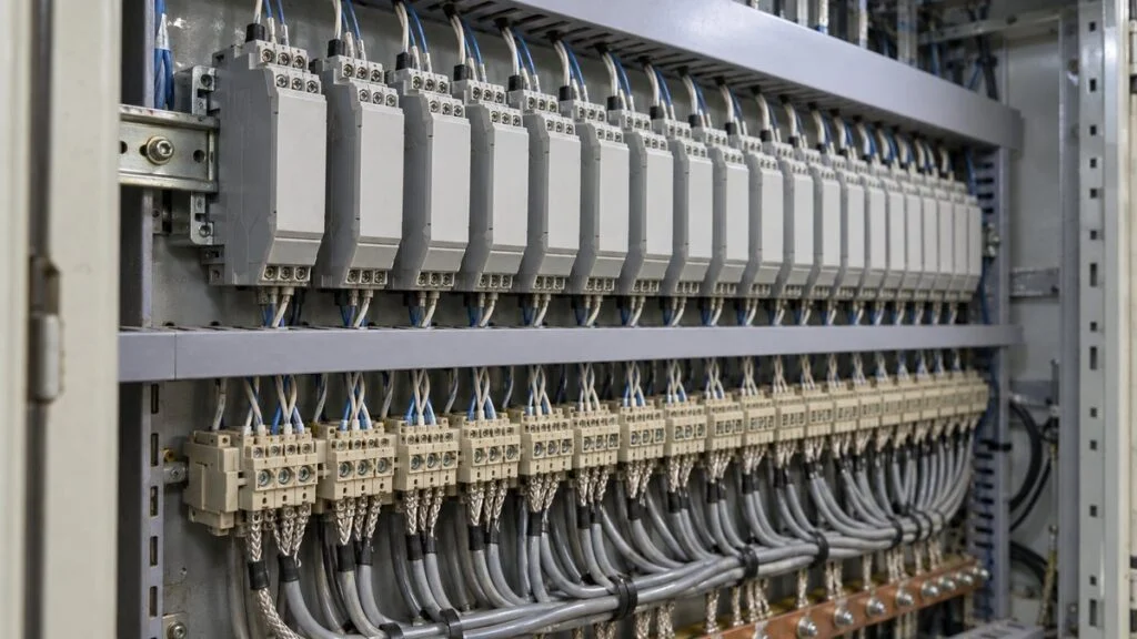
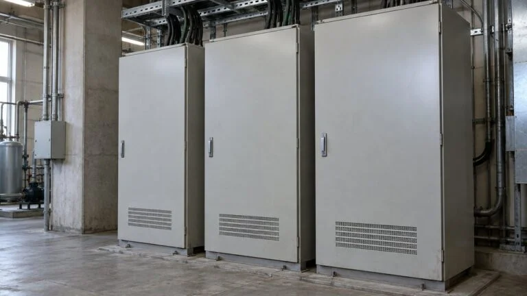
You open the I/O list for a panel built in Japan. Your DCS cards expect 4–20 mA, but half of the analog inputs on the list say "DC1-5V." There is a 250 Ω resistor on the terminal drawing that nobody on your side ordered, and the transmitter loop shows a box labeled "distributor." Is this a different signal standard, and will it work with your system?
The short answer: in most cases it is the same signal, seen at two different points. The field transmitter sends 4–20 mA. Somewhere in the panel, a 250 Ω resistor turns that current into 1–5 V, because 4 mA × 250 Ω = 1 V and 20 mA × 250 Ω = 5 V. Japanese panels often distribute the signal internally as 1–5 V, which is why "DC1-5V" points show up on their I/O lists. What you have to pin down is where the conversion happens, who supplies the resistor and the loop power, and what each receiver actually expects.
This guide covers why the field side uses current, why Japanese panels often switch to voltage, how 2-wire and 4-wire loops differ, how technicians typically check a live loop, and a checklist and question list for reviewing a Japanese supplier's signal specification.
Contents
4–20 mA in One Minute
4–20 mA is an analog instrument signal that carries 0–100% of a measuring range as a DC current: 0% is 4 mA, 100% is 20 mA, and values in between scale linearly. Older control systems used other ranges, and some 10–50 mA loops are still in service. Today, IEC 60381-1 defines DC current signals for process control, and 4–20 mA is the range most plants use. A panel or DCS receives it on an AI (analog input) and sends it on an AO (analog output); the guide to DI/DO, AI/AO, and PI/PO on Japanese I/O lists explains those labels.
Temperature sensors such as thermocouples and resistance temperature detectors (RTDs) usually feed a transmitter that converts their signal to 4–20 mA. Take a temperature transmitter ranged 0–200°C. The figure below lines up current, percent of range, the voltage across a 250 Ω resistor, and temperature.
The 16 mA span covers 0–100%. Passed through a 250 Ω resistor, the same current becomes 1–5 V.
Voltages assume a 250 Ω receiving resistor.
To turn any reading back into the process value, use this formula:
The same 4–20 mA signal carries readings from temperature, pressure, level, and flow transmitters, and it also sends commands out to the field: the valve position command to a control valve's positioner, or the speed command to a variable frequency drive (VFD). Mitsubishi Electric's general-purpose inverters, for example, accept 4–20 mA as an analog speed command alongside 0–5 V and 0–10 V. In short, 4–20 mA shows up wherever a value changes continuously and the control action is proportional.
Related: Electro-Pneumatic vs. Pneumatic Positioners: How They Work
Why the Field Side Uses Current
A Live Zero Shows a Broken Wire
Because 0% is 4 mA rather than 0 mA, a reading near 0 mA suggests a broken wire rather than a real measurement, so the receiver can tell a true zero from an open circuit. The 4 mA floor was chosen to cover an instrument's own operating current plus a margin. That matters most for 2-wire transmitters, which take their operating power from the same two signal wires. Their electronics are designed to run on less than 4 mA, so the transmitter keeps working even when the process sits at 0%.
Currents outside 4–20 mA can also signal a fault. NAMUR, a German association of process-automation users, recommends the ranges below in NE 43.
3.8–20.5 mA counts as a measurement; currents outside that band signal a fault.
Settings vary by transmitter. On Yokogawa's EJX430S pressure transmitter, the default normal output range is 3.6–21.6 mA, 3.8–20.5 mA with option /C2, and the burnout output is 22.4 mA (high) or 3.2 mA (low). Set the receiver's alarms to match the transmitter.
Current Does Not Drop Over Distance
In a series loop, the same current flows through every part of the circuit, so a long cable does not reduce it. A voltage signal sent over the same cable loses some of its value to wire resistance, and the receiver reads low. That is why long runs from the field to the panel use current.
How far can a loop reach? Distance itself is not the limit. What matters is whether the total loop resistance stays within the transmitter's allowable load. The figure works through one example with a 2-wire pressure transmitter.
Find the allowable load from the supply voltage, subtract the receiver, and the rest is available for the cable.
Conditions: Yokogawa EJX430S (display/interface code E or N, general-use type), 24 V supply, one 250 Ω receiver, CVV 1.25 mm² control cable (maximum conductor resistance at 20°C)
This is a resistance-only upper limit, not a typical reach. Electrical noise along the route, supply-voltage variation, the number of receivers, other devices in the loop, and HART communication (which has its own minimum-voltage requirement) all shorten it. Conductor resistance also rises with temperature.
Under these conditions the arithmetic allows about 10 km, but change the transmitter, power supply, or cable and the answer changes. Before extending a loop, compare three values on the datasheets: supply voltage, receiver resistance, and cable size. CVV is the Japanese designation for a PVC-insulated, PVC-sheathed control cable.
Why Japanese Panels Switch to 1–5 V
Current suits the long run from the field. Inside the panel, though, the same signal often needs to reach several devices: a controller, a recorder, an indicator, the DCS. Japanese instrument suppliers call 4–20 mA DC and 1–5 V DC toitsu shingo (統一信号, "unified signals"), and their signal conditioners and receivers commonly accept either one. Yokogawa's JUXTA M series, for example, is described as signal conditioners for unified signals with an I/O range of 4–20 mA DC or 1–5 V DC.
The conversion takes only a resistor. By Ohm's law, V = R × I:
Japanese drawings call this resistor the jushin teiko (受信抵抗, "receiving resistor"). It may be a discrete resistor on a terminal block, or it may sit inside the receiving device. PLC analog input modules read current the same way: Mitsubishi Electric's R60AD4 has a 250 Ω input resistance on its current input.
For 2-wire transmitters, Japanese panels typically use a distributor (ディストリビュータ, also called a 2-wire transmitter power supply or converter). It sends 24 V to the transmitter, receives the returning 4–20 mA across 250 Ω, and outputs 1–5 V or another signal. The typical result is 4–20 mA from the field to the panel, then 1–5 V inside the panel.
The reason is wiring topology. To share one 4–20 mA signal, every receiver has to sit in series in the loop, so a single open connection stops all of them. In a series loop, each 250 Ω receiver also adds to the loop load: two of them total 500 Ω, which still fits the 587 Ω limit in Figure 3 but leaves only 87 Ω for the cable. A 1–5 V signal can be wired in parallel to high-impedance inputs (the R60AD4's voltage input, for comparison, is 1 MΩ), and losing one receiver does not affect the others. Where the signal has to stay as current, a signal isolator with multiple outputs can split one 4–20 mA signal into separate loops.
Current from the field to the panel, voltage for distribution inside the panel: that is the usual combination.
1–5 V also has a live zero (0% = 1 V), so a broken wire shows up as 0 V.
The reverse conversion is not symmetrical. Turning 1–5 V into 4–20 mA requires an active device, such as a signal converter or isolator, that has its own power and can drive current into a loop. A resistor alone cannot do it. If a Japanese panel outputs 1–5 V and your system expects 4–20 mA, someone has to add that converter.
2-Wire vs. 4-Wire Loops
Loops are classified by where the transmitter gets its power. Japanese documents write these as 2-sen-shiki (2線式, 2-wire) and 4-sen-shiki (4線式, 4-wire).
In a 2-wire loop the signal wires also carry power; a 4-wire device has separate power wires.
2-wire (loop-powered)
4-wire (separately powered)
3-wire devices (power negative and signal negative shared) also exist. Check the wiring diagram in each device's specifications.
Common wiring mistakes are omitting loop power or powering the same loop from two sources. A 2-wire transmitter connected straight to an analog input that supplies no power will not produce any current. Feeding 24 V from the panel into a 4-wire device that already powers its own output puts two sources in the loop, and the reading will be wrong. Marking each line on the signal list as "2-wire (powered from panel)" or "4-wire (self-powered)" prevents both errors. When the panel is Japanese and the field devices are local, or the other way round, this is one of the first things to confirm.
Analog signals can pick up noise from nearby cables. The noise appears as measurement error, and in a control loop it can affect control of the actual process. Shielded twisted-pair cable is the usual choice, with the shield typically grounded at one end. Field cables are often gathered in a junction box and run to the panel as a multicore cable; see JB (junction box) on Japanese electrical drawings.
Related: Cable Shield Grounding: One End vs Both Ends, Japan Specs
How Technicians Check a 4–20 mA Loop
Measuring current is harder than measuring voltage: a meter in parallel reads nothing useful, so the loop either has to be opened or read some other way. Field technicians generally use one of three approaches. Which one is allowed, and how it is done, follows your site's work procedures and the instrument and meter manuals; the overview below is for orientation only.
The choice depends on whether the loop can be opened, whether there is a receiving resistor, and what tools are on hand.
The reading example assumes a 250 Ω receiving resistor. Confirm the actual value in the receiver's specifications.
- Meter in series. The meter must be in series with the loop, so one wire is lifted from the terminal and the meter is placed in the gap. The moment the wire comes off, the receiver sees 0 mA, which can trip alarms or drive the control loop. Sites therefore coordinate with the control room and put the affected control in manual first. If the reading stays at 0 mA, the usual suspects are the meter range, a lead in the wrong jack, or, on a 2-wire loop, missing loop power from the panel.
- Voltage across the receiving resistor. Where the loop has a 250 Ω receiver, the voltage across it gives the current without opening anything: 3.0 V means 12 mA and 1.0 V means 4 mA. This is the 1–5 V side of the same signal. If the resistor is not 250 Ω, divide by its actual value.
- Clamp meter. A clamp reads the magnetic field around a conductor, so no wire has to be removed. Clamping both the positive and negative wires cancels the fields and reads zero, so only one is clamped. Reading 4–20 mA calls for a process clamp with fine mA resolution; the Fluke 771, for example, reads 0–20.99 mA in 0.01 mA steps and fits conductors up to 4.5 mm in diameter. Fields from nearby cables affect such small currents, so the clamp is zeroed before use.
Before measuring instruments in hazardous (explosion-protected) areas, confirm the required work authorization and which test instruments may be brought in. Japan uses its own certification marks for these areas; see Ex d vs. Ex e and Japanese explosion-proof marks.
To check the receiving side, a current source injects a known value: 4 mA should read 0% and 20 mA should read 100%, and stepping the signal while watching a valve or pump speed confirms the wiring. Loop calibrators combine measuring and sourcing in one tool. The Fluke 715, for example, sources 0–24 mA and can measure current while supplying 24 V loop power. They work in two modes: source, where the calibrator drives current into a receiver or valve by itself, and simulate, where it takes the place of a 2-wire transmitter in a loop powered by the panel, so the wiring and receiver can be checked together.
Checklist: Reading a Japanese Analog Signal Spec
Use this when reviewing a Japanese supplier's I/O list, signal list, or instrument specification for interfaces with your system. The Japanese terms are what you are likely to see on the documents.
| Item | What you may see | What to confirm |
|---|---|---|
| Signal type at each interface point | DC4-20mA, DC1-5V, DC0-10V | Whether the value is the field signal or the in-panel signal after conversion |
| Loop power | 2線式 (2-wire), 4線式 (4-wire), 電源供給 (power supply) | Which side supplies 24 V; no loop powered twice or not at all |
| Receiving resistor | 受信抵抗 250Ω (jushin teiko) | Where it is installed, who supplies it, and whether your receiver already has one |
| Distributor / converter | ディストリビュータ (distributor), 変換器 (henkanki, converter), アイソレータ (isolator) | Model, output signal, isolation, and who supplies and wires it |
| Receivers in series | Loop or wiring diagram | Total receiver resistance vs. the transmitter's allowable load |
| Fault signaling | Burnout, NE43, 断線検出 (open-wire detection) | Transmitter output range and burnout direction; receiver alarm thresholds to match |
| HART | HART通信 | Whether HART is used and whether the loop meets the transmitter's load and voltage limits for communication |
| Cable | CVV, CVV-S (shielded), mm² size | Conductor size, shield, and which end is grounded |
| Direction | AI / AO, 入力 / 出力 | Which panel the list is written from |
Questions to Ask the Japanese Supplier
- At each interface terminal, is the signal 4–20 mA or 1–5 V?
- Is each transmitter 2-wire or 4-wire, and which side provides loop power?
- Where is the 250 Ω receiving resistor, and is it in your scope of supply?
- Does any loop have more than one receiver in series? What is the total load?
- What are the transmitters' burnout settings, and what alarm thresholds do you expect on the receiving side?
- Is HART used on any loop?
- Which end of the cable shield is grounded?
A short inquiry you can adapt:
Subject: Analog signal interface – confirmation of 1–5 V / 4–20 mA points
Hello [Name],
We are reviewing the I/O list [document no., revision]. Our DCS analog inputs accept 4–20 mA with internal receiving resistors. Several points on your list are marked DC1-5V. Could you confirm, for each of these points:
1. Whether the signal at the interface terminal is 4–20 mA or 1–5 V
2. Whether the transmitter is 2-wire or 4-wire, and which side supplies loop power
3. Where the 250 Ω receiving resistor or distributor is installed, and whether it is in your scope
4. The transmitter burnout setting (high or low)
Thank you,
[Your name]
Limits of This Guide
- The 250 Ω and 1–5 V figures describe a common arrangement, not a rule. Receiving resistors, input ranges, and loop power vary by product, company, and project; the supplier's documents decide.
- The loop-distance figure is one worked example under stated conditions, not a general reach.
- The measurement section describes common approaches. It is not a work instruction: who may open a loop, what permits apply, and which meters are allowed follow your site's procedures, especially in hazardous areas.
- Fault-current ranges follow NAMUR NE 43 and one transmitter's datasheet; your instruments may be set differently.
FAQ
Can I Convert 1–5 V Back to 4–20 mA?
Yes, but not with a resistor. You need an active device, such as a signal converter or isolator, that generates current from the voltage. 4–20 mA to 1–5 V needs only a 250 Ω resistor; the reverse needs a power source and a circuit that can drive current into the loop.
What Is the Difference Between 0–20 mA and 4–20 mA?
0–20 mA puts 0% at 0 mA, so a zero reading and a broken wire look the same. PLC analog input modules often offer a 0–20 mA range, but process instrumentation mostly uses 4–20 mA because it reveals open circuits.
How Does HART Relate to 4–20 mA?
HART superimposes a digital signal on the 4–20 mA analog signal, carrying transmitter settings and diagnostics over the same two wires as the analog value. The transmitter's specification sets load and supply-voltage limits for HART communication.
Should I Choose a Current Input or a Voltage Input?
As a rule of thumb, use current (4–20 mA) for long runs from the field to the panel, and voltage (1–5 V) to distribute a signal to several devices inside the panel. On an existing Japanese system, follow what the receiving equipment is specified for.
Why Is There a 250 Ω Resistor on My Japanese Drawing?
It is the receiving resistor that converts 4–20 mA into 1–5 V. Check whether your own input card already includes one; two receivers in series double the loop load, and a 1–5 V signal sent into a 4–20 mA input will not read correctly.
Sources
- DC current signals for process control: IEC 60381-1:1982, Analogue signals for process control systems – Part 1: Direct current signals
- Unified signals (4–20 mA DC / 1–5 V DC): Yokogawa, JUXTA M Series for Unified Signals
- 2-wire transmitter supply current (below 4 mA): Texas Instruments, reference design TIDUAO7 (2-Wire 4-20 mA Transmitter)
- NAMUR NE 43 signal levels: Beckhoff Information System, "Grundlagen NAMUR" (German); NAMUR, "NE 43 has been revised"
- Transmitter output range, burnout, and load-resistance formula: Yokogawa, EJX430S General Specifications GS 01C33E10-01EN
- CVV control cable conductor resistance: JMACS, CVV specification (Japanese)
- R60AD4 input resistance (current 250 Ω, voltage 1 MΩ): Mitsubishi Electric Automation, iQ-R Series Selection Guide: Analog Input Modules
- Distributor (24 V supply, 250 Ω input, 1–5 V output): M.T.T. MS3207 2-wire transmitter converter (Japanese)
- Inverter speed command inputs: Mitsubishi Electric, general-purpose inverter catalog (Japanese)
- Measuring 4–20 mA: Fluke, "How to measure a 4-20 mA loop signal"; Fluke 771; Fluke 715
Original article in JapaneseThis guide is adapted from a MONOSCOPE article written for readers in Japan: 4-20mAとは?使う理由と1-5Vとの違い・テスターでの測り方
About the editor
 MONOSCOPE EditorFOUNDER & EDITOR
Spent about ten years at a plant equipment maker and a plant engineering company, proposing, designing, and commissioning equipment, then moved into web marketing. Now a web consultant for B2B manufacturers, helping them explain their products and technology. Licensed in Japan as an Energy Manager and a Third-Class Chief Electrical Engineer.
Has run an engineering blog since 2017 (500+ articles) and a Japanese YouTube channel with about 20,000 subscribers. Each English guide is written from the Japanese shop-floor point of view and checked against the cited standards.