DI/DO, AI/AO, PI/PO Meaning: Reading a Japanese I/O List
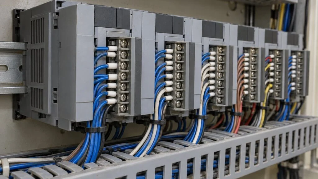
A Japanese equipment supplier sends over its signal list, the shingo risuto (信号リスト), also called the I/O list. Every row is tagged DI, DO, AI, AO, PI, or PO, and the spec column is full of notes like "a-contact," "b-contact," and "dry contact, maintained." Your job is to map each row to your PLC or DCS cards, and the first thing that trips people up is that the supplier's DI may be your DO.
The short answer: DI/DO, AI/AO, and PI/PO describe a signal's type and its direction. The first letter is the type: D is digital (ON/OFF), A is analog (such as 4–20 mA), and P is pulse. The second letter is the direction: I is input and O is output, seen from whichever panel wrote the list. This guide explains each pair, the Japanese terms you will meet on a supplier's list, and what to check row by row before anyone starts wiring.
The same signal is an output on the side that sends it and an input on the side that receives it.
Example: a flowmeter's 4–20 mA output is an AO from the flowmeter's side and an AI from the DCS side. Its totalizer pulse is a PO at the flowmeter and a PI at the DCS. Panel designers usually label signals from their own panel's side, so check which side a list was written from.
Contents
DI/DO vs. AI/AO vs. PI/PO: What Each Signal Carries
The three pairs differ in what they carry: an ON/OFF state, a continuous value, or a count. A DI signal, for example, is a digital signal coming into the panel that wrote the list.
ON/OFF, a continuous value, or a counted quantity: that is the whole difference.
O: open/close a solenoid valve, start/stop a pump
O: control valve position, VFD speed reference
O: passing a total to another device, commands to a stepper motor
Hardware names follow Mitsubishi Electric's MELSEC iQ-R lineup, where Japanese documents call a module a "unit" (yunitto). Other makers say "module" or "card."
The table below narrows the comparison to when you would use each signal and what you have to match between the two sides.
| DI/DO | AI/AO | PI/PO | |
|---|---|---|---|
| Carries | ON/OFF (two states) | A continuous, instantaneous value | A pulse count (a totalized quantity) |
| Good for | Status, faults, run commands | Monitoring readings, valve position commands | Totalized flow and energy, positioning |
| Weak point | Cannot tell you a magnitude | Not suited to totalizing | A pulse-weight mismatch corrupts the total |
| Typical forms | Dry contact, 24 V DC | 4–20 mA, 1–5 V | Contact pulse, voltage pulse |
| Specs to match | Voltage or no voltage, a/b contact, maintained or pulse | Range, which side powers the loop | Pulse weight, pulse width, maximum frequency |
Whether these signals land on a DCS or on a local control panel depends on the size of the plant.
DI/DO: ON/OFF Signals
DI stands for digital input and DO for digital output. They carry ON/OFF signals, mainly operating commands, status, and fault signals between equipment. Most run on 24 V DC instrument power, although some plants also use 100 V DC or 100 V AC signals. Which side supplies the voltage is a design choice, so it varies from project to project.
Related: Japan Industrial Voltage: 200V 3-Phase and 50/60 Hz Guide
Typical DI/DO signals include:
- Sensor inputs (proximity sensors, photoelectric sensors, limit switches)
- Pushbutton states (ON/OFF)
- Door and cover open/closed detection (safety interlocks)
- Equipment running/stopped status
- Solenoid valve open/close commands
- Start/stop signals to equipment
An open/close command to an automated valve and the valve's limit-switch feedback are a common DO/DI pair; see our guide to the jutai (valve travel timeout) alarm for how they work together.
Receiving a DI: Dry vs. Wet Contacts
When a DI comes from another piece of equipment, a common arrangement is a dry contact, called mudenatsu setten (無電圧接点, "no-voltage contact") in Japanese. The contact itself carries no voltage. Power from the receiving panel runs through the other side's contact and back to the input terminal, so the input turns ON when the contact closes.
If the other side sends a wet (voltage) contact, yudenatsu setten (有電圧接点), match the voltage type and level to your input module.
Related: How to Measure Current with a Multimeter (Japanese Testers)
Related: Dry Contact vs Wet Contact: Reading Japanese Specs
For 24 V DC inputs, the ON/OFF thresholds come from the PLC standard IEC 61131-2, which defines three input types. Type 1, intended for mechanical contacts, turns ON at 15 V or more and OFF at 5 V or less. Types 2 and 3, which also suit 2-wire sensors, turn ON at 11 V or more.
Sending a DO: Relay, Transistor, or Triac Output
On the output side, choose the output type to suit the load. Mitsubishi Electric PLCs, for example, offer three:
- Relay output: switches through a contact and works with both DC and AC loads (24 V DC or 240 V AC, 2 A per point)
- Transistor output: DC loads only. With no mechanical contact, it handles fast ON/OFF switching (12/24 V DC)
- Triac output: AC loads only (100–240 V AC)
Transistor outputs come in sink and source types, depending on which way current flows, and must match the input circuit on the other side. Check the voltage, current, and response time of each output against the datasheets for both the receiving equipment and the module.
Combining ON/OFF signals like these to run a machine is called sequence control.
Related: How to Read Japanese PLC Programs: Mitsubishi X/Y/M/D
AI/AO: Analog Signals and 4–20 mA
AI stands for analog input and AO for analog output. They carry analog signals such as 4–20 mA, mostly sensor readings for temperature, pressure, and flow, and commands to actuators such as control valves. An analog signal tells you the value at this instant, but it is a poor way to totalize a quantity over time.
Typical AI/AO signals include:
- Temperature sensor signals
- Pressure transmitter outputs
- Flowmeter analog outputs (4–20 mA and others)
- Level sensor signals
- pH and conductivity meter outputs
- Motor current and voltage monitoring
- Speed references to a VFD (inverter)
- Position commands to a proportional control valve
- Outputs to analog indicators
4–20 mA is a common signal in plant instrumentation. The bottom of the measuring range is assigned to 4 mA, the top to 20 mA, and everything in between scales linearly.
The 16 mA span covers 0–100%. Because 0% sits at 4 mA, a reading of 0 mA stands out as a fault.
Percent of range = (current − 4) ÷ 16 × 100%. On a 0–5 m level transmitter, for example, 12 mA means 50%, or 2.5 m. The current below which a signal counts as a fault is set in the receiving device or defined by the instrument's specifications.
Current is used because it holds its value over long cable runs. With 0% at 4 mA, a broken wire that drops the current to zero shows up as a fault instead of a valid zero reading.
The receiving side reads the current by passing it through a resistor and measuring the voltage. Mitsubishi Electric's R60AD4 analog input module, for example, has a 250 Ω input resistance for current input, so 4–20 mA becomes exactly 1–5 V. Whether an AI should take 4–20 mA or 1–5 V depends on the equipment specifications, so confirm this before you choose the wiring.
Related: 4-20 mA vs 1-5 V: Why Japanese Panels Use 250 Ω Inputs
PI/PO: Pulse Signals for Totals and Positioning
PI stands for pulse input and PO for pulse output. They carry pulse signals, mostly for monitoring totalized flow and totalized energy.
The sending and receiving sides agree on a pulse weight, the quantity each pulse represents, and the receiver adds that amount every time a pulse arrives. If a flowmeter is set to 1 pulse = 0.1 m³ and sends 1,200 pulses in an hour, the flow for that hour is 120 m³. This is why a pulse weight that differs between the two sides throws the total off by the same factor.
Typical PI/PO signals include:
- Pulse output from a flowmeter (pulse count = flow)
- Encoder pulse input (position and speed detection)
- Energy meter pulses (totalized kWh)
- Product counting on a conveyor line (with a photoelectric sensor)
- Step pulses to a stepper motor
- Pulse signals to an external counter or another PLC
A PO has two uses: passing a total to another device, or commanding how far a motor turns. The second is handled by a PLC positioning module.
On the receiving side, also confirm the input can keep up with the pulse rate. Mitsubishi Electric's high-speed counter module, for example, counts up to 200 kpulse/s (200,000 pulses per second) with DC input.
Related: Pulse vs Status Signals: Momentary vs Maintained Commands
Reading a Japanese Signal List (I/O List)
When two pieces of equipment connect, someone builds a signal list that lays out every signal they exchange, one row per signal. Panel design, wiring, and PLC programming are all based on this list. Here is what a few rows look like, written from the control panel's side.
Beyond type and direction, add one column for the specs to verify on each signal.
Fictional tags and specs, for illustration only. An a-contact is open at rest and closes when ON; a b-contact is the reverse.
Direction is the easiest thing to get wrong. State at the top of the list which panel it is written from, and when you compare your list with the other company's, confirm that point first.
Japanese Terms You Will See on the List
Japanese lists often use the following terms, sometimes in kanji, sometimes in a mix of kanji and English.
Each of these changes how a row has to be wired or configured.
English sources also call these Form A (NO) and Form B (NC). Confirm the meaning on the supplier's own legend if the list has one.
Tags on a signal list usually match the instrument numbers on the P&ID (piping and instrumentation diagram). If you are new to Japanese drawings in general, see how to read Japanese engineering drawings.
Related: How to Read P&ID Instrument Symbols: ISA-5.1 vs JIS
Checklist: What to Match on Every Row
Even when type and direction agree, a spec mismatch will keep the equipment from working. Check each row against the datasheets for the other equipment and for your I/O module.
- Viewpoint: which panel the list is written from, on both your list and theirs
- DI/DO: dry or wet contact, voltage and current, a-contact or b-contact, maintained or pulse
- AI/AO: range (what 4 mA and 20 mA each correspond to), which side powers the loop
- PI/PO: pulse weight, pulse width, maximum frequency
- Tags: consistent with the instrument numbers on the P&ID
Questions to Send the Japanese Supplier
If the supplier's list leaves any of these open, ask before the panel is built. The questions below can be pasted into an email as is.
- Is your signal list written from your panel's side or from ours? Please state this at the top of the list.
- For each DI/DO, is the contact dry or wet? If wet, what voltage and current?
- For each contact, is it an a-contact (NO) or b-contact (NC), and is it maintained or pulse? If pulse, what is the pulse width?
- For each AI/AO, what engineering values do 4 mA and 20 mA correspond to? Is the loop 2-wire, and which side supplies the loop power?
- For each PI/PO, what is the pulse weight, minimum pulse width, and maximum frequency?
- Do the tags match the instrument numbers on the P&ID?
Limits of This Guide
- Module names, ratings, and speeds are examples from Mitsubishi Electric's MELSEC iQ-R series. Other PLC makers use different names and values, so check the datasheet for the module you actually use.
- Which side supplies voltage, and whether 100 V signals are used, varies by project and by the designer's practice.
- The fault threshold for a 4–20 mA signal is set in the receiving device or defined by the instrument, not by this guide.
- The sample signal list is fictional.
FAQ
What Is a DI Signal?
A DI signal is an ON/OFF signal that a control panel or PLC receives from outside. It reports a switch state or whether equipment is running or faulted, as one of two states: contact closed or contact open.
Are PIO and DIO the Same as PI/PO?
No. DIO is short for digital I/O and usually refers to a digital input/output board that plugs into a PC. PIO is also used in board model names, such as Contec's PIO series, and the same maker sells input-only "PI" and output-only "PO" models. These boards handle ON/OFF signals, which is a different meaning from the pulse-based PI/PO used in instrumentation.
Can a DI Read an Analog Value?
Not directly. A DI only knows ON or OFF. If all you need is an alert when the level goes above a set point, you can feed a contact output (DO) from the instrument or an alarm unit into a DI. If you need the value itself, use an AI.
What Is the Difference Between a DI Module and a DI Unit?
None, apart from the name. Mitsubishi Electric's Japanese documents call it an "input unit," while other makers and suppliers outside Japan may say "DI module" or "input card."
Related: Retrofit Machine Monitoring on Older Japanese Machines
Sources
- I/O module types and ratings: Mitsubishi Electric, MELSEC iQ-R Series I/O modules (Japanese)
- Module categories: Mitsubishi Electric, MELSEC iQ-R Series module list (Japanese)
- High-speed counter speed (200 kpulse/s, DC input): Mitsubishi Electric, MELSEC iQ-R high-speed counter modules
- R60AD4 input ranges and 250 Ω input resistance: Mitsubishi Electric Automation, "iQ-R Series Selection Guide: Analog Input Modules" (2019)
- IEC 61131-2 ON/OFF levels for 24 V DC inputs: Beckhoff Application Note DK9222-0909-0008
- DC analog signals for process control: IEC 60381-1:1982, Analogue signals for process control systems, Part 1: Direct current signals
- Why 4–20 mA is used: Lessons In Industrial Instrumentation, "4 to 20 mA analog current signals"
- a-contact / b-contact (NC, break contact): Hokuyo Automatic, glossary
- Contec PIO and PI digital I/O boards: PIO-16/16L(LPCI)H and PI-64L(PCI)H (NTT-X Store product pages, Japanese)
Original article in JapaneseThis guide is adapted from a MONOSCOPE article written for readers in Japan: DI/DO・AI/AO・PI/POとは?信号の種類と方向の違い・使い分けと信号リストの注意点
About the editor
 MONOSCOPE EditorFOUNDER & EDITOR
Spent about ten years at a plant equipment maker and a plant engineering company, proposing, designing, and commissioning equipment, then moved into web marketing. Now a web consultant for B2B manufacturers, helping them explain their products and technology. Licensed in Japan as an Energy Manager and a Third-Class Chief Electrical Engineer.
Has run an engineering blog since 2017 (500+ articles) and a Japanese YouTube channel with about 20,000 subscribers. Each English guide is written from the Japanese shop-floor point of view and checked against the cited standards.