JIS Bolt Grades 8.8 vs 10.9 vs 12.9: Strength and Torque
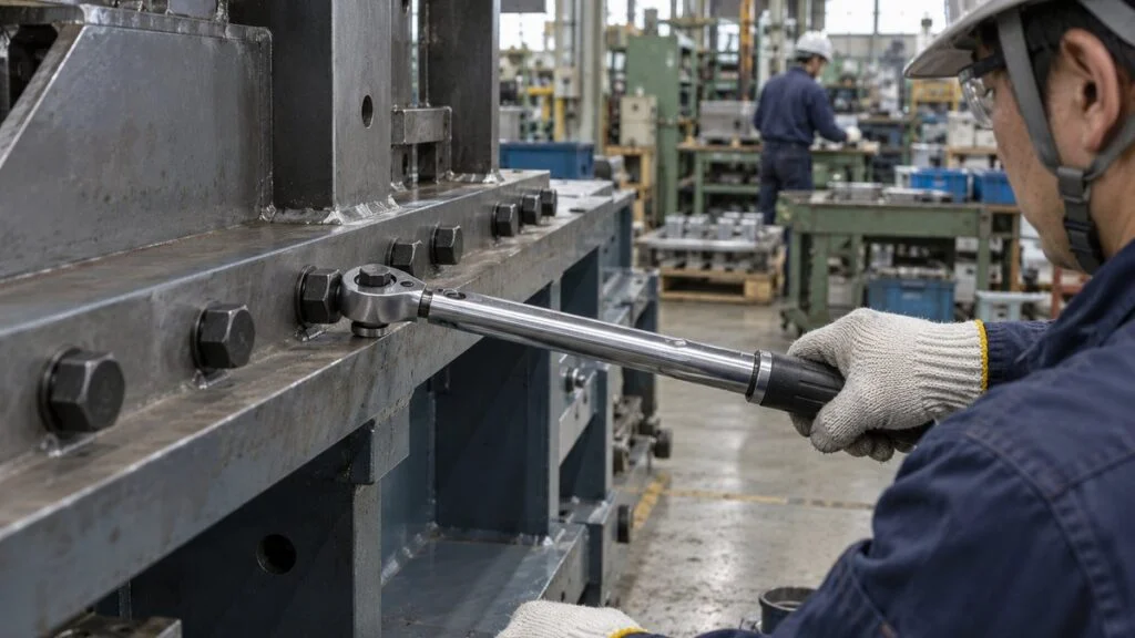
A Japanese machine arrives with an assembly drawing that lists M10 socket head bolts as 強度区分 12.9 and a tightening torque in N·m. Your maintenance team works from SAE Grade 5 and Grade 8 charts in ft-lb, and someone asks the obvious questions: Is 10.9 the same as Grade 8? Can we use the torque chart we already have? Do we need special nuts?
This guide answers those questions for engineers who work with Japanese drawings, equipment, and suppliers. It covers how to read the property classes 8.8, 10.9, and 12.9 under JIS B 1051 (the Japanese version of ISO 898-1), how they compare with SAE J429 Grade 5 and Grade 8, which nuts to pair with them, and how Japanese torque tables are calculated. The short version on torque: follow the value the designer or equipment maker specifies. A torque table is only a calculation under stated conditions; change the lubrication or plating, and the same torque gives a very different clamp force.
Contents
- JIS Bolt Grades at a Glance
- How to Read 8.8, 10.9, and 12.9
- Bolt Grade 8.8 vs 10.9 vs 12.9: Strength Compared
- Metric Property Classes vs SAE J429 Grade 5 and Grade 8
- What "JIS Bolt" Can Mean: Head Sizes That Differ From ISO
- Matching Nuts to Bolt Property Classes
- Tightening Torque vs Clamp Force
- How Japanese Torque Tables Are Calculated
- Torque, Angle, and Yield-Point Tightening in JIS B 1083
- Why Bolts Loosen After Correct Torque
- Why Bolts Break: Overtightening, Fatigue, Delayed Fracture
- Checklist Before You Tighten
- Where This Guide Does Not Apply
- FAQ
JIS Bolt Grades at a Glance
| Question | Short answer |
|---|---|
| What does 10.9 mean? | Nominal tensile strength 1000 MPa (10 × 100), yield-to-tensile ratio 0.9, so nominal yield strength 900 MPa |
| Is a JIS 10.9 bolt different from an ISO 10.9 bolt? | No. JIS B 1051:2014 is the identical Japanese adoption of ISO 898-1:2013, so the property classes and values are the same |
| Closest SAE grade? | 8.8 is usually compared with SAE J429 Grade 5, and 10.9 with Grade 8. They are comparable, not identical. SAE J429 has no grade at the 12.9 level |
| Which nut? | Nut property class 8 for bolts up to 8.8, class 10 up to 10.9, class 12 up to 12.9. A higher nut class is fine; a lower one is not |
| Which torque? | The value on the drawing, in the maker's manual, or in your plant standard. Use torque tables only as a reference, and only when their conditions match yours |
| Is 12.9 always better? | No. It is less ductile, and JIS B 1051 itself says 12.9 should be used with caution because of hydrogen embrittlement risk |
How to Read 8.8, 10.9, and 12.9
On Japanese drawings and parts lists, the property class appears as 強度区分 (kyodo kubun, "strength class"). The marking is defined in JIS B 1051:2014, which corresponds to ISO 898-1:2013. It describes the mechanical properties of carbon steel and alloy steel bolts with two numbers: the number before the dot stands for tensile strength, and the number after the dot stands for how much of that strength the bolt can take before it yields.
- Left number: nominal tensile strength in MPa (N/mm²) divided by 100.
- Right number: the ratio of nominal yield strength to nominal tensile strength, times 10.
Multiply the nominal tensile strength by that ratio and you get the stress at which the bolt starts to stretch permanently.
The two numbers separated by the dot give the nominal tensile strength and the nominal yield strength.
1 MPa = 1 N/mm². Nominal values identify the class; they are not always the same as the minimum values the standard guarantees (see the next section).
For 8.8, the nominal tensile strength is 800 N/mm² and the yield ratio is 0.8, so 800 × 0.8 = 640 N/mm² is the nominal 0.2% proof strength (the stress that leaves 0.2% permanent elongation).
The class is also marked on the part. JIS B 1051:2014 requires hexagon head bolts and hexagon socket head bolts of nominal diameter 5 mm and larger, in every property class, to carry the manufacturer's identification mark and the property class. The "8.8," "10.9," or "12.9" you see on the head comes from this rule. SAE J429 bolts use a different system: radial lines on the head (three lines for Grade 5, six for Grade 8).
This system covers carbon steel and alloy steel bolts only. Stainless steel bolts follow JIS B 1054-1:2013 (corresponding to ISO 3506-1:2009) and use a different code such as A2-70: steel grade A2 plus strength class 70, which means a minimum tensile strength of 700 N/mm² divided by 10. Strength and corrosion resistance depend on the stainless grade, so you cannot apply the carbon steel numbers to stainless bolts. For the stainless grades themselves, see SUS304, SUS316, SUS430: JIS Grades and AISI/ASTM Equivalents.
Bolt Grade 8.8 vs 10.9 vs 12.9: Strength Compared
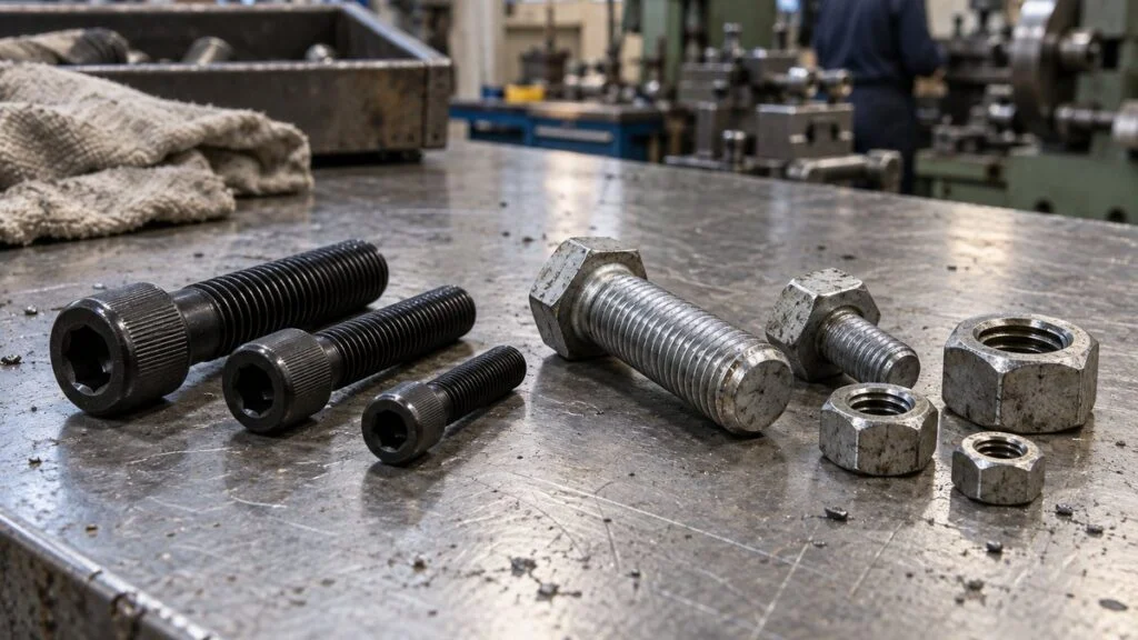
JIS B 1051 and ISO 898-1 define nine property classes: 4.6, 4.8, 5.6, 5.8, 6.8, 8.8, 9.8, 10.9, and 12.9. Machines and plant equipment mostly use 8.8, 10.9, and 12.9. Their required mechanical properties are shown below.
Tensile strength, proof strength, and proof stress rise with the class, while elongation falls.
(d ≤ 16 mm)
(d > 16 mm)
(116 ksi)
(120 ksi)
(151 ksi)
(177 ksi)
(84 ksi)
(87 ksi)
(120 ksi)
(141 ksi)
Stresses in N/mm² (= MPa); ksi values are our conversions, rounded. d = nominal thread diameter. Values from Table 3 of JIS B 1051:2014, cross-checked against the Nippon Fastener common spec table and Yura Sansyo's screw handbook. Elongation is for machined test pieces. Stress under proof load is the stress used in the proof load test: after the load is removed, the bolt must show no permanent elongation.
Note that the nominal value you calculate from the class and the minimum value the standard guarantees are not always the same. For 10.9, the nominal proof strength is 900 N/mm², but the specified minimum is 940 N/mm². For 12.9, it is 1080 N/mm² nominal versus 1100 N/mm² minimum, and torque calculations use the minimum.
At the low end, class 4.8 has a nominal tensile strength of 400 N/mm² (minimum 420 N/mm²). From 8.8 upward, the standard requires quenched and tempered carbon steel or alloy steel, so the strength comes from heat treatment.
Related: Quenching, Tempering, Annealing, Normalizing on JIS Drawings
That does not make 12.9 the safe default. As the table shows, elongation drops as strength rises, so the bolt has less ductility. JIS B 1051:2014 also states that 12.9 requires caution in use, because of delayed fracture (sudden brittle failure some time after tightening), covered later in this guide. Choose the class from the required clamp force, the strength of the mating parts, and the service environment, not on the idea that stronger is always safer.
Metric Property Classes vs SAE J429 Grade 5 and Grade 8
US shops often ask whether a metric class can replace an inch grade they already stock. The usual pairing is 8.8 ≈ SAE Grade 5 and 10.9 ≈ SAE Grade 8. Put the minimum values side by side and you can see why, and also why the pairing is only approximate.
| Metric class (ISO 898-1 / JIS B 1051) | Min. tensile | Stress under proof load | Closest SAE J429 grade | Min. tensile | Proof load stress |
|---|---|---|---|---|---|
| 8.8 (d ≤ 16 mm) | 800 MPa (116 ksi) | 580 MPa (84 ksi) | Grade 5 (1/4–1 in) | 120 ksi (827 MPa) | 85 ksi (586 MPa) |
| 8.8 (d > 16 mm) | 830 MPa (120 ksi) | 600 MPa (87 ksi) | |||
| 10.9 | 1040 MPa (151 ksi) | 830 MPa (120 ksi) | Grade 8 (1/4–1-1/2 in) | 150 ksi (1034 MPa) | 120 ksi (827 MPa) |
| 12.9 | 1220 MPa (177 ksi) | 970 MPa (141 ksi) | No SAE J429 grade at this level | — | — |
Small 8.8 bolts (d ≤ 16 mm) have a slightly lower minimum tensile strength than Grade 5, while larger 8.8 bolts are close to it. Grade 5 values also drop above 1 in (105 ksi tensile and 74 ksi proof for over 1 in through 1-1/2 in). The two systems also differ in thread form, head sizes, and test methods, so treat these pairings as a way to judge strength level, not as permission to swap parts. For 12.9 socket head bolts, inch-series socket head cap screws are made to a different specification, so confirm any substitute with the equipment maker.
What "JIS Bolt" Can Mean: Head Sizes That Differ From ISO
The property class is the same in JIS and ISO, but the hex head may not be. The Japanese hexagon bolt standard, JIS B 1180:2014, is based on ISO 4014 to ISO 4018 and related ISO standards. It also keeps an annex (Annex JA) for hex bolts that do not follow those ISO standards, to reflect how bolts are still made and used in Japan.
Those non-ISO bolts, often called "JIS-type" bolts (JIS 規格品) in Japanese catalogs, carry the older Japanese head sizes. In the 1994 and 2004 editions of JIS B 1180, the annex listed widths across flats of 17 mm for M10, 19 mm for M12, 22 mm for M14, and 32 mm for M22. ISO 4014 uses 16, 18, 21, and 34 mm for the same sizes. Older equipment, and some current Japanese stock, may therefore need a 17 mm wrench on an M10 bolt where an ISO bolt takes 16 mm.
It does not change the property class, but it affects spare parts, wrench sizes, and clearance around the head. The bearing area under the head can also differ, so confirm the tightening torque and conditions with the designer or equipment maker. When a Japanese parts list just says "M10 hex bolt," ask whether the supplier means ISO or JIS-type heads.
Matching Nuts to Bolt Property Classes
A high-strength bolt does not help if the nut is weak, because the joint then fails at the nut. Nut property classes are defined in JIS B 1052-2:2014 (corresponding to ISO 898-2:2012), and each nut class uses the same number as the left-hand number of the highest bolt class it may be paired with:
- Nut property class 8: bolts up to 8.8
- Nut property class 10: bolts up to 10.9
- Nut property class 12: bolts up to 12.9
The standard allows a nut of a higher class to replace a lower one. A class 10 nut on an 8.8 bolt is fine, but avoid the reverse, such as a class 8 nut on a 10.9 bolt.
The pairing is intentional. Regular nuts and high nuts are designed so that, if the joint is overtightened, the bolt breaks before the nut threads strip. The annex of JIS B 1052-2:2014 explains that a failure on the bolt side gives a clear sign that something went wrong during tightening.
Thin nuts (低ナット, tei-natto; property classes 04 and 05) are the exception. They have a lower load capacity and are not designed to prevent thread stripping. If space forces you to use a thin nut as the main nut, check with the designer.
Tightening Torque vs Clamp Force
When you tighten a bolt, it stretches slightly, and its pull clamps the parts together. That axial tension is the clamp force, called 軸力 (jikuryoku, "axial force") in Japanese. Clamp force is what makes the joint work, but it is hard to measure directly on the shop floor, so plants control the tightening torque (締付トルク, shimetsuke torque) instead.
JIS B 1083:2008 (general rules for tightening threaded fasteners) gives the relationship between tightening torque T and clamp force F in the elastic range, where d is the nominal diameter and K is the torque coefficient (often called the nut factor in US references):
T = K × F × d
The formula is simple; K is the hard part. JIS B 1083 notes that, with the torque method, around 90% of the tightening torque is used up by friction in the threads and under the head. Only the small remainder becomes clamp force.
So a small change in thread or bearing-surface friction gives a large change in clamp force at the same torque. As reference values, Yura Sansyo's technical data give K = 0.17 for plain (uncoated) steel with oil and 0.25 without oil, 0.24 for electro-galvanized (zinc-plated) bolts, and 0.45 for stainless steel. MISUMI's data give 0.145–0.215 with oil and 0.25–0.55 dry for black-oxide steel bolts, depending on the mating material. Both present these as guide values.
Calculated clamp force for an M10, class 10.9 bolt tightened to 55.6 N·m (41 lbf·ft), using F = T ÷ (K × d).
Yield load = minimum 0.2% proof strength 940 N/mm² × stress area 58 mm². The 55.6 N·m torque was calculated assuming K = 0.17 (see the next section). The K values are examples chosen from the ranges in MISUMI and Yura Sansyo data; the actual value must be confirmed by tightening tests.
As Figure 3 shows, a torque set for K = 0.17 gives only about two-thirds of the intended clamp force if the actual K is 0.25. The reverse is also true: if someone applies a lubricant that the spec does not call for and K drops, the same torque produces more clamp force than intended, increasing the risk of overtightening. Hitting the torque value is not the same as hitting the target clamp force.
How Japanese Torque Tables Are Calculated
The tightening torque tables published by Japanese suppliers and distributors such as MISUMI and Yura Sansyo follow the same logic. First, they cap the clamp force at 70% of the bolt's yield (proof) strength. Both companies describe the torque-method clamp force as staying within the elastic range, with 70% of the specified proof strength as the maximum. TONE, a Japanese tool maker, likewise explains that bolts are commonly tightened to about 60–70% of yield, allowing for scatter, so they stay below the elastic limit.
Next, the tables allow for scatter in clamp force with a tightening factor Q, the ratio of maximum to minimum clamp force. MISUMI and Yura Sansyo use Q = 1.4 for an oiled bolt tightened with a torque wrench. With the upper limit at 70% of yield and the lower limit at 1/Q of that, the torque aimed at the midpoint is:
TA = 0.35 × K × (1 + 1/Q) × σy × As × d
where σy is the lower yield point or 0.2% proof strength, As is the tensile stress area of the thread, and d is the nominal diameter. This is a simplified formula from supplier technical data, not a formula printed in JIS B 1083:2008. The JIS B 1083 procedure sets the target torque from the minimum and maximum torque coefficients estimated by tightening tests (such as JIS B 1084), the upper and lower clamp force limits given by the design, and the torque scatter of the tool. The simplified formula replaces that procedure with a typical K and a tightening factor Q to make the calculation easy.
Worked example for M10, class 10.9: proof strength 940 N/mm² × stress area 58 mm² gives a yield load of about 54.5 kN. The upper limit is 70% of that, about 38.2 kN; the lower limit is 38.2 ÷ 1.4 ≈ 27.3 kN; the midpoint is about 32.7 kN. With K = 0.17, the torque is 0.17 × 32.7 kN × 10 mm ≈ 55.6 N·m.
A worked example under stated assumptions, not a specified torque. Different conditions give different values.
(stress area)
(5.8)
(8.5)
(10.0)
(14.1)
(20.7)
(24.2)
(27.9)
(41.0)
(48.0)
(48.7)
(71.5)
(84)
(121)
(178)
(208)
(243)
(347)
(406)
Values in N·m, with lbf·ft in parentheses (our conversion, 1 N·m = 0.7376 lbf·ft). Calculated by MONOSCOPE from the formula above and checked against the reference torque table in Yura Sansyo's screw handbook (K = 0.17, Q = 1.4). Classes 8.8 and 10.9 match that table. For 12.9, the handbook uses a proof strength of 1098 N/mm², so its values are about 0.2% lower (65.0 N·m for M10).
These values do not mean a joint is safe at this torque. Plated bolts, dry threads, stainless steel, or aluminum or cast iron mating parts change K, and with it the clamp force. Use the torque on the drawing, the maker's specified value, or your plant standard, and check critical joints with the designer.
Figure 4 applies only to plain steel bolts, oiled, tightened with a torque wrench. For plated bolts, dry threads, stainless steel, or aluminum or cast iron mating parts, K is different and these values do not apply. Yura Sansyo's handbook makes the same point: its table values change considerably with conditions, so use them only for reference and calculate from the actual conditions. The same caution applies to any ft-lb chart for SAE bolts you already use: it was built on its own assumptions about lubrication and finish.
Some tables start from entirely different assumptions. Tohnichi, a Japanese torque tool maker, publishes a "standard tightening torque (T series)" calculated with K = 0.2 so that the axial stress on the stress area reaches 210 N/mm². It is not derived from each property class's proof strength; it is a proposal for standardizing torque at joints with no specified value. In Tohnichi's torque handbook, the T-series value for M10 is 24.5 N·m, less than half the 55.6 N·m for class 10.9 in Figure 4. Torque tables differ by source, and none of them is "the correct value."
The rule is to follow the design drawing, the equipment maker's specified value, or your plant's tightening standard. For a critical joint with no specified value, or where your conditions do not match a table's assumptions, ask the designer instead of picking a number from a table.
Torque, Angle, and Yield-Point Tightening in JIS B 1083
JIS B 1083:2008 lists three typical tightening control methods: the torque method, the turn-of-nut (angle) method, and the torque gradient method (often called yield-point tightening in English). The difference is what signal tells you to stop tightening.
The tightening factor Q is the ratio of maximum to minimum clamp force; a smaller Q means less scatter.
Q values are reference values from Table 2 of JIS B 1083:2008. The standard notes that actual scatter varies widely with factors specific to each method, so the ranges cannot be stated precisely.
The torque method is the most common. It only needs a torque wrench, but as the previous sections show, it is directly affected by friction. Keeping the bolt and nut finish and the lubrication consistent is the basic way to stabilize clamp force with this method.
Tools add error too. JIS B 1083 sets the target torque with the tool's torque scatter included, and its notes cite the then-current JIS B 4650 (hand torque wrenches): ±3% error, or ±1% for precision dial types. JIS B 4650 was withdrawn in 2008. The current JIS B 4652:2008 (hand torque tools: requirements and test methods) sets tolerances of ±4% or ±6%, depending on the tool type and maximum torque. Calibrate torque wrenches regularly and use one whose range fits the job.
Plastic-range angle tightening and the torque gradient method are used where high clamp force with little scatter is needed, such as automotive engines. JIS B 1083 warns, however, that plastic-range tightening deforms the bolt permanently, so care is needed when ductility is low or when bolts are reused. Follow the equipment maker's maintenance standard to decide whether a bolt tightened by angle may be reused.
Why Bolts Loosen After Correct Torque
In Japanese technical writing, "loosening" (緩み, yurumi) means any loss of the clamp force set at tightening. It covers nuts that turn back, and also joints that lose clamp force while the nut does not move at all. The first is rotational loosening; the second is non-rotational loosening.
Loosening without nut rotation and loosening with nut rotation have different causes and fixes.
Based on Yura Sansyo's screw handbook and Hard Lock Industry's technical data. Repeated thermal expansion and contraction, and gasket creep, also reduce clamp force.
Initial loosening is a typical form of non-rotational loosening. The clamp force is correct right after tightening, then drops as the contact surfaces settle. Retightening after a while (増し締め, mashijime) is one response, but whether and when to do it is normally set in each plant's or machine's work standard.
Rotational loosening happens at joints under repeated external loads. According to Hard Lock Industry, a Japanese locking-nut maker, repeated loads perpendicular to the bolt axis (shear direction) are the most severe of tension, torsion, and shear. Once the parts start to slip slightly, the nut is dragged around and backs off.
The basic fix is enough clamp force to stop the parts from slipping. On top of that, designers add bolts to reduce the load per bolt or arrange the structure so the external load does not act directly on the bolts. Double nuts, slotted nuts with cotter pins, thread adhesives, and locking nuts are further options to combine.
For double nuts with a thin nut, JIS B 1052-2:2014 sets the order: tighten the thin nut first, then tighten a regular or high nut against it.
Why Bolts Break: Overtightening, Fatigue, Delayed Fracture
Bolt failures are easier to diagnose if you sort them by when they happen and why: overtightening during assembly, fatigue failure from repeated loads in service, and delayed fracture that occurs suddenly some time after tightening.
When the bolt broke and how it was used are the first clues to the cause.
Based on JIS B 1083:2008, ISO 4042:2022, and Hard Lock Industry's technical data. Real failures can involve several factors, and pinning down the cause requires examining the fracture surface.
Overtightening
Once tightening passes the yield point, the bolt deforms plastically, and further tightening breaks it. If the nut or internal thread is the weaker side, the threads can strip instead. As shown in Figure 3, applying a torque meant for dry threads to a bolt coated with an unspecified lubricant produces higher clamp force than intended and pushes the joint toward this failure.
Fatigue Failure
At joints under repeated external loads, part of the load variation reaches the bolt. With enough clamp force, that share stays small. If clamp force is too low or the joint loosens, the parts separate and the full load variation goes into the bolt.
Fatigue cracks start where stress concentrates. Hard Lock Industry lists the first thread root engaged with the nut, the thread runout, and the fillet under the head. Loosening and breakage are therefore not separate problems: loss of clamp force from loosening is what triggers fatigue failure.
Delayed Fracture and Electroplated 12.9 Bolts
Delayed fracture (遅れ破壊, okure hakai) is a sudden brittle failure some time after tightening, in a bolt that showed no problem when it was installed. ISO 4042:2022, which covers electroplated coating systems for fasteners, addresses failures from hydrogen picked up during plating (internal hydrogen embrittlement).
The risk arises when three conditions occur together: high tensile strength or hardness, tensile stress, and hydrogen absorbed into the steel. Hydrogen enters during electroplating or the acid pickling before it, and harder steel is more susceptible, so the standard sets measures by property class.
Japan revised JIS B 1044 in February 2024 as an identical adoption (IDT) of ISO 4042:2022. For ISO 898-1 bolts, Table 3 of ISO 4042:2022 splits the measures by class:
- Below 10.9: no additional process verification, product testing, or baking required.
- 10.9: additional process verification and product testing, or baking (the manufacturer's choice).
- 12.9: additional process verification and product testing, plus baking.
Baking is heating after plating to drive out hydrogen. The plater and bolt maker set the temperature and time based on the standard's recommendations, the part's hardness, and the coating type. Users should not set the baking temperature and time on their own.
Pretreatment matters too. The annex of the previous JIS B 1044:2001 advised against acid pickling for parts of 385 HV or harder or property class 12.9 and above, and preferred methods without acid, such as blasting or alkaline rust removal. The same annex warned not to assume that the recommended baking prevents hydrogen embrittlement in every case. JIS B 1051:2014 also requires the manufacturer's capability, the service environment, and the tightening method to be considered when using 12.9.
JIS B 1051 further notes that, depending on the environment, even unplated bolts can suffer delayed fracture, because hydrogen can also enter from corrosion in service. For these reasons, some bolt makers do not plate 12.9 bolts. Japan's Failure Knowledge Database records a case of high-strength bolts that failed from hydrogen embrittlement after the post-plating dehydrogenation step was skipped. Do not buy black-oxide 12.9 bolts and send them to a plater yourself; if you need rust protection, ask the bolt maker. For plating callouts on Japanese drawings, see JIS Plating Callouts (Ep-Fe/Zn8/CM2) and ASTM Equivalents.
One alternative is a zinc flake coating (JIS B 1046:2020), which generates no hydrogen during coating. The standard states that this coating is applied especially to high-strength fasteners with a tensile strength of 1000 MPa or more, to avoid the risk of hydrogen embrittlement. Besides changing the coating, designers can also consider dropping one property class and getting the required clamp force from a larger size or more bolts.
Checklist Before You Tighten
Use the following order before tightening. The point is not just to find a torque number, but to confirm the conditions that number was based on.
Start by looking for a specified value. If the conditions do not match, take it back to the designer.
If there is no specified value, or the actual conditions do not match it, do not pick a value from a table yourself. Ask the designer or the equipment maker.
On the design side, a torque callout on a drawing is much harder to misread if it also states the property class, surface finish, and lubrication, not just the number. In maintenance and assembly, a switch of lubricant or a substitute bolt can change the torque coefficient without anyone noticing. A change in surface finish means the torque needs to be reviewed, so share part changes with the design department.
Related: JIS Plating Callouts (Ep-Fe/Zn8/CM2) and ASTM Equivalents
Related: How to Read Japanese Engineering Drawings (JIS B 0001)
In volume assembly, process FMEA is a useful way to list what a missed or under-torqued bolt could cause. It lets you set torque control limits, tool inspection frequency, and record-keeping in proportion to the risk.
Related: AIAG-VDA FMEA for Japanese Customers: DFMEA vs PFMEA
Questions to Ask the Japanese Supplier or Equipment Maker
- What tightening torque (or angle) is specified for this joint, and where is it documented?
- What property class are the bolts and nuts, and can we substitute a different class or an SAE inch bolt?
- Is the specified torque for dry or lubricated threads? If lubricated, which lubricant, applied where?
- What surface finish do the bolts have (plain, black oxide, zinc plating, zinc flake)? Does the torque change if we use a different finish?
- Are the hex heads ISO size or JIS-type (for example, 17 mm or 16 mm across flats on M10)?
- Is retightening required after initial run-in? If so, when and to what value?
- Can bolts tightened by angle be reused, or must they be replaced?
- For 12.9 bolts: is plating allowed, and was baking or hydrogen embrittlement testing done?
Sample Inquiry Email
Subject: Tightening torque for [machine model], [assembly name]
Hello [name],
We are preparing maintenance procedures for [machine model, serial no.]. Drawing [no.] lists M10 bolts, property class 12.9, at [assembly], but we could not find a tightening torque. Could you please confirm:
1. The specified tightening torque or angle, and the document it comes from
2. Whether the value is for dry or lubricated threads, and the lubricant if any
3. The bolt surface finish, and whether a different finish or class is acceptable
4. Whether the bolts may be reused after removal
Thank you for your help.
[Your name, company]
Where This Guide Does Not Apply
- Specified values always win. The torque tables and calculations here are examples under stated conditions. Drawings, maker manuals, and plant standards take priority.
- Stainless steel and non-ferrous bolts use different standards (JIS B 1054-1 / ISO 3506-1 for stainless) and different torque coefficients.
- Structural steel bolting (high-strength bolts for steel buildings and bridges) follows its own standards and tightening procedures, which this guide does not cover.
- Pressure equipment and piping flanges may have bolt load requirements in their own codes and gasket data. Follow the project engineering specification.
- SAE comparisons are based on minimum strength values only. Thread form, head dimensions, and test methods differ, so substitution needs the designer's approval.
- Standards change. Values here are from the editions listed in the sources. Check the current edition before using them in a specification.
FAQ
Is a JIS bolt the same as an ISO bolt?
For strength, yes: JIS B 1051:2014 is the identical Japanese adoption of ISO 898-1:2013, so a JIS 10.9 bolt and an ISO 10.9 bolt have the same required properties. Dimensions can differ, though. JIS B 1180 still includes non-ISO "JIS-type" hex bolts, whose M10, M12, M14, and M22 heads differ in size from ISO 4014.
What is the difference between bolt grade 8.8 and 10.9?
A 10.9 bolt has a minimum tensile strength of 1040 MPa and a minimum 0.2% proof strength of 940 MPa, compared with 800–830 MPa and 640–660 MPa for 8.8. In the calculated example in Figure 4, an M10 10.9 bolt takes 55.6 N·m versus 37.9 N·m for 8.8 under the same conditions. 10.9 also requires a nut of property class 10 or higher and has stricter hydrogen embrittlement measures when electroplated.
Is 10.9 the same as SAE Grade 8?
They are comparable, not identical. Their minimum tensile strengths (1040 MPa vs 150 ksi, or 1034 MPa) and proof stresses (830 MPa vs 120 ksi, or 827 MPa) are very close, but the two systems differ in threads, dimensions, and test methods. Likewise, 8.8 is close to SAE Grade 5.
Can I use a 12.9 bolt instead of 10.9 to be safe?
Not without the designer's approval. 12.9 is less ductile, JIS B 1051 calls for caution in its use because of delayed fracture, and at the same diameter and torque coefficient, the same torque gives the same calculated clamp force whatever the property class, so switching to 12.9 alone adds no clamp force. Electroplated 12.9 bolts need extra measures under ISO 4042.
Why are Japanese torque values different from my torque chart?
Each table rests on its own assumptions about the torque coefficient (lubrication and finish), the target percentage of yield, and the scatter allowance. Japanese supplier tables typically use K = 0.17 (oiled plain steel), a 70% of proof strength upper limit, and Q = 1.4, while Tohnichi's T series uses a much lower stress target. Compare the assumptions, not just the numbers, and follow the specified value.
Sources
- Property class designation, marking, and the 12.9 caution: JIS B 1051:2014, Mechanical properties of fasteners made of carbon steel and alloy steel — bolts, screws and studs with specified property classes (identical to ISO 898-1:2013, Japanese); Japanese Standards Association, JIS B 1051:2014 listing (Japanese)
- Mechanical properties by class: JIS B 1051:2014 Table 3 (above); Nippon Fastener, common spec table (Japanese); Yura Sansyo screw handbook, mechanical properties (2) (Japanese)
- SAE J429 Grade 5 and Grade 8 values: Baco Enterprises, SAE J429 specification
- Property class steps and nut pairing: Yura Sansyo screw handbook, property class designation for steel bolts and nuts (Japanese); JIS B 1052-2:2014, nuts with specified property classes (ISO 898-2:2012, Japanese)
- Hex bolt dimensions: JIS B 1180:2014 preview, Japanese Standards Association (Japanese); Global Fastener, JIS B 1180 annex tables; Wermac, hex bolt dimensions (DIN 931 / ISO 4014)
- Stainless steel bolts: JIS B 1054-1:2013, corrosion-resistant stainless steel fasteners — Part 1: bolts, screws and studs (ISO 3506-1:2009, Japanese)
- Torque–clamp force relationship and tightening methods: JIS B 1083:2008, general rules for tightening of threaded fasteners (Japanese); TONE, tightening control methods (Japanese); Ikeda Kinzoku, tightening control methods (Japanese)
- Torque coefficients, tightening factors, torque formula and reference tables, loosening types: Yura Sansyo, proper tightening of threaded fasteners; Yura Sansyo, mechanical properties and reference tightening torque; MISUMI, proper bolt clamp force and tightening torque (all Japanese)
- Standard tightening torque (T series): Tohnichi FAQ; Tohnichi torque handbook, chapter 2 (Japanese)
- Hand torque tool tolerances: JIS B 4652:2008, hand torque tools — requirements and test methods (Japanese)
- Loosening and fatigue failure: Hard Lock Industry, why threads loosen; Hard Lock Industry, how loosening leads to bolt fatigue failure (Japanese)
- Electroplating and hydrogen embrittlement: ISO 4042:2022, Fasteners — Electroplated coating systems; JIS B 1044:2024 listing (identical to ISO 4042:2022, Japanese); JIS B 1044:2001 (previous edition) (Japanese)
- Zinc flake coatings: JIS B 1046:2020, non-electrolytically applied zinc flake coating systems for fasteners (Japanese)
- Plating limits on 12.9 and failure case: Nippon Fastener Q&A; Failure Knowledge Database, electroplated high-strength bolts failed by hydrogen embrittlement (Japanese)
Original article in JapaneseThis guide is adapted from a MONOSCOPE article written for readers in Japan: ボルトの強度区分と締付トルクの決め方|8.8・10.9・12.9の疑問9つ
About the editor
 MONOSCOPE EditorFOUNDER & EDITOR
Spent about ten years at a plant equipment maker and a plant engineering company, proposing, designing, and commissioning equipment, then moved into web marketing. Now a web consultant for B2B manufacturers, helping them explain their products and technology. Licensed in Japan as an Energy Manager and a Third-Class Chief Electrical Engineer.
Has run an engineering blog since 2017 (500+ articles) and a Japanese YouTube channel with about 20,000 subscribers. Each English guide is written from the Japanese shop-floor point of view and checked against the cited standards.