VA vs W: Apparent vs Real Power and How to Read UPS Specs
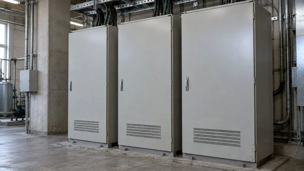
A control panel is on its way from Japan. The supplier's spec sheet says "3φ AC200V, 10kVA," the UPS inside it is listed as "1kVA / 0.6kW," and your plant runs on 480 V or 400 V. Before you size the feeder, the breaker, or a replacement UPS, you need to know what each of those numbers actually means and which assumptions sit behind them.
The short answer: VA (volt-amperes) is the unit of apparent power, the product of voltage and current. W (watts) is the unit of active power, also called real power, the power a load actually uses. Power factor links the two. A 1,000 VA load with a power factor of 0.8 draws 800 W, but an 800 W load does not necessarily run on an 800 VA supply. You have to check both values.
This guide covers the Japanese terms you will see in specs, single-phase and three-phase calculations (including how the same load converts to current at 200 V, 400 V, and 480 V), the two output limits on every UPS, motor nameplates, and power factor correction. It ends with a checklist, questions for the Japanese supplier, and an inquiry email you can adapt.
Contents
- Japanese Power Terms You Will See in Specs
- What Is VA (Apparent Power)?
- What Is W (Active Power)?
- Three-Phase: kVA to kW and Amps
- How to Read UPS Specs: Two Output Limits
- Cables and Breakers: Convert to Amps
- Energy: Multiply W by Operating Hours
- Power Factor Correction: Same kW, Less Current
- Quick Reference: Which Value to Check
- Checklist: Before You Size the UPS, Breaker, or Supply
- Questions for the Japanese Supplier
- Limits of This Guide
- FAQ
- Sources
Japanese Power Terms You Will See in Specs
Japanese datasheets and single-line diagrams use a small set of terms for power. They map directly to the English terms, but you need to know which is which before you can read the numbers.
| Japanese | Reading | English | Unit |
|---|---|---|---|
| 皮相電力 | hiso denryoku | Apparent power (S) | VA, kVA |
| 有効電力 | yuko denryoku | Active power, real power (P) | W, kW |
| 無効電力 | muko denryoku | Reactive power (Q) | var, kvar |
| 力率 | rikiritsu | Power factor (PF) | Ratio (0–1) |
| 効率 | koritsu | Efficiency | % or ratio |
| 電力量 | denryokuryo | Energy | kWh |
| 線間電圧 | senkan den'atsu | Line-to-line voltage | V |
| 線電流 | sen denryu | Line current | A |
| 単相 / 三相 | tanso / sanso | Single-phase / three-phase (often written 1φ / 3φ) | — |
| 定格出力 | teikaku shutsuryoku | Rated output (for a motor, shaft output) | kW |
| 進相コンデンサ | shinso kondensa | Power factor correction capacitor | kvar |
What Is VA (Apparent Power)?
VA stands for volt-ampere, the unit of apparent power, S. In a single-phase AC circuit, S is the RMS voltage times the RMS current: 100 V at 10 A is 1,000 VA.
The RMS (root-mean-square) value is the DC value that would heat a resistor by the same amount. AC changes size and direction over every cycle, but when you are working out how much current a cable or a device has to carry, RMS is the value that counts. For a sine wave, the peak voltage is higher than the RMS voltage.
The 100 V or 200 V you put into a power formula is the RMS value. Multiplying peak values gives you a different, wrong apparent power.
VA Tells You How Much Current Flows
At a given voltage, more apparent power means more current. Sources, transformers, and cables all have to carry that current, so active power alone does not tell you the load on them.
At 100 V single-phase, a 1,000 VA load draws 10 A and a 1,500 VA load draws 15 A. Two loads with the same active power but different power factors draw different currents, and so need different supply capacity and wiring.
That is why transformers are rated in kVA. How much active power a transformer can deliver also depends on the power factor of the load, so do not read "10 kVA" as "10 kW" without knowing that power factor.
Watch the prefixes too: 1 kVA = 1,000 VA and 1 kW = 1,000 W. Mixing up kVA and VA is one mistake; mixing up apparent power and active power is another.
If you know the voltage and current of a single-phase circuit, you can calculate the apparent power. You cannot calculate the active power the same way.
That takes the power factor or a power meter reading. Multiplying an ammeter reading by the voltage does not necessarily give you the active power consumed.
Example: single-phase, 100 V, 10 A, load with an assumed true power factor of 0.8. The voltage is measured across the load; the current is the line current.
The current arrow shows the reference direction for the RMS value; AC does not flow in one direction. For real measurements, use instruments and connections rated for the circuit.
Rated VA vs. Measured VA
A rated capacity on a spec sheet is the range the device is designed for. At light load, the actual current and power are lower, so the rated figure is not what the device draws all the time.
The reverse also holds: one low current reading is not enough to size a supply. Work out the maximum operating condition, starting, loads that run at the same time, and future loads, and compare each against the spec.
When a nameplate lists several voltages or frequencies, take the voltage and current from the same row. Multiplying a voltage from one supply condition by a current from another produces an apparent power that matches no actual rating. Also check what the figure covers.
The input rating of a whole machine and the rating of a component inside it are different things. Use the single-line diagram and the item names in the spec to see whether a VA figure covers only the control power supply or the entire input, including motors and auxiliaries.
What Is W (Active Power)?
The watt is the unit of power, and in AC circuits it is used for active power, P: the power that actually passes from the source to the load and turns into heat, light, or mechanical output. One watt is one joule per second. Power is the rate of energy use; energy is the total over time.
Active power includes losses inside the device as well as useful output. Not all of the 800 W going into a motor comes out at the shaft, and efficiency is the figure that tells you how it splits.
Multiply Instantaneous Voltage and Current, Then Average
The basic definition of AC active power is the average of instantaneous voltage times instantaneous current. The instantaneous power, p, varies over the cycle, and its average is P. When both voltage and current are sine waves with a phase difference θ, that average works out to V I cos θ, where V and I are RMS values and cos θ is the power factor.
For an ideal resistive load, voltage and current move together, so θ = 0 and cos θ = 1. In that case P = VI holds for AC as well, so "P = VI only works for DC" is the wrong rule to remember.
P = VI also works for steady DC, but for AC you need to check the waveform and the power factor. If you go back to the principle, the average of instantaneous products, it is easier to see when each formula applies.
Reactive Power Is Not the Same as Loss
Inductors and capacitors store energy in magnetic or electric fields and return it to the source. In ideal components this happens every cycle, and the net energy consumed over a full cycle is zero.
For sine waves, the quantity that describes this exchange is reactive power, Q, measured in var. Lagging (inductive) and leading (capacitive) loads are distinguished by direction or sign.
Reactive power is not wasted active power. It is tied to useful functions such as building the magnetic field in a motor. The current that carries it, though, causes real resistive losses in the wiring, so it still adds to the burden on the installation.
With 800 W of active power and 600 var of reactive power, the apparent power is 1,000 VA, not 1,400. The three values form a right triangle: P and Q are the two sides, and S is the hypotenuse. A common analogy treats VA as a container holding W and var side by side, but adding them that way leads to wrong answers.
Power triangle for an inductive load with sine waves, drawn with sides in the ratio 800 : 600 : 1,000.
The horizontal and vertical sides are different components of power. The triangle illustrates S² = P² + Q²; it does not mean you add W and var to get VA.
Power Factor vs. Efficiency
Power factor is active power divided by apparent power, P/S, often written λ. For a load that draws power, it ranges from 0 to 1 and tells you how much current it takes to deliver a given active power.
Efficiency is a different ratio: the share of input active power that becomes useful output. For a motor, it compares electrical input with mechanical output, and the difference is lost as heat, friction, and so on.
A power factor of 0.8 does not mean 20% of the input is lost as heat. Nor does 90% efficiency imply a power factor of 0.9.
When both ratios appear in the same table, check the numerator and denominator of each.
To estimate supply capacity from a motor's shaft output, work back in two steps: divide by efficiency to get input active power, then divide by power factor to get apparent power. Keeping the steps separate stops you from mixing up losses and reactive power.
Distorted Waveforms: Use True Power Factor
Equipment with rectifier front ends can draw current that is not a sine wave. Then a single phase angle cannot describe the whole current, and cos θ of the fundamental may not equal the overall power factor.
True power factor is P/S, with S calculated from RMS values. Displacement power factor is the cosine of the angle between the fundamental voltage and current, so it reflects only the fundamental.
Even when the fundamentals line up well, a heavily distorted current has a higher RMS value. Current goes up without a matching rise in active power, so do not treat the two power factors as interchangeable. A power meter calculates active power from simultaneous samples of voltage and current.
When you read its spec, check whether "power factor" means the total value or the fundamental-only value, and which calculation method it uses. For distorted three-phase circuits, meters can also calculate apparent and reactive power differently. Before you compare readings from two instruments, align the wiring method and the calculation definitions instead of assuming one meter is faulty.
Three-Phase: kVA to kW and Amps
For a balanced three-phase system with sine waves, you can find the total power from the line-to-line voltage and the line current. The single-phase VI gains a factor of √3, not 3. Three wires do not make it 3VI.
Here, V is the line-to-line voltage between two conductors, and I is the current in one line between the source and the load. Mixing in the phase voltage across one load phase, or the phase current through one winding, puts the √3 in the wrong place. In a wye (Y) connection, the phase voltage is 1/√3 of the line-to-line voltage.
In a delta (Δ) connection, the phase current is 1/√3 of the line current.
Related: Japan Industrial Voltage: 200V 3-Phase and 50/60 Hz Guide
Adding up the active power of each phase works for any circuit. Reducing it to one formula with line-to-line voltage and line current, though, requires balanced, sinusoidal conditions. For unbalanced or distorted circuits, measure with a power meter wired for the circuit, and check how it calculates per-phase and total values.
Worked Example: 200 V, 30 A, Power Factor 0.85
Take a pump circuit on a balanced, sinusoidal three-phase 200 V supply drawing a 30 A line current at a power factor of 0.85. The 200 V is line-to-line, the 30 A is line current, and the result is the power on the supply side where you measured.
Rounded, that is about 10.4 kVA, 8.8 kW, and 5.5 kvar. Rounding too aggressively in intermediate steps can change the final result, so round at the same stage and to the same number of digits as the document you are comparing against.
Once √3VI gives you the three-phase total, do not multiply by 3 again. Writing the variable definitions into the calculation sheet makes this easy to check.
Balanced wye-connected load. The voltmeter is across two lines; the current is in one supply line.
The load is a balanced set of equal impedances. This is a concept diagram of what is measured, not a connection procedure.
Working Back From kW to kVA and Amps
If a load takes 8 kW from the supply at a power factor of 0.8, it needs 8 ÷ 0.8 = 10 kVA. kW and kVA are the same number only at a power factor of 1, so an 8 kVA source cannot supply this load. On a three-phase 200 V supply, 10 kVA means a line current of about 28.9 A. The same 8 kW draws a different current at a different voltage or power factor, so never reuse a current value without its conditions.
For a generator or UPS, this 10 kVA is the steady-state starting point. Final selection also has to account for the kW limit, voltage dip during starting, load characteristics, and operating conditions, all checked against the manufacturer's application data.
Same Load, Different Voltage: 200 V vs. 400 V vs. 480 V
Japanese factory equipment is commonly built for a 200 V class or a 400 V class three-phase supply, and Japan runs on 50 Hz in the east and 60 Hz in the west. Your site may be on 480 V or 208 V at 60 Hz (common US system voltages) or 400 V at 50 Hz (the IEC 60038 nominal value used in many countries). The kVA of a load does not change with voltage, but the line current does, and that current is what sizes cables and breakers.
| Line-to-line voltage | Line current per 10 kVA (balanced three-phase) |
|---|---|
| 200 V | 28.9 A |
| 208 V | 27.8 A |
| 380 V | 15.2 A |
| 400 V | 14.4 A |
| 415 V | 13.9 A |
| 480 V | 12.0 A |
Recalculating the current is the easy part. Whether a 200 V-class machine can run directly on your supply, needs a step-down transformer, or should be ordered in a 400 V-class version is a question for the supplier. Motors rated for both 50 Hz and 60 Hz often list a different rated current and speed for each frequency, so read the row that matches your site.
A Motor's Nameplate kW Is Not Its Input Power
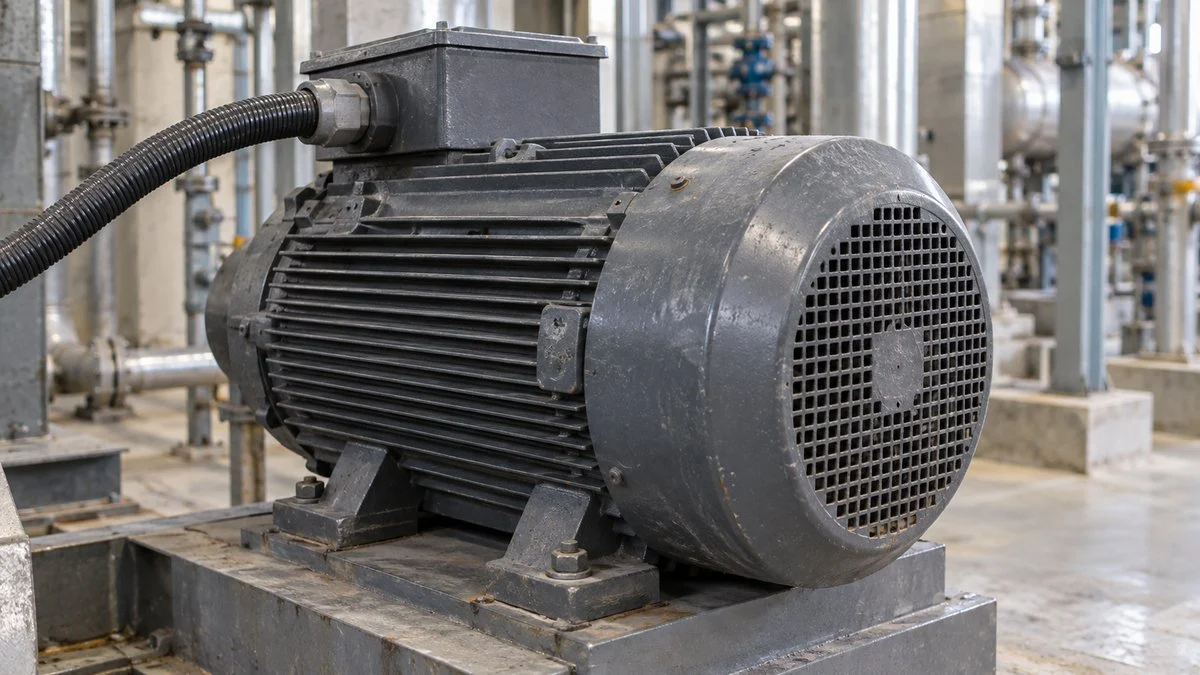
A motor's rated kW is normally its mechanical output at the shaft. Input active power also includes losses, so a 7.5 kW motor does not always draw 7.5 kW from the supply. Suppose the shaft output is 7.5 kW and, at that operating point, the efficiency is 0.90 and the power factor is 0.80.
The input active power is then about 8.33 kW. Dividing by the power factor gives an input apparent power of about 10.42 kVA, or a line current of about 30.1 A at three-phase 200 V.
With an efficiency of 0.90, about 0.83 kW of the 8.33 kW input is lost. Do not treat the gap between 8.33 kW and 10.42 kVA as additional heat loss. That difference comes from the power factor, not from losses.
When you compare motor types, the same output does not mean the same input either. Efficiency, load factor, and drive method all change what the supply sees.
Assumed efficiency 0.90 and power factor 0.80. The thick arrows show the flow of active power, not a flow of VA.
The motor is a simplified outline and does not show internal construction. Arrow widths are not to scale, and losses are shown as one lump. The calculation uses the unrounded value of 7.5 ÷ 0.9.
With a Variable Frequency Drive, Define Where You Measure
When a variable frequency drive (VFD, often called an inverter in Japanese documents) runs the motor, the power at the motor terminals and the power drawn by the drive from the supply are different. For supply sizing, include the drive's losses and its input power factor.
You cannot apply the motor's power factor to the drive input, because the waveforms and supply-side conditions differ. Use the drive's input specification or a suitable measurement.
Running fans and pumps at reduced speed changes the active power they need. That is a different mechanism from power factor correction. Drive output is not a utility sine wave, so the meter must be rated for it.
State whether a reading is from the input or output side, and compare values taken at the same time and under the same load.
How to Read UPS Specs: Two Output Limits
A UPS has two output limits, one in VA and one in W, and the load must stay within both. Some Japanese UPS datasheets show both in one line, such as "1kVA / 0.6kW" or "1000VA / 600W." Take a hypothetical UPS rated 1,000 VA and 600 W:
- Load A, 900 VA and 540 W: within both limits.
- Load B, 700 VA and 630 W: within the VA limit but over the W limit.
- Load C, 1,100 VA and 550 W: within the W limit but over the VA limit.
Staying under one limit is not enough if the load exceeds the other. Also, the 600 W ÷ 1,000 VA = 0.6 on this UPS is not the power factor of the equipment you plug into it. One is the ratio between the UPS's two output limits; the other is P/S measured at the load.
VA increases to the right and W increases upward. The shaded area meets both output limits and P ≤ S.
Scale: 1 VA = 0.5 px horizontally, 1 W = 0.4 px vertically. The chart includes P ≤ S for consuming loads. It is not the load-capability curve of any actual model.
The ratio between the two limits depends on the model. APC (Schneider Electric) notes that a watt rating of about 60% of the VA rating used to be the industry norm, but newer UPSs have watt ratings closer to their VA ratings; some current models are rated at a power factor of 0.9 or 1.0.
So a Japanese spec that lists only kVA does not tell you the kW limit. Ask for both.
When several devices share one UPS, follow the manufacturer's sizing procedure and total the maximum VA and the maximum W separately. Check simultaneous operation, inrush current, and compatibility with the UPS output waveform as well. A small sum of nameplate ratings is not enough to decide.
Runtime is a separate question from capacity. Check the UPS topology as well, and evaluate runtime using the manufacturer's runtime table or conditions for the load's W.
Cables and Breakers: Convert to Amps
For cables and breakers, do not compare VA with a current rating. Convert to current using the circuit voltage and number of phases: 1,000 VA at 100 V single-phase is 10 A, but three-phase uses the √3 formula above.
At the same kW, a lower power factor means more current, so comparing cable loading in kW alone can leave you undersized. Line up voltage, power factor, and efficiency, and define the maximum design load.
The current is only an input to cable and breaker selection, and the final choice belongs to a qualified electrical engineer or installer. Installation method, ambient temperature, grouping, voltage drop, and short-circuit protection all apply under your local electrical code. For loads with starting current, such as motors, treat running current and starting conditions separately.
A breaker rated above the running current does not by itself tell you whether it will trip on start-up or protect the circuit under a fault. You need both enough current capacity and the right protection: at this stage, also check what the molded case circuit breaker (often labeled NFB on Japanese drawings) and any earth-leakage breaker (ELB) actually protect against.
Related: NFB Breaker vs. MCCB vs. ELB: Japanese Circuit Breaker Terms
Energy: Multiply W by Operating Hours
At constant active power, energy is active power times time, in kWh. A kW figure alone does not tell you the total energy used.
Running at an average of 8.8 kW for 6 hours uses 52.8 kWh. The same 8.8 kW machine uses much less energy if it runs briefly than if it runs all day.
Multiplying the nameplate kW by operating hours can differ from actual energy, depending on operating conditions. To compare energy savings, align operating hours, load, and production volume, and check the active energy for the period that matters. For electric heating, keep the heat the product needs separate from the energy drawn from the supply, which includes losses.
Electricity bills often include charges tied to contract terms or peak demand as well as energy, so estimate kWh savings and tariff effects separately.
Related: kcal/h to kW, BTU/h, and Tons: Chart for Japanese Specs
Power Factor Correction: Same kW, Less Current
For a load using the same active power at the same voltage, raising the power factor reduces the apparent power required. Current drops too, which frees up supply capacity and reduces resistive losses in the wiring upstream of the correction point.
Take a balanced three-phase 200 V load of 10 kW. At a power factor of 0.8, it needs 12.5 kVA and about 36.1 A per line. At 0.95, it needs about 10.53 kVA and about 30.4 A.
The 10 kW itself has not changed. What drops is the current needed to deliver it and the reactive power in the compensated section.
With the same wiring resistance, resistive loss scales with the square of current, so the loss ratio here is about 0.71. That does not mean the plant's total consumption falls by about 29%.
Power factor correction capacitors are a common way to offset lagging reactive power from inductive loads. Size and placement depend on the installation. Leaving oversized capacitors connected when the load drops can push the power factor too far into the leading region, so read the direction (leading or lagging) and the operating state along with the number.
On systems with harmonics, capacitors, reactors, and the supply interact. Adding capacitance will not always help; assess harmonics, resonance, and existing equipment together.
Some tariffs apply a discount or surcharge based on power factor, depending on the tariff plan and how it calculates power factor, so do not confuse a one-off reading with the averaged power factor used for billing.
Quick Reference: Which Value to Check
The unit you need depends on what you are evaluating: capacity, current, or energy. Decide which part of the system you are assessing first, then read the V, A, W, VA, and power factor at that point.
Not a choice between VA and W: each row shows the main value and the conditions that go with it.
| Situation | Main value | Also check |
|---|---|---|
| Transformer or generator capacity | kVA, rated voltage and current | Generator kW limit, load power factor, starting, temperature and operating conditions |
| UPS output capacity | Both VA and W limits | Maximum load, waveform and inrush compatibility, required runtime |
| Cables and breakers | A | Installation, ambient temperature, voltage drop, short-circuit protection, starting |
| Power consumption and energy savings | kW, kWh | Measurement boundary, average vs. peak, operating hours, production conditions |
| Power factor correction capacitors | kvar, leading or lagging | Load variation, correction point, existing capacitors, harmonics and reactors |
| Motor nameplate | Shaft output kW, V, A, efficiency, power factor | Input vs. output, frequency, load factor, drive method |
Use this table as a starting point for reading specs. Do not skip selection conditions, for example by setting a protective device rating from current alone.
When the Spec and Your Measurement Don't Match
- Input or output? Check whether each figure is an input or an output value. Motor shaft output vs. panel input, or UPS output limit vs. connected load, are different things.
- Units and variables. Align single-phase vs. three-phase, line-to-line vs. phase values, V vs. kV, and VA vs. kVA. A factor of 1,000 or √3 usually points to units or variables before it points to a faulty device.
- Meter setup. Have a qualified electrician or the meter manufacturer confirm the wiring method, voltage-to-current pairing, CT and VT ratios, and current direction. A wrong ratio setting shifts the reading even when the meter is working correctly.
- Operating conditions. Compare load factor, time of day, whether starting is included, and average vs. maximum. Do not adjust assumed power factor or efficiency just to make mismatched readings agree.
Checklist: Before You Size the UPS, Breaker, or Supply
- Voltage and frequency: rated voltage and frequency of each load (200 V class or 400 V class, 50 Hz or 60 Hz), and your site's voltage and frequency
- Phases: single-phase or three-phase; for three-phase, confirm the figure is line-to-line voltage and line current
- What the number covers: whole-machine input, control power only, or one component; input or output
- kVA and kW: both values, plus the power factor used to convert between them and whether it is true or displacement power factor
- Peaks: maximum demand, starting or inrush current, and loads that run at the same time
- UPS: output limits in both VA and W, output waveform, and runtime at your actual W load
- Drives: input-side current and power factor of any VFD, not the motor's values
- Motors: shaft output, efficiency, power factor, and rated current at your voltage and frequency
- Rounding: calculation sheets that state variable definitions and where values were rounded
Questions for the Japanese Supplier
- Is the "電源容量" (dengen yoryo, supply capacity) figure in kVA or kW, and does it cover the whole machine including motors, heaters, and auxiliaries?
- What power factor did you assume to convert between kVA and kW?
- What is the maximum current per line at our voltage, including starting or inrush?
- Is the equipment rated for 200 V class or 400 V class? Is a version for our voltage and frequency available, or do we need a transformer?
- What are the UPS output limits in both VA and W, and what runtime does it give at our load in W?
- For each motor, what are the shaft output, efficiency, power factor, and rated current at our frequency?
- Are any power factor correction capacitors or harmonic filters built in?
Sample Inquiry Email
Short, numbered questions are easier for the Japanese side to answer item by item and to run through translation tools. Adapt this template:
Subject: Power supply data for [equipment name / order no.]

Dear [Name],

We are preparing the power supply for [equipment name]. Our site supply
is [480 V / 400 V], 3-phase, [60 / 50] Hz. Could you please confirm:

1. Rated input voltage and frequency of the equipment
2. Total input capacity in both kVA and kW, and the power factor used
3. Maximum line current at our supply voltage, including starting/inrush
4. UPS model, output rating in both VA and W, and runtime at our load
5. Shaft output (kW), efficiency, power factor, and rated current of each motor
6. Whether a transformer is required, or a version for our voltage is available

A table or the relevant pages of the specification would be fine.

Best regards,
[Your name]
Limits of This Guide
- The formulas using cos θ and sin θ assume sine waves, and the √3 three-phase formulas assume balanced conditions. Distorted or unbalanced circuits need appropriate measurement.
- All numerical examples, including the 1,000 VA / 600 W UPS and the 7.5 kW motor, are fictional and for illustration only. Use datasheet values for actual equipment.
- Cable, breaker, and transformer sizing depends on local codes and site conditions, which this guide does not cover.
- Whether 200 V-class equipment can run on your supply, and how starting affects a generator or UPS, depend on the specific equipment. Confirm with the supplier and manufacturer.
- Tariff rules on power factor vary by country and utility.
- This guide explains how to read specifications. It is not a wiring, measurement, or installation procedure. Have a qualified electrician carry out any work on the electrical system.
FAQ
How Many Watts Is 1,000 VA?
It depends on the load's power factor: W = VA × power factor. At 0.8, 1,000 VA is 800 W; at 1, it is 1,000 W. The VA figure alone does not fix a single watt value.
How Do I Convert kVA to kW for Three-Phase?
The same way as for single-phase: kW = kVA × power factor. The √3 only enters when you go from kVA to amps: I = kVA × 1,000 ÷ (√3 × line-to-line voltage). For example, 10 kVA at 400 V is about 14.4 A.
Can I Assume a Power Factor of 1 if I Don't Know It?
Not by default. Which way the error goes depends on what you are calculating.
When you work out the VA needed from a W figure, assuming 1 gives too small a result if the real power factor is below 1. Check the spec or ask the manufacturer.
Is W Always Equal to VA for a Heater?
For an ideal resistor on a sine-wave supply, yes: there is no phase difference, so the power factor is 1. Real equipment may include power controllers or auxiliaries, so confirm before assuming the whole machine's input is the same.
If Power Factor Improves, Does Motor Efficiency Improve by the Same Amount?
Not necessarily. Power factor and efficiency are different ratios, so they do not move in proportion. Evaluate the change in current and wiring losses from power factor correction separately from the motor's efficiency in converting input to shaft output.
Can I Use the Average Current When the Phase Currents Differ?
Putting an average current into the balanced √3VI formula may not give the correct total active power. Use a measurement method suited to unbalanced circuits, and check how per-phase and total values are calculated.
Sources
- RMS values, active power, and true power factor: Tektronix, "Fundamentals of AC Power Measurements"
- AC power and how power meters work: Yokogawa Test & Measurement, basics of AC power and power measurement (Japanese)
- Three-phase power and energy: Mitsubishi Electric, e-learning on three-phase AC circuits (Japanese)
- Power calculation methods for distorted three-phase circuits: HIOKI, PW4001 power calculation formulas (Japanese)
- True vs. displacement power factor: Power Monitors, "PF vs DPF: What's the Difference?"
- UPS VA and W limits in Japanese specs: OMRON, UPS specification items (Japanese)
- UPS selection conditions: Schneider Electric FAQ (Japanese)
- Watt and VA ratings of a UPS, the 60% norm, newer 0.9/unity models: Schneider Electric blog, "VA vs Watts: What's the Difference Anyway?"; APC FAQ FA157485
- Motor input, output, and efficiency: Nidec, motor basics (Japanese)
- Supply capacity for inverters (VFDs): Mitsubishi Electric FA FAQ (Japanese)
- Handling power factor correction capacitors: Japan Electrical Manufacturers' Association (JEMA) (Japanese)
- 50 Hz / 60 Hz split in Japan: Wikipedia, "Electricity sector in Japan"
- 200 V-class and 400 V-class motor ratings by frequency: Mitsubishi Electric, IE3 induction motors
- 230/400 V nominal voltage: Wikipedia, "IEC 60038"
- US nominal system voltages (208Y/120 V, 480Y/277 V): EC&M, "Voltage Variations"
Original article in JapaneseThis guide is adapted from a MONOSCOPE article written for readers in Japan: VAとWの違いとは?皮相・有効・無効電力の計算と三相・UPSの使い分け
About the editor
 MONOSCOPE EditorFOUNDER & EDITOR
Spent about ten years at a plant equipment maker and a plant engineering company, proposing, designing, and commissioning equipment, then moved into web marketing. Now a web consultant for B2B manufacturers, helping them explain their products and technology. Licensed in Japan as an Energy Manager and a Third-Class Chief Electrical Engineer.
Has run an engineering blog since 2017 (500+ articles) and a Japanese YouTube channel with about 20,000 subscribers. Each English guide is written from the Japanese shop-floor point of view and checked against the cited standards.