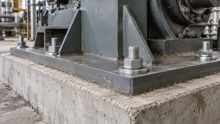
Datum Selection in GD&T: JIS vs ASME on Japanese Drawings
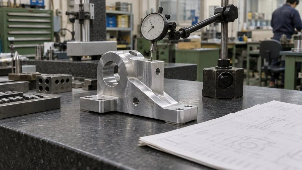
A Japanese drawing arrives with a feature control frame that reads "position Ø0.1 | A | B | C." Your shop measures the part and it passes. Then the Japanese customer's incoming inspection rejects it. In many of these disputes, the part is not the problem. The problem is how each side chose, read, or physically reproduced the datums.
A datum is the reference used to establish a geometric tolerance zone on a drawing. On Japanese drawings, datums follow JIS B 0022 and JIS B 0021, which are based on older ISO editions. If you work under ASME Y14.5, most of the logic carries over, but the terms, the standard editions, and a few defaults differ.
This guide covers how Japanese designers are taught to select datums, how to set primary, secondary, and tertiary precedence, why datum measurements disagree between shops, and what to ask the Japanese side before you machine or inspect. For the basics of feature control frames and the 14 geometric characteristics, see our JIS B 0405 general tolerance chart and JIS vs. ASME comparison. If you are new to Japanese drawings in general (title blocks, projection, line types, hole callouts), start with how to read Japanese engineering drawings.
Contents
- The Short Answer: How to Select Datums
- Datum Terms in JIS, ISO, and ASME
- Which Standards Apply: JIS Editions vs. ISO and ASME
- Primary, Secondary, and Tertiary Datums
- Datum Symbol Placement: Surface or Axis
- Common Datums and Datum Targets
- Five Reasons Datum Measurements Disagree
- Worked Example: Poor vs. Good Datum Callouts on a Bracket
- Datum Checklist: Before You Release, Machine, or Inspect
- Questions to Ask the Japanese Side
- Limits of This Guide
- FAQ
- Sources
The Short Answer: How to Select Datums
The basic rule in Japanese design practice is simple: the surface that contacts the mating part first in assembly is the primary datum, the next surface to make contact is the secondary datum, and the surface that finally fixes location or stops rotation is the tertiary datum.
An Isuzu engineer writing a GD&T series for the Japanese trade magazine Nikkei Monozukuri put it the same way: think of datum precedence as the order in which the part is assembled, or the order in which it is clamped on the machine. After choosing by function, the designer checks two more things. Can the surface be supported steadily during machining and inspection? Can machining and inspection use the same surface? A drawing that ignores function does not guarantee the part works, and a drawing that ignores measurability cannot be inspected.
Choose candidates by function, then narrow them down by stability and a shared reference.
Our summary of explanations in Nikkei Monozukuri, MONOist, and training material from Japan's National Institute of Advanced Industrial Science and Technology (AIST).
Of the three, we treat function as the top priority. A GD&T series in the Japanese engineering site MONOist describes the ideal datum as a feature that satisfies function and also works as a common reference for design, machining, and inspection. If a datum is chosen only because it looks obvious or because it is the first face machined, the drawing guarantees accuracy from a surface that is not the one the part actually seats on.
Sometimes the functional reference is a small step or a narrow edge that is hard to support. In that case, use datum targets (covered below) to define the contact areas, or agree on the setup with machining and inspection in advance so the datum can be reproduced as drawn.
Datum Terms in JIS, ISO, and ASME
JIS B 0022:1984, "Datums for geometrical tolerancing," defines a datum as a theoretically exact geometric reference used to establish a tolerance zone. It can be a point, a straight line, an axis, a plane, or a median plane. The key point is that a datum is an ideal reference on the drawing, not the real surface of the part.
The real surface or hole used to establish the datum is the datum feature. Real surfaces always have bumps and waviness, so they cannot serve as an ideal plane by themselves. In practice, a surface with sufficiently accurate form, such as a surface plate, a bearing, or a mandrel (a precision pin inserted into a hole), is brought into contact with the datum feature and used in place of the datum. JIS calls this substitute surface the jitsuyo datamu keitai (実用データム形体), usually translated as "simulated datum feature." ASME Y14.5 calls the equivalent tool a "datum feature simulator."
The ideal reference on the drawing is reproduced on the shop floor by a precision tool.
Definitions per JIS B 0022:1984. Keyence's GD&T guide explains the same three levels. ASME term per ASME Y14.5 glossaries.
Many datum measurement problems come from differences in how each shop establishes the datum with a simulated datum feature. That is why JIS B 0022 recommends putting a form tolerance on the datum feature itself. Specifying the flatness or roundness of the datum surface is the first step toward consistent measurements.
Here are the terms you will see in Japanese, ISO-style English, and ASME:
| Japanese (JIS) | JIS / ISO English | ASME Y14.5 term |
|---|---|---|
| データム (datamu) | datum | datum |
| データム形体 (datamu keitai) | datum feature | datum feature |
| 実用データム形体 (jitsuyo datamu keitai) | simulated datum feature | datum feature simulator |
| データム系 (datamu kei) / 3平面データム系 | datum system / three-plane datum system | datum reference frame |
| 第1次・第2次・第3次データム (dai-ichiji, dai-niji, dai-sanji) | primary, secondary, tertiary datum | primary, secondary, tertiary datum |
| 共通データム (kyotsu datamu) | common datum | common datum features (2018); multiple datum features (2009) |
| データムターゲット (datamu taagetto) | datum target | datum target |
| 理論的に正確な寸法 (TED) | theoretically exact dimension | basic dimension |
| 公差記入枠 (kosa kinyu-waku) | tolerance frame | feature control frame |
The concepts line up closely, but the rules behind them are not identical. Always check which standard, and which edition, a drawing is read under.
Which Standards Apply: JIS Editions vs. ISO and ASME
Watch the edition years. According to the Japanese Standards Association (JSA) database, the current JIS B 0022 is still the 1984 edition, reconfirmed without changes in June 2024. Its international counterpart is ISO 5459:1981. JIS B 0021, which covers how geometric tolerances are indicated on drawings, is the 1998 edition (reconfirmed October 2023).
ISO has moved on. ISO 1101 is at the 2017 edition (confirmed in 2022), and ISO 5459 went through a 2011 edition before its third edition, ISO 5459:2024, was published in October 2024. In the US, the current ASME Y14.5 is the 2018 edition, reaffirmed in 2024 and now under stabilized maintenance. So a Japanese drawing, a European drawing to the latest ISO, and a US drawing to ASME can differ in detail even when they look alike.
B 0022 defines datums; B 0021 sets how they are drawn.
JIS editions per JSA Webdesk; ISO editions per iso.org (both checked October 1, 2026); ASME edition per asme.org. If a partner works to the latest ISO or to ASME, agree in the contract or a drawing note which standard governs.
One difference matters every time you read a JIS drawing with ASME habits: under JIS B 0024 and ISO 8015, size does not control form by default, while ASME's Rule #1 makes it do so. We explain this in JIS vs. ASME Y14.5: Independency Principle vs. Rule #1.
Primary, Secondary, and Tertiary Datums
A reference built from several datums is a datum system. A three-plane datum system, made of three mutually perpendicular planes, is the basis for locating holes and surfaces with position tolerances. JIS B 0022 names these planes the primary, secondary, and tertiary datum planes, in order of precedence. ASME calls the same structure a datum reference frame.
The 3-2-1 Principle
A part in space has six degrees of freedom: three translations and three rotations. The three-plane datum system removes them in sequence to fix the part completely. As Keyence's guide puts it, you push the part against datum A, then against B, and finally against C.
This is usually explained with the 3-2-1 principle: the part touches the primary datum plane at a minimum of three points, the secondary at two, and the tertiary at one, which removes exactly six degrees of freedom. Note that the JIS B 0022 text does not specify these point counts. The 3-2-1 rule is a practical way to explain the constraint.
Push the part against A (3 points), then B (2 points), then C (1 point), and all six degrees of freedom are fixed.
Schematic drawn by the MONOSCOPE editors. Dashed lines are hidden edges. 3-2-1 is a common way to explain the six-degree-of-freedom constraint; JIS does not specify the number of contact points.
Set Precedence by Assembly Order
To set precedence, walk through how the part mounts on its mating part. Take a bracket bolted to a base. First, the bottom face seats on the base (primary). Next, a side face bears against a stop or locating pin (secondary). Finally, another face fixes the position in the remaining direction (tertiary).
The same logic applies to clamping the part in a vise or fixture. If the face that seats first in assembly is also the face that seats first in the machining fixture, design, machining, and inspection can all work from the same reference.
The primary datum is usually a face that fixes the part's orientation firmly: large enough to support the part steadily on three or more points. MONOist's series notes, however, that larger faces tend to have more waviness. For that reason, we suggest limiting the contact area on large cast faces with datum targets (our own recommendation, not a JIS rule).
Swapping Precedence Changes the Result
Datum order in the feature control frame is not just a list. The datum letter furthest to the left has the highest precedence. Because real faces are never exactly square, the face you push against first changes the part's orientation, and that changes the measured location of the same hole.
If the corner is not square, the face contacted first sets the part's orientation and changes the measured hole location.
Fictional example drawn by the MONOSCOPE editors; the angle error is exaggerated. The distance to the hole center (x₁ vs. x₂) and the hole height both change, so the same part can pass one setup and fail the other.
On the left, bottom face A governs, so the hole height above the bottom face is evaluated correctly. On the right, side face B governs, so the distance from the side face takes priority. Neither is right in general: the correct order depends on how the part is used. If the bottom seats first in assembly, the left callout matches the function; if the side stop engages first, the right one does. Training material from Cybernet Systems, a Japanese GD&T software distributor, also stresses that datum precedence directly affects inspection results and whether parts assemble.
A common CAD mistake is to list datum letters alphabetically. The letters A, B, and C are only labels. Precedence comes from position in the frame, read from the left. The same reading applies in ASME Y14.5.
Datum Symbol Placement: Surface or Axis
On the drawing, a datum is shown by a datum triangle connected to a capital letter in a square box (the datum letter). JIS B 0021:1998 states that the triangle may be filled or left open with the same meaning, so an open triangle on an older Japanese drawing means the same as a filled one. The 1998 edition also says that in a datum system, the letters go in separate compartments from left to right in order of precedence (clauses 9.2 and 9.4).
Annex A of JIS B 0021:1998 lists two indication methods as obsolete: connecting the datum feature directly to the tolerance frame with a leader, and entering datum letters without precedence. Older drawings may use these methods, and the details vary by drawing age, so confirm how to read the tolerance frame with the Japanese side when you see them.
Placement matters even more than shape. If the triangle sits on the surface or its outline, clearly offset from the dimension line, the surface itself is the datum. If it is aligned with the dimension line, the datum is the axis or median plane defined by that dimension. ASME Y14.5 follows the same logic for features of size. A few millimeters of offset change the meaning, which makes this the easiest datum error to make in CAD.
Offset from or aligned with the dimension line: placement decides what becomes the datum.
Fictional example drawn by the MONOSCOPE editors to the indication methods of JIS B 0021:1998 and JIS B 0022:1984. The triangle may be filled or open. The upper half of the datum target symbol holds supplementary information such as the target size (JIS B 0022).
Common Datums and Datum Targets
Beyond the three-plane datum system, two other callouts suit specific part shapes: a common datum, which combines two features into one reference, and datum targets, which use only part of a surface.
Common Datum: Two Bearing Journals as One Reference
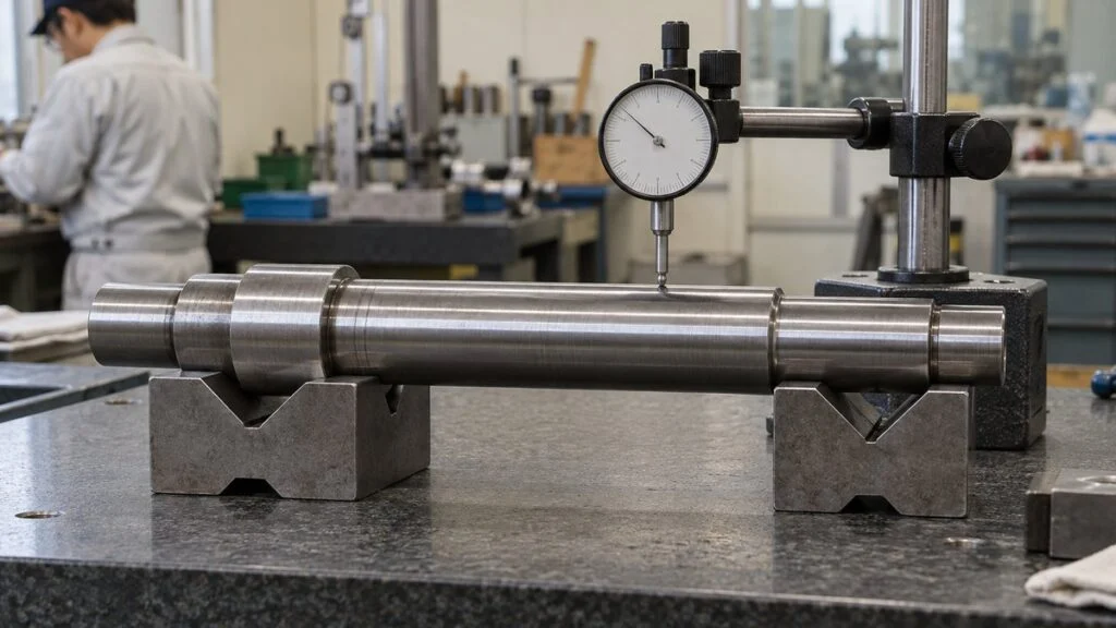
A common datum is a single datum established from two datum features. The classic case is a shaft supported by bearings at both ends. The shaft actually rotates on its two bearing journals, so the common axis of both journals matches the function better than either journal alone. On the drawing, the two letters are joined with a hyphen, such as "A-B," in a single compartment of the tolerance frame (JIS B 0021:1998). ASME Y14.5 uses the same hyphenated form.
There is no precedence between the two features of a common datum. For a simple shop-floor check, AIST training material shows the part supported on V-blocks on a surface plate with a dial indicator, as in the photo above.
Datum Targets: Use Only Part of a Wavy Surface
As-cast or as-forged surfaces (called kurokawa, 黒皮, "black skin," in Japan) and large sheet metal parts can deviate far from an ideal plane over their full area. JIS B 0022 recognizes this and defines datum targets: points, lines, or limited areas on the surface that alone are used to establish the datum.
A datum target is shown in a circle divided horizontally, with the datum letter and a number (A1, A2, and so on) in the lower half. A point target is marked with an ×, a line target with two × marks joined by a thin solid line, and an area target with hatching. ASME uses the same divided-circle layout. According to Keyence, defining only the minimum necessary areas improves repeatability and reproducibility. Target locations are given with theoretically exact dimensions (TEDs, called basic dimensions in ASME): boxed dimensions with no tolerance of their own.
Matching the targets to the machining setup pays off. If the first operation supports the cast surface on three fixture pins, the same three points can reproduce the datum from roughing through finishing and inspection. Newer ISO editions add concepts such as movable datum targets, and ASME Y14.5 also has a movable datum target symbol, but JIS does not yet define them.
Five Reasons Datum Measurements Disagree
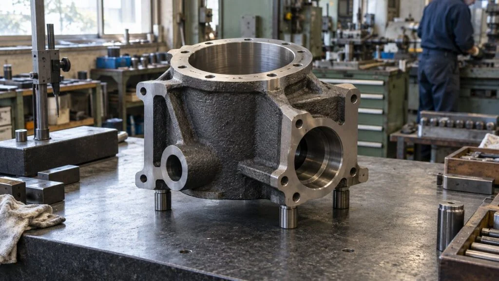
Even with a correct datum callout, values will not agree if each person or machine builds the reference differently. The classic case is "passed at the supplier, rejected at the customer's incoming inspection." Most of these disagreements come from different ways of reproducing the datum, not from the part itself.
Before blaming the part, check that both sides build the datum the same way.
Classified by the MONOSCOPE editors from Keyence and Mitutoyo technical material and a measurement case study by the Nagano Prefecture Industrial Technology Center.
1. Different Simulated Datum Features: Surface Plate, V-Block, 3-Point Support
When a datum plane is established on a surface plate, setting the bottom face directly on the plate makes the plate itself the simulated datum feature. For axes, JIS B 0022 establishes the datum from the axis of the largest inscribed cylinder for a hole and the smallest circumscribed cylinder for a shaft. Keyence's guide shows this reproduced with a precision pin (such as a mandrel) in a hole, or a precision bore around a shaft. When the datum feature is convex and rocks, JIS B 0022 describes stabilizing it on two supports for a line or three supports for a surface.
Setting a part directly on the plate and setting it on three support pins can put the datum in different places on the same part. Specify the method in a drawing note or in the inspection standard (検査規格書, kensa kikakusho).
2. Different Fitting Methods: Contact vs. Least Squares
On a surface plate, the highest points of the bottom face touch the plate, and that contact defines the datum. JIS B 0022 takes the same approach: the datum is set in contact with the datum feature so that the maximum gap is as small as possible.
A coordinate measuring machine (CMM), by contrast, usually calculates planes and circles by least squares when it has many points, according to Keyence. A least-squares plane runs through the "average" of the bumps, so its position and tilt differ slightly from a plane resting on the high points. The worse the flatness of the datum face, the more this difference shows up in the results.
Planes are not the only case. Mitutoyo lists four ways to evaluate roundness (least-squares center, minimum zone center, minimum circumscribed circle center, and maximum inscribed circle center) and notes that each gives a different value. When you build datums on a CMM, record the fitting method in the measurement report so you can trace the cause when results differ.
3. Number and Spread of Measurement Points
Mitutoyo's CMM guide notes that changing the number of points by just one, or moving them, changes how uncertainty propagates. If the datum face is measured with a few points in a small area, the calculated tilt of the plane wobbles, and small changes in that tilt cause large changes in the measured position of holes located away from the measured area.
Spread the points over as much of the datum face as possible and fix their locations in the part program. If each operator picks points differently, that alone is a major source of variation.
4. Waviness, Warp, and Temperature
A researcher at the Nagano Prefecture Industrial Technology Center reported a case in which the bottom of a 225 × 140 × 18 mm steel plate was set directly on a surface plate as datum A. The parallelism of the top face was measured two ways. Moving the indicator over the fixed part gave 18 µm (about 0.0007 in), while moving the part under a fixed indicator gave 12 µm (about 0.0005 in). The same part gave different results depending on the method.
The same report notes that if the surface plate is colder than the part, the area near the contact face cools, the part bows upward in the middle, and an accurate simulated datum plane can no longer be formed. Let parts soak to temperature before measuring, and wear gloves so body heat does not transfer.
Surface plates have their own flatness tolerances by grade. The report cites JIS B 7513 values for a 630 × 400 mm plate: 5.0 µm for grade 0, 10 µm for grade 1, and 20 µm for grade 2. Regular calibration of plates and instruments is a precondition; see our guide to JCSS calibration certificates, intervals, and records.
5. Misread Precedence
The last cause is reading the drawing differently. The frame says A | B | C, but the inspector sets face B on the plate first because it is easier. Or a common datum A-B is built from only one bearing journal. As Figure 5 shows, changing the order changes the part's orientation and therefore the result.
For critical parts, document in the inspection standard which face goes on which tool, in which order, with drawings or photos. Then the method stays the same when inspectors change.
Worked Example: Poor vs. Good Datum Callouts on a Bracket
Here is how these ideas apply to a fictional part: a 120 × 70 × 10 mm plate bracket with two Ø10 mounting holes. The bottom face sits on the machine base, the left side bears against a stop, and the front side (the lower edge in the top view of Figure 8) sets the front-to-back position before the part is bolted down.
The contact order in assembly (bottom → left side → front side) becomes A, B, C. Hole locations are set by TEDs and a position tolerance.
Part shape, dimensions, and tolerance values are fictional examples created by the MONOSCOPE editors, not real products or recommended values. Symbols follow JIS B 0021:1998.
The tricky part is that each poor callout looks valid. Making the top face datum A is legal GD&T notation, but it does not guarantee the accuracy of the bottom face that actually seats in assembly. Which face you choose affects quality more than how neatly the symbols are drawn.
The good callout puts flatness on the primary datum face. As noted above, JIS B 0022 recommends form tolerances on datum features. Controlling the datum face first keeps the part stable on the plate and reduces measurement variation. Set the actual tolerance values from process capability and the mating parts.
Datum Checklist: Before You Release, Machine, or Inspect
A datum scheme only works when machining and inspection can reproduce it the same way. AIST's GD&T training material lists three checks when adding geometric tolerances: can it be machined, can it be inspected, and is the datum stable? Our checklist builds on that:
- Primary, secondary, and tertiary order matches the contact order in assembly
- Each datum face sits stably on a plate or fixture; form tolerances such as flatness added where needed
- Each datum triangle is placed as intended: on the surface, or in line with a dimension for an axis or median plane
- Datum targets define the contact areas on wavy or as-cast faces
- Machining and inspection use the same datum faces; if not, the difference has been discussed with machining
- For CMM inspection, the fitting method and point layout are agreed with the inspector
- The drawing or contract states which standard and edition governs (JIS, ISO, or ASME Y14.5)
The last few items are easiest to settle at the design review, by having machining and inspection look at the drawing. For how Japanese companies structure design reviews and quality planning, see our quality assurance process at Japanese plants.
Questions to Ask the Japanese Side
If you receive a Japanese drawing and the datum setup is not obvious, ask in writing before you machine or inspect:
- Is the drawing interpreted under JIS (B 0021/B 0022), ISO, or ASME Y14.5? Which edition?
- How should each datum be simulated: directly on a surface plate, on three support pins, in a V-block, or on a mandrel?
- For CMM inspection, which fitting method do you use for datum planes and axes (tangent/contact or least squares)?
- Do you have an inspection standard (kensa kikakusho) or fixture drawing that shows the datum setup? Can you share it in English?
- Where a datum triangle sits near a dimension line, is the datum the surface or the axis/median plane?
- For common datum A-B, should both journals be supported together?
A short email you can adapt (the drawing number and details are fictional):
Subject: Datum setup for drawing XYZ-5678 Rev. A
Hello [Name],
Before we start first-article inspection of XYZ-5678 Rev. A, could you confirm the following?
1. Should the drawing be interpreted under JIS B 0021/B 0022 or ASME Y14.5?
2. Datum A (bottom face): should the part sit directly on the surface plate, or on three support pins? If pins, where?
3. On your CMM, do you fit datum A as a tangent plane or a least-squares plane?
4. For the position tolerance Ø0.1 | A | B | C, please confirm the contact order is A, then B, then C.If you have an inspection standard or fixture drawing for this part, we would appreciate a copy.
Best regards,
[Your name]
Limits of This Guide
- This guide follows JIS B 0022:1984 and JIS B 0021:1998. ISO 5459:2024 and ASME Y14.5-2018 add concepts and rules not covered here, such as datum feature modifiers and detailed fitting rules.
- The ASME comparisons are limited to terms and basic conventions. For ASME-specific requirements, refer to the standard itself.
- Older Japanese drawings may use obsolete indication methods. Company drawing standards can also add their own rules.
- All part shapes, dimensions, and tolerance values in the figures are fictional. Set real values from function and process capability, and agree on them with the Japanese side.
FAQ
How do you choose primary, secondary, and tertiary datums?
Follow the assembly order. The face that seats first on the mating part is primary, the next face to make contact is secondary, and the face that finally fixes location or stops rotation is tertiary. Then check that each face can be supported steadily and that machining and inspection can use it.
Do you always need three datums?
No. The number of datums depends on which degrees of freedom must be fixed to evaluate the tolerance. To locate holes with a position tolerance, the usual approach is a three-plane datum system that fixes all six degrees of freedom.
Is the datum triangle filled or open?
Under JIS B 0021:1998, either is correct and the meaning is the same. What changes the meaning is placement: offset on the surface makes the surface the datum, while in line with a dimension line makes the axis or median plane the datum.
Why don't CMM and surface plate results match?
A CMM usually fits a least-squares plane through the measured points, while a surface plate contacts the high points of the face. Record which method built the datum in the measurement report so you can trace differences.
Are JIS datums the same as ASME datums?
The concepts are closely comparable: datum features, three-plane datum systems (datum reference frames), precedence from left to right, common datums, and datum targets. The standards and editions differ, though, and so do some defaults, such as ASME's Rule #1. Confirm which standard governs each drawing.
Sources
- JIS B 0022:1984: JSA Webdesk, "Datums for geometrical tolerancing" (Japanese)
- JIS B 0021:1998: JSA Webdesk, "GPS – Geometrical tolerancing" (Japanese)
- JIS B 0024:2019: JSA Webdesk, "GPS – Fundamentals" (Japanese)
- Current ISO editions: ISO 5459:2024 Datums and datum systems, ISO 1101:2017 Geometrical tolerancing
- Current ASME edition: ASME, Y14.5 Dimensioning and Tolerancing
- Datum reference frame and precedence in ASME practice: GD&T Basics, "Datum Reference Frame", "Datum"
- ASME datum target symbol: PTC Creo Elements/Direct GD&T glossary
- Datum basics, symbols, common datums, datum targets: Keyence, "What is a datum?", "Datum types", "Common datums and datum systems", "Datum targets" (Japanese)
- CMMs and least squares: Keyence, "Coordinate measuring machines" (Japanese)
- Measurement strategy and uncertainty: Mitutoyo, CMM basics, Mitutoyo, roundness tester basics (Japanese)
- Surface plate case study: Nagano Prefecture Industrial Technology Center, "Parallelism measurement of two planes on a surface plate," Research Report No. 17 (2022) (Japanese)
- Precedence and assembly order: Nikkei xTECH (Nikkei Monozukuri), "Basic GD&T, Part 2: Three-plane datum systems" (2007) (Japanese)
- Function-based datum selection: MONOist, "Understanding datums" (2009), page 3, area and waviness (Japanese)
- Datum precedence and common datums: Kabuku Connect, GD&T series part 3, OPEO, "Datum targets" (Japanese)
- Precedence and inspection results: Cybernet Systems, GD&T basics (Japanese)
- GD&T checks and simple common-datum inspection: AIST, "Basics of geometrical tolerancing" (Japanese)
Original article in JapaneseThis guide is adapted from a MONOSCOPE article written for readers in Japan: データムの取り方|幾何公差の基準の決め方と測定でずれる原因
About the editor
 MONOSCOPE EditorFOUNDER & EDITOR
Spent about ten years at a plant equipment maker and a plant engineering company, proposing, designing, and commissioning equipment, then moved into web marketing. Now a web consultant for B2B manufacturers, helping them explain their products and technology. Licensed in Japan as an Energy Manager and a Third-Class Chief Electrical Engineer.
Has run an engineering blog since 2017 (500+ articles) and a Japanese YouTube channel with about 20,000 subscribers. Each English guide is written from the Japanese shop-floor point of view and checked against the cited standards.