How to Read Japanese Engineering Drawings (JIS B 0001)
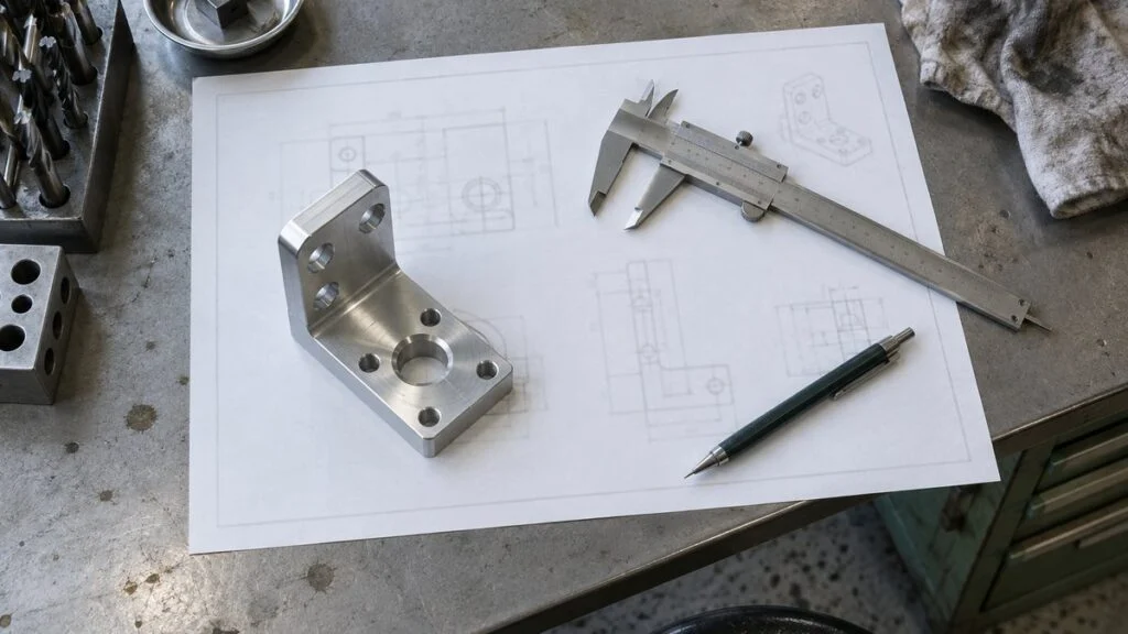
A Japanese customer or supplier has just sent you a drawing. The views look familiar, but the title block is in Japanese, the dimensions carry no units, and some hole callouts end in katakana such as キリ. Where do you start?
Start with the good news: Japanese mechanical drawings follow the Japanese Industrial Standards (JIS), mainly JIS B 0001 (Technical drawings for mechanical engineering), and JIS uses third-angle projection by default, the same as US practice. Most symbols (Ø, R, counterbore, depth) are the same ones you see on ISO and ASME drawings. What trips people up is a short list of Japan-specific items: the Japanese words in the title block, the "C" chamfer notation, katakana process notes, and blanket notes written in Japanese.
This guide walks through a Japanese drawing in the order an engineer in Japan would read it: title block, views, line types, section views, dimension symbols, hole and thread callouts, and tolerances. It ends with a reading checklist and a list of questions to send back to the Japanese side.
Contents
- Start With the Title Block
- Is Japan First Angle or Third Angle?
- Line Types and What They Mean
- Section Views and Hatching
- Dimension Symbols: Ø, R, C, □, and More
- Hole and Thread Callouts: Kiri, Zaguri, M10
- Tolerances, Fits, and Surface Finish
- A Reading Order That Catches the Big Mistakes
- Checklist: Before You Quote, Machine, or Inspect
- Questions to Send the Japanese Side
- Limits of This Guide
- FAQ
- Sources
Start With the Title Block
Before you look at a single view, read the title block (表題欄, hyodairan) in the lower-right corner. It tells you what the part is, the scale, the projection method, and which revision you are holding. Those are the assumptions you need before any dimension makes sense.
Inside the border, a Japanese drawing typically has a view area, a notes area, a revision block, and the title block. Layouts vary from company to company, but the lower-right title block is common to most of them.
Check the title block in the lower right before you read the views.
Layouts and field names vary by company. JIS B 0001 lists the items a title block should contain.
JIS B 0001 lists items for the title block such as the drawing number, drawing title, company name, the signature of the responsible person, the date the drawing was made, the scale, and the projection method. In practice, most companies also add the material, surface treatment, and heat treatment.
Japanese Title Block Terms in English
The table below lists the labels you are most likely to see. Exact wording varies by company, so treat it as a starting point.
| Japanese | Romaji | English | What to check |
|---|---|---|---|
| 図番 / 図面番号 | zuban / zumen bango | Drawing number | Matches the PO and the quote |
| 品名 / 図名 | hinmei / zumei | Part name / drawing title | Matches the part you were asked to make or inspect |
| 材質 | zaishitsu | Material | JIS grade (e.g., SUS304, A5052); find the local equivalent before you buy stock |
| 数量 | suryo | Quantity | Whether it means per assembly or the order quantity |
| 表面処理 | hyomen shori | Surface treatment (plating, anodizing, coating) | Treatment type and thickness, if given |
| 熱処理 | netsu shori | Heat treatment | Process and target hardness |
| 尺度 | shakudo | Scale | For reference only; never measure the print |
| 投影法 | toeiho | Projection method | Third angle (第三角法, dai-san-kakuho) or first angle (第一角法, dai-ikkaku-ho) |
| 単位 | tan'i | Units | Normally mm |
| 普通公差 | futsu kosa | General tolerances | Standard and class, e.g., JIS B 0405-m |
| 改訂 / 改訂記号 | kaitei / kaitei kigo | Revision / revision mark | Latest revision; what changed |
| 設計 / 製図 / 検図 / 承認 | sekkei / seizu / kenzu / shonin | Designed / drawn / checked / approved | All signatures or stamps present |
| 日付 | hizuke | Date | Often written year/month/day |
| 注記 | chuki | Notes | Blanket instructions that apply to the whole part |
For the material box, Japanese drawings use JIS grade names. If you see SUS304 or SUS316L, see our guide to SUS304, SUS316, and SUS430 and their AISI/ASTM equivalents.
Related: A5052 Equivalent: JIS Aluminum Designations vs. AA/ASTM
Check the Revision First
The revision mark is easy to overlook. A drawing can keep the same number while its dimensions change from one revision to the next. Confirm that you have the latest revision before you quote, machine, or inspect; it is the simplest way to avoid making parts to an outdated drawing.
Keep in mind that a drawing is how the designer communicates intent. The dimensions and symbols were chosen with the part's function and assembly in mind, so when something looks odd, ask instead of assuming it is a mistake.
Scale and Numbers Without Units
A scale of "1:2" means the part is drawn at half its actual size. The numbers on the drawing are always actual sizes, whatever the scale, so never take dimensions by measuring the print.
You will also notice that the dimensions have no "mm." Under JIS B 0001, lengths are normally given in millimeters without a unit symbol, so "50" means 50 mm (about 1.97 in). Angles are generally given in degrees.
Is Japan First Angle or Third Angle?
Japan uses third-angle projection. JIS B 0001 states that views are drawn in third-angle projection, the same default as ASME practice in the US. Europe and India commonly use first-angle projection, so if you work with suppliers in several countries, check every drawing.
In third-angle projection, the front view is the reference. The top view goes above it and the right-side view goes to its right. In other words, each view sits on the same side from which you look at the part.
A stepped block with one vertical through-hole, seen from three directions.
The light dotted lines only show how the views line up (equal width and height). They do not appear on a real drawing.
The Front View Shows the Most Information
The front view is not necessarily the side you would call the "front" of the part. JIS B 0001 says the view that shows the part most clearly becomes the front view (principal view).
On a machining drawing, the part is usually drawn in the orientation it sits in for most of the machining operations, and laid out horizontally unless there is a reason not to. A turned shaft, for example, is normally drawn lying on its side.
Read the Views Together
You cannot see the shape from any one view on its own. The front and top views share the same width, and the front and right-side views share the same height, so trace each line from one view to the matching position in the next.
In Figure 2, the circle in the top view lines up with the dashed lines in the front and right-side views, so it is a hole that runs all the way through the block. If the shape is not obvious, a quick 3D sketch on paper helps.
It is now common for Japanese companies to create 2D drawings from 3D CAD models, and the model may come with the drawing. Ask which one governs if the two disagree.
How to Tell First Angle From Third Angle
In first-angle projection, the views are flipped: the top view goes below the front view and the right-side view goes to the left. JIS allows first angle only when the third-angle layout does not fit on the sheet or would make the drawing harder to understand, and the first-angle symbol must then be shown in or near the title block.
Same part, opposite layout.
Check the projection symbol (a truncated cone shown from two directions) in or near the title block.
Mixing up the projection produces a mirror-image part, with holes and steps on the wrong side. Check the projection symbol on every drawing, especially when you handle drawings from several countries or old drawings.
Line Types and What They Mean
Every line on a Japanese drawing has a defined meaning. JIS B 0001 assigns a use to each combination of line type (continuous, dashed, chain) and thickness, so the line itself tells you whether it is an outline, a hidden feature, or a dimension.
JIS uses three thicknesses (thin, thick, and extra thick), generally in a 1:2:4 ratio. As a first pass, remember that thick continuous lines are visible outlines and thin lines carry supporting information.
The line type and thickness tell you what each line represents.
A selection of common uses from JIS B 0001:2019. Hidden lines may be either thin or thick dashed lines.
Beginners often confuse dashed lines with chain lines. A dashed line is a row of short dashes of equal length; a chain line alternates long dashes with dots. A dashed line shows a hidden shape; a chain line shows a center position, not a shape.
Phantom lines are also easy to misread. Whatever is drawn in double-dot chain lines is not part of the item on this drawing. It shows a mating part or the position a moving part reaches, so do not machine it.
Section Views and Hatching
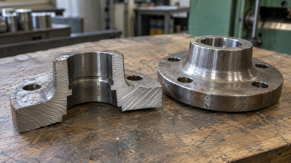
When a part has holes and grooves inside, an outside view fills up with overlapping hidden lines. A section view solves this by cutting the part on an imaginary plane and showing the internal shape exactly as it appears at the cut.
The cut surface may be hatched with evenly spaced, thin diagonal lines. Hatching means solid material; no hatching means empty space. A cutting plane line in another view, labeled with letters such as "A-A," shows where the cut was made.
Types of Section Views
JIS B 0001 describes several section views. Drafters choose the one that shows the needed internal detail most simply:
- Full section: the whole part is cut along the plane that best shows its basic shape
- Half section: for a symmetrical part, half is drawn as an outside view and half as a section
- Partial (broken-out) section: only the area of interest is cut, bounded by a break line
- Revolved section: the cross-section of an arm or rib is rotated 90° and drawn on the view
- Combined section: several cutting planes are joined into one section view
Half sections are common on axially symmetric flanges and covers. With the center line as the dividing line, one view shows both the outside shape and the internal steps.
Parts That Are Never Sectioned Lengthwise
On assembly drawings, shafts and bolts often appear unsectioned inside a section view. This is not an omission. JIS B 0001 says shafts, pins, bolts, nuts, washers, keys, steel balls, and similar parts are not cut lengthwise.
Cutting a solid part like a shaft or bolt adds no new information. Ribs, arms, and gear teeth are not cut lengthwise either, because sectioning them would make the shape harder to understand. If one part in a section view has no hatching, this rule is the likely reason.
Dimension Symbols: Ø, R, C, □, and More
A number alone does not tell you whether it is a diameter or a radius. The symbol in front of the number does: it identifies what kind of dimension you are looking at. JIS calls these dimension symbols (寸法補助記号, sunpo hojo kigo).
The symbol before the number tells you what the dimension measures.
Selected from the JIS B 0001:2019 dimension symbols. The counterbore, countersink, and depth symbols were added in the 2010 edition; older drawings may spell them out in Japanese instead.
The three you will see most are φ, R, and C. Japanese drawings often write the diameter symbol as φ (the Greek letter phi); it means the same as Ø on ASME and ISO drawings. R is the radius of a round or arc. C is the size of a 45° chamfer: C1 means a 45° chamfer 1 mm from the corner. The C notation can confuse shops outside Japan, because drawings made to ASME Y14.5 normally write the same chamfer as 1 X 45°.
The notes often include a blanket instruction such as 指示なき角部はC0.5 (shiji naki kakubu wa C0.5), which means "chamfer all unspecified edges C0.5." It applies even where an edge has no symbol, so always read the notes along with the views.
You will see φ both inside circular views and on features that look like rectangles from the side. A φ on a rectangular-looking feature means that feature is a cylinder, which lets the drafter leave out a view.
Hole and Thread Callouts: Kiri, Zaguri, M10
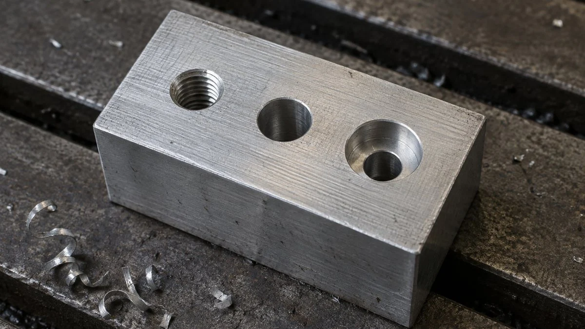
Hole callouts pack a lot of information into a small space, which makes them easy to misread. One leader line can carry the number of holes, the diameter, the process, and the counterbore diameter and depth. Split the callout into pieces and read it from left to right.
Split one line into its parts and you are less likely to misread it.
Values are examples for illustration. Older drawings may write the same callout in Japanese text, e.g., 4-φ9キリ φ14深ザグリ深さ8.6.
Katakana Process Notes: Kiri, Reamer, Zaguri
The katakana after a hole diameter is a short process note. JIS B 0001 defines these simplified notes:
| On the drawing | Romaji | Meaning |
|---|---|---|
| キリ | kiri | Drilled |
| リーマ | rima | Reamed |
| 打ヌキ | uchinuki | Punched (press-pierced) |
| イヌキ | inuki | Cored (as cast) |
A drilled hole (kiri) is not very precise. A reamed hole is drilled and then finished with a reamer for accurate size and a smoother bore, so designers specify it where a fit matters, such as a dowel pin hole.
A counterbore (ザグリ, zaguri) is a stepped recess that gives a bolt head a flat seat or keeps it from sticking out above the surface. A deep counterbore (深ザグリ, fuka-zaguri) is cut deep enough to sink the whole bolt head, and a countersink (皿ザグリ, sara-zaguri) is a conical recess for flat-head screws.
Thread Callouts: M10 vs. M10×1.25
Under JIS B 0123 (Designation of screw threads), a metric thread is written as "M," the nominal diameter, "×," and the pitch. For coarse threads, each diameter has only one pitch, so the pitch is usually left out.
An M10 coarse thread has a 1.5 mm pitch, so the drawing simply says "M10." "M10×1.25" means a fine thread. The two look almost identical, but an M10 bolt will not fit an M10×1.25 tapped hole, so check the pitch when you buy fasteners or assemble.
You may also see "LH" for a left-hand thread and tolerance classes such as "6H" or "6g": uppercase for internal threads, lowercase for external threads. The class is often omitted; in that case, the company standard or the customer's specification applies.
Tolerances, Fits, and Surface Finish
Once you know the shape and size, the next question is how accurate the part has to be. The drawing states its accuracy requirements as symbols and numbers: how far a dimension may vary, how a hole and shaft fit together, and how smooth a surface must be.
Size tolerance, fit, and surface texture each have their own notation.
Surface texture symbols per JIS B 0031. Values such as Ra are written under the horizontal bar of the symbol or nearby.
Size Tolerances and General Tolerances
"50±0.1" means any size from 49.9 mm to 50.1 mm passes. Not every dimension carries a tolerance. Dimensions without one fall under the general tolerances (普通公差, futsu kosa).
JIS B 0001 says the standard number and tolerance class should be stated once, in or near the title block. For what "JIS B 0405-m" means in actual numbers and how it compares with ASME practice, see our JIS B 0405 general tolerance chart.
Geometric tolerances (flatness, perpendicularity, position, and so on) appear in feature control frames. They have their own set of rules and are outside the scope of this guide.
Related: Datum Selection in GD&T: JIS vs ASME on Japanese Drawings
Fits: H7/g6
A letter and number after a size, as in "φ10H7," is a fit tolerance code under JIS B 0401, the Japanese counterpart of ISO 286. Uppercase letters are holes, lowercase letters are shafts, and the number is the tolerance grade; the larger the number, the wider the tolerance.
A φ10H7 hole, for example, must finish between 10.000 mm and 10.015 mm. A φ10g6 shaft must finish between 9.986 mm and 9.995 mm. Combined as "H7/g6," they form a widely used clearance fit: the shaft slides in and leaves a small gap.
Surface Texture: Ra
The check-mark symbol specifies surface texture (roughness and lay). JIS B 0031 uses three variants: the basic symbol, the symbol with a bar (material removal required), and the symbol with a circle (no material removal). "Ra 1.6" next to the symbol means an arithmetical mean roughness of 1.6 µm (about 63 µin).
The symbol can also carry the process (such as grinding) and the direction of the lay. Designers tend to specify smaller values on functional surfaces such as sliding surfaces and seal faces. If you see the older triangle marks (▽▽▽) instead, see our guide to JIS surface roughness: Ra, Rz, and triangle finish symbols. Plating, painting, and heat treatment usually appear in the notes.
Related: JIS Plating Callouts (Ep-Fe/Zn8/CM2) and ASTM Equivalents
A Reading Order That Catches the Big Mistakes
In short, read from the whole to the details, and from shape to accuracy. If you start by picking off individual dimensions, you can miss the big errors, such as a mixed-up projection or an outdated revision.
Work from the whole to the details, and from shape to accuracy.
The focus differs for machining, inspection, and purchasing, but steps 01–03 are the same for everyone.
Each role tends to focus on different parts of the drawing:
- Machining: processes and accuracy requirements
- Inspection: tolerances, surface texture, and what to measure where
- Purchasing: material, surface treatment, thread type, and other specifications that affect what you buy
For inspection, the drawing tolerances become the acceptance criteria for incoming and outgoing inspection.
The last step matters as much as the first. If a feature can be read two ways, or you do not know what a symbol means, guessing can lead to scrapped parts. Asking the designer before you machine is usually the fastest and safest route.
Checklist: Before You Quote, Machine, or Inspect
- Drawing number and revision match the purchase order or request for quote
- Projection symbol checked (third angle is the JIS default)
- Units confirmed as millimeters
- Material (材質) translated to a grade you can buy, and the substitution approved in writing
- Surface treatment (表面処理) and heat treatment (熱処理), including thickness or hardness
- General tolerance standard and class (e.g., JIS B 0405-m)
- Blanket notes translated, especially chamfer and edge instructions such as C0.5
- Hole callouts split into count, diameter, process, counterbore, and depth
- Thread pitch confirmed (M10 coarse vs. M10×1.25 fine) and thread class, if given
- Fit codes (H7, g6) converted to limits from the JIS B 0401 / ISO 286 tables
- Surface texture symbols and values, including any old triangle marks
- 3D model status: reference only, or does it govern where the drawing is silent?
Questions to Send the Japanese Side
Japanese drawings may refer to company standards that you do not have. If something is unclear, ask in writing before you start. Useful questions:
- Is this the latest revision? What changed from the previous revision?
- Which general tolerance standard and class apply, if the title block does not say?
- May we use a local material grade equivalent to the JIS grade on the drawing? Which certificate do you need?
- For unspecified chamfers and edges, what is acceptable?
- Which company standards (for threads, surface treatment, marking) does the drawing refer to, and can you send them in English?
- If the 3D model and the drawing disagree, which one governs?
A short email template you can adapt (the drawing number and items are fictional):
Subject: Questions on drawing ABC-1234 Rev. B

Hello [Name],

Thank you for sending drawing ABC-1234 Rev. B. Before we quote, could you confirm the following?

1. Is Rev. B the latest revision?
2. The title block does not show a general tolerance. Should we apply JIS B 0405-m?
3. Material is SUS304. May we use ASTM A240 Type 304 plate with a mill test certificate?
4. Note 2 says "C0.5 for unspecified edges." Does this also apply to the internal edges of the φ9 holes?
5. Hole callout 4×φ9 キリ ⌴φ14 ↧8.6: please confirm the counterbore depth of 8.6 mm.

Best regards,
[Your name]
Limits of This Guide
- This guide follows JIS B 0001:2019. Older drawings may use earlier notations, such as hole notes written out in Japanese.
- Title block layouts and field names vary by company. The term table lists common labels, not a standard set.
- Company standards and customer specifications can differ from the general rules here. If they seem to conflict, ask the customer which takes precedence.
- Geometric tolerancing and welding symbols are outside the scope of this guide.
- Material equivalents, tolerance values, and fits should be confirmed against the current standards and agreed with the Japanese side before you produce parts.
FAQ
Do Japanese drawings use first-angle or third-angle projection?
Third angle. JIS B 0001 makes third-angle projection the default, the same as ASME practice in the US. First angle is allowed only when space or clarity requires it, and the first-angle symbol must then appear in or near the title block.
What units do Japanese engineering drawings use?
Millimeters. JIS B 0001 says lengths are normally given in millimeters without the unit symbol, so "50" means 50 mm. Angles are generally in degrees.
What does C1 mean on a Japanese drawing?
A 45° chamfer, 1 mm from the corner. On a drawing made to ASME Y14.5, the same chamfer is usually written as 1 X 45°.
What does キリ (kiri) mean on a Japanese drawing?
It means the hole is drilled. Other katakana process notes are リーマ (reamed), 打ヌキ (punched), and イヌキ (cored as cast).
What is the difference between M10 and M10×1.25?
M10 is a coarse thread with a 1.5 mm pitch; the pitch is left out because coarse threads have only one pitch per diameter. M10×1.25 is a fine thread with a 1.25 mm pitch. The two are not interchangeable.
Sources
- Projection, title block, units, line types, section views, dimension symbols, process notes, general tolerance indication: JIS B 0001:2019, Technical drawings for mechanical engineering (kikakurui.com, Japanese)
- Thread designation: JIS B 0123:1999, Designation of screw threads (kikakurui.com, Japanese)
- Metric coarse and fine thread pitches: Neji No1.com, metric thread (coarse and fine) table (Japanese)
- Surface texture symbols: JIS B 0031:2003, Indication of surface texture in technical product documentation (kikakurui.com, Japanese)
- Fit codes (uppercase for holes, lowercase for shafts): MONO Juku, "What is the H7 fit tolerance?" (Japanese)
- H7 and g6 limit deviations (JIS B 0401): Tsubakimoto Chain, fit tolerance and limit deviation table (Japanese)
- Counterbore, countersink, and depth symbols added in 2010: Otsuka Shokai, key changes in the 2010 JIS drafting standard (Japanese)
- First-angle and third-angle use by region: MFG Hack (Kanto Seisakusho), basics of projection and three-view drawings (Japanese); Xometry Pro, first angle vs. third angle projection
- JIS B 0401-1:2016 based on ISO 286-1:2010: AFNOR catalog, JIS B 0401-1
- Chamfer callouts in ASME Y14.5 practice: Eng-Tips, "Chamfer call out"; SOLIDWORKS Help, chamfer dimensions
Original article in JapaneseThis guide is adapted from a MONOSCOPE article written for readers in Japan: 機械図面の読み方でつまずく疑問8選|三面図・線・記号を初心者向けに
About the editor
 MONOSCOPE EditorFOUNDER & EDITOR
Spent about ten years at a plant equipment maker and a plant engineering company, proposing, designing, and commissioning equipment, then moved into web marketing. Now a web consultant for B2B manufacturers, helping them explain their products and technology. Licensed in Japan as an Energy Manager and a Third-Class Chief Electrical Engineer.
Has run an engineering blog since 2017 (500+ articles) and a Japanese YouTube channel with about 20,000 subscribers. Each English guide is written from the Japanese shop-floor point of view and checked against the cited standards.