Direct vs Reverse Acting Control Valves: NO/NC, FO/FC/FL
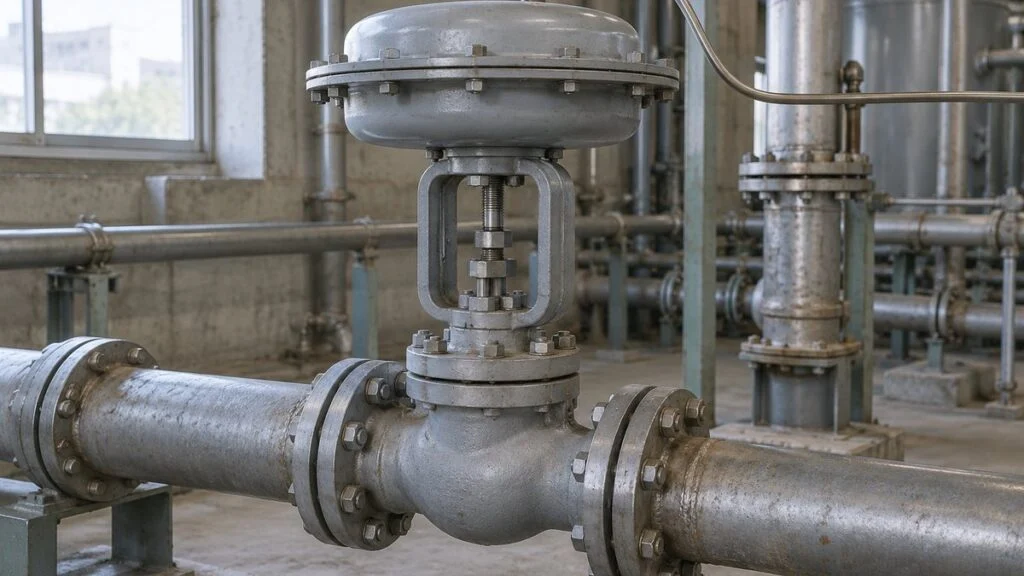
Picture a typical case: a control valve datasheet from a Japanese EPC contractor or valve maker lists the actuator as 正作動 (sei-sado), the air action as 空気開, and the fail position as 失気時閉. The P&ID next to it shows "FC" under the valve symbol, and the I/O list says "NC." Your loop drawing asks whether the controller is direct or reverse acting. Are these all saying the same thing?
Not quite. "Direct" and "reverse" describe which way one device's output moves when its input increases, and that question can be asked of the actuator, the valve body, the positioner, or the controller, each with a different answer. NO and NC (normally open, normally closed) describe a different thing: the position a product takes in its defined de-energized or unpressurized state. Fail-open (FO), fail-closed (FC), and fail-last (FL) describe where the valve ends up after a specific failure.
This guide maps the Japanese spec terms to their English equivalents, explains each level of "direct vs. reverse," separates air failure from signal loss and power loss, and ends with a checklist and questions to send to the Japanese side. It focuses on pneumatic, spring-return control valves.
Contents
- Quick Reference: Japanese Valve Action Terms in English
- Four Places "Direct" and "Reverse" Can Apply
- Air Failure, Signal Loss, and Power Loss Are Different Failures
- Choosing the Fail Position: Start From the Process
- Write the 4–20 mA Endpoints on the Spec
- Changing the Action and Testing It at Commissioning
- Checklist: Valve Action Items on a Japanese Datasheet
- Where This Guide Does Not Apply
- FAQ
- Sources
Quick Reference: Japanese Valve Action Terms in English
Use this table to read a Japanese datasheet, then confirm each item against the maker's instruction manual. Japanese makers do not all use the same naming, and the same word can apply to different devices.
| Japanese term (romaji) | Closest English term | What it describes |
|---|---|---|
| 正動作 / 逆動作 (sei-dosa / gyaku-dosa) | Direct action / reverse action | Used for the controller in manuals such as Yokogawa's: output rises (direct) or falls (reverse) as the measured value rises |
| 正作動 / 逆作動 (sei-sado / gyaku-sado) | Direct-acting / reverse-acting | Azbil manuals use it for the actuator (which way air pressure moves the stem). Some products use it for the whole valve (signal to close / signal to open) |
| 空気開 | Air to open (ATO) | Air pressure opens the valve. On a spring-return valve, it usually goes with fail closed |
| 空気閉 | Air to close (ATC) | Air pressure closes the valve. On a spring-return valve, it usually goes with fail open |
| 失気 (shikki) | Loss of air / air failure | The actuating air supply is lost |
| 失気時閉 / 失気時開 | Fail closed (FC) / fail open (FO) on air failure | Position after loss of air, with the failure condition stated |
| 失気時保持 or similar wording (varies by maker) | Fail last / fail locked (FL) | Holds position after loss of air; needs added equipment such as a lock-up valve |
| NO / NC (ノーマルオープン / ノーマルクローズ) | Normally open / normally closed | Position in the product's defined de-energized or unpressurized state, not the position during normal operation |
| 押下げ閉 / 押下げ開 (push-to-close is also called 正栓) | Push-down-to-close / push-down-to-open body | How the plug responds when the stem moves down |
| 正出力 / 逆出力 (positioner) | Direct / reverse output | Positioner output air pressure rises or falls as the input current rises |
| 信号断 / 停電 | Signal loss / power loss | Separate failure modes from air failure; check each one |
| 単動 / 複動 (tando / fukudo) | Single-acting (spring return) / double-acting | Whether a spring returns the actuator when air is lost |
On P&IDs that follow ISA-5.1 conventions, the fail position commonly appears as FO, FC, FL, or FI (fail indeterminate) next to the valve symbol. Japanese drawings often use the same letters, but check the drawing legend on each project. How to read P&ID instrument symbols: ISA-5.1 vs JIS covers the symbol side.
Four Places "Direct" and "Reverse" Can Apply
A pneumatic control loop has a chain of devices, and each one has its own input and output. If "direct acting" is used for the whole chain at once, different meanings get mixed together.
At the whole-valve level, some products call a valve that closes on increasing signal direct acting and one that opens on increasing signal reverse acting. Azbil's electric control valve specifications express this as Signal to Close and Signal to Open.
Figure 1: Separate the Input and Output of Each Device
Current, actuator air, stem travel, and process flow are four different quantities.
Dashed line: current signal. Thin solid line: air tubing. Dotted line: position feedback. Thick arrows: process fluid. Use the direct/reverse naming in each device's own manual.
Actuator and Valve Body
A spring-and-diaphragm actuator balances the force of air on the diaphragm against the spring. In one design, air goes to the top of the diaphragm and pushes the stem down; in the other, air goes underneath and pushes the stem up. The spring returns the stem the opposite way in each case.
Azbil's instruction manuals call the first type 正作動形 (direct-acting, air on the upper side of the diaphragm) and the second 逆作動形 (reverse-acting, air on the lower side). Emerson's Fisher bulletins define direct-acting the same way: increasing air pressure pushes the stem down. This classification covers the actuator only. It says nothing about the valve body or the positioner setting.
The valve body adds its own relationship. A push-down-to-close body (sometimes called 正栓 in Japanese) closes when the stem moves down. Mount the same actuator on a push-down-to-open body and the valve's open/close direction flips. That is why fail action depends on both the actuator and the body.
Figure 2 compares two actuators on the same push-down-to-close, two-way valve. On the left, air closes the valve and the spring opens it. On the right, air opens it and the spring closes it. After the air is lost, they end up in opposite positions.
Figure 2: Which Way Air Moves the Stem, Which Way the Spring Returns It
Both are push-down-to-close bodies, shown with air applied and the spring compressed.
Left: the plug is seated. Right: the plug is lifted off the seat. The spring can return the valve only if the air chamber can vent and the spring force is sufficient. Dimensions and flow paths are schematic.
Air to open (ATO) and air to close (ATC) describe what the air does. Spring to close and spring to open describe what the spring does. Stating both tells the reader the driving direction and the return direction separately.
Some makers of air-operated valves label the spring-return position as NC or NO. On a datasheet, also write the conditional position, such as "fail closed on loss of air" (失気時閉). Naming the failure condition keeps the valve's fail position from being confused with a solenoid valve's de-energized position.
Positioner and Controller
A positioner adjusts the air pressure sent to the actuator so the valve reaches the commanded position. Because it reads the actual valve position and works to close the gap with the command, you cannot simply equate "current up" with "output pressure up."
Yokogawa's VP200 positioner, for example, is available with direct output (output pressure rises as input rises) or reverse output (output pressure falls as input rises). When you read the same setting names on another model, first check how input and output are defined, then follow the chain all the way to valve opening.
Take an air-to-close valve with a positioner set so its output pressure falls as the current rises. With this combination, more current opens the valve. Putting a positioner in the loop lets you set the current-to-opening direction separately from the spring-return direction.
Controller action is a separate question: which way the output moves when the measured value (PV) changes. With the setpoint (SV) held constant, a direct-acting controller raises its output as PV rises, and a reverse-acting controller lowers it.
Yokogawa's YS series manuals define the control deviation as PV minus SV. Once you fix the sign of the deviation, it becomes clear that "direct" on the valve and "direct" on the controller describe different relationships.
Air Failure, Signal Loss, and Power Loss Are Different Failures
Loss of air (失気) removes the energy that drives the actuator. Signal loss removes only the command. If air is still available after a signal loss, the positioner or a solenoid valve may keep supplying it, so the valve does not necessarily end up where it would on air failure.
For power loss, ask which device lost power: the DCS only, the positioner, the solenoid valve (de-energized), or an electric actuator. Each case leaves different energy and different air paths available to move the valve.
Figure 3: Name the Failure, Then Check Where the Valve Goes
Single-acting, double-acting, and electric valves cannot all be judged under one "no power" heading.
| Configuration | Loss of actuator air | Loss of input signal only | Loss of power to the drive |
|---|---|---|---|
| Single-acting, spring return | Goes to the spring-return position if the air can vent | Set by the failure output of the positioner and solenoid valve | Set by how the electro-pneumatic devices behave and what air remains |
| Double-acting, no spring | Position cannot be predicted from the name alone | If air remains, the switching valve state drives it | Trace the switching valve's de-energized state and residual pressure |
| Electric motor actuator | Not air-driven | Signal-loss setting: open, close, stay, etc. | Check for position hold, spring return, or backup power |
Accessories such as air lock-up valves change this behavior. Confirm the final position with the model's failure table and the air circuit diagram, and test signal loss and power loss as separate items.
A double-acting actuator without a spring drives the piston both ways by switching air between its two sides. When air is lost, pressure on both sides and the force of the process fluid both act on it, so you cannot assume it will reliably hold its last position.
An air lock-up valve (エアロック) traps the actuator air when the supply fails so the valve holds its opening. Azbil's VF02 (now discontinued) is one example of this function. If the plant needs fail-last, the design has to account for leakage and how long the valve must hold.
Azbil's AGVB/AGVM electric control valves let you choose fully open, fully closed, or stop on signal loss, while on power loss they stay where they are. Having a signal-loss setting does not mean the valve can move during a power outage. That requires a spring-return or backup-power option.
Choosing the Fail Position: Start From the Process
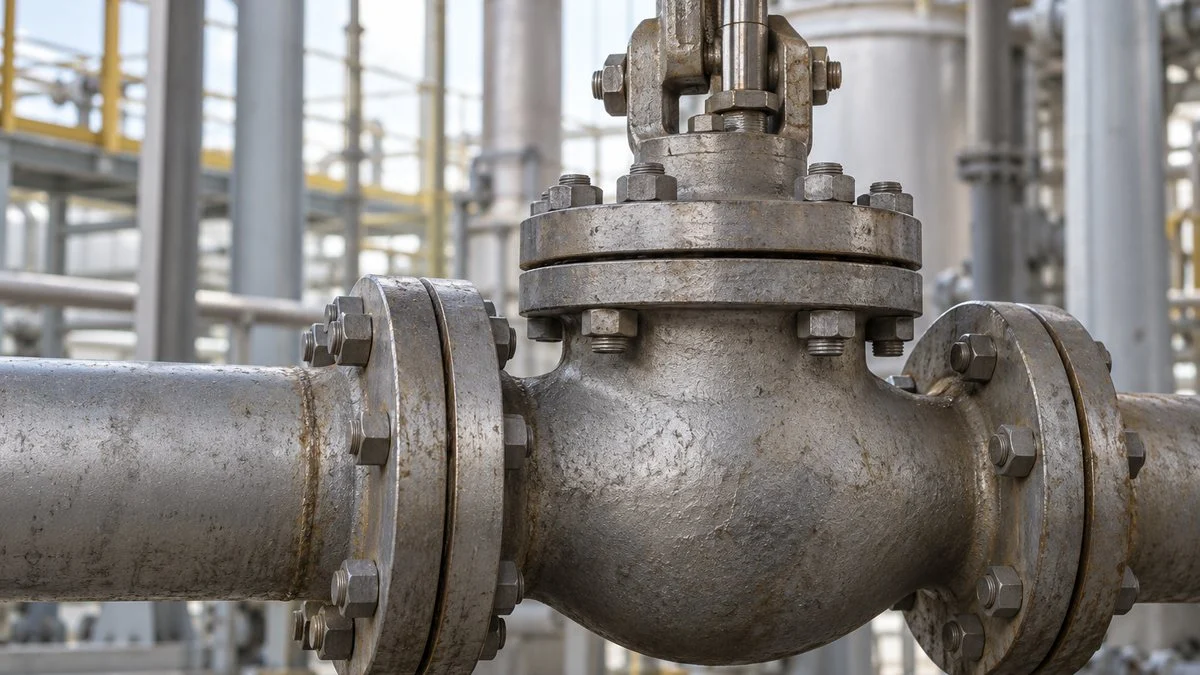
Decide the fail position by asking what state the process should move to after that failure, not by what is easiest to control. Evaluate open, closed, and hold as outcomes on the plant side, then pick the body, actuator, and accessories that deliver that position.
For heating with steam or hot water, shutting off the supply to prevent overheating is one design direction. Fuel valves also start from shutting off supply. Whether an ordinary control valve closing is enough to meet the required safety shutoff performance is a separate evaluation.
For cooling water, if reaction heat or residual heat must be removed, fail open on air loss is a candidate. If the cooling water pump or source stops at the same time, though, an open valve will not remove heat. Trace the failure across the whole system, including the cooling source.
For tank pressure control, the right move depends on whether you throttle the inlet or open the outlet to relieve pressure. Air services also differ (cooling, inerting, combustion air), so do not assign fail open just because of a service name.
Cooling and Heating: Trace the Whole Loop
Once the fail position is set, choose signal directions so normal control counteracts temperature deviations. The example below uses an air-to-close, spring-to-open cooling water valve, with the valve and positioner together set to close on increasing signal.
If the tank temperature rises above setpoint, more cooling water is needed. This valve opens when the controller output falls, so it needs a reverse-acting controller. As the temperature rises, the output falls, more cooling water flows, and the temperature comes back down.
Figure 4: A Fail-Open Cooling Water Valve Counteracting a Temperature Rise
Normal operation: PV↑ → MV↓ → opening↑ → cooling water↑ → PV↓.
The command goes to the valve with its positioner; the air circuit is omitted. On air failure the spring opens the valve, but cooling capacity must be evaluated separately if the cooling water source is lost at the same time.
For the same cooling duty with a valve that opens on increasing signal, use a direct-acting controller so the output rises as the temperature rises. For heating with a steam valve that opens on increasing signal, you need a reverse-acting controller that lowers the output, and the steam flow, as the temperature rises.
The heating loop runs: temperature up, controller output down, steam valve opening down, steam flow down, temperature down. Rather than memorizing "cooling = direct, heating = reverse," check that the loop gives negative feedback that cancels the deviation, including the valve's signal direction.
This check only confirms direction. It does not guarantee stable, non-oscillating tuning. Real flow response also depends on the valve's flow characteristic (linear or equal percentage), the pressure drop across the valve, the valve's speed, and controller tuning.
Write the 4–20 mA Endpoints on the Spec
A simple way to reduce misunderstandings is to state the valve opening at 4 mA and at 20 mA. Because a 4–20 mA signal starts at 4 mA, a 0% command can be told apart from a broken wire that carries no current. See 4–20 mA vs 1–5 V: why Japanese panels use 250 Ω inputs for how these loops are wired and checked.
The calculation below assumes fully closed at 4 mA, fully open at 20 mA, and a linear relationship in between. At 16 mA the commanded opening is 75%. If the valve is set fully open at 4 mA and fully closed at 20 mA, the same 16 mA gives 25%.
A 75% command does not mean 75% of maximum flow. Size the valve separately using its flow coefficient (Cv), and check the operating range against the pressure drops and flows at normal and maximum conditions.
Figure 5: Write the Signal Endpoints and Failure Conditions, Not Just the Action Name
Record the normal signal line and the out-of-range failures separately.
The dots mark the 16 mA example. Do not extend the line to treat 0 mA as a position; judge it by the signal-loss specification.
Changing the Action and Testing It at Commissioning
When you order a valve, give the required fail position plus the minimum supply air pressure and shutoff differential pressure it needs to get there. If the instrument air is too low, the actuator may not produce enough thrust, and the valve may not fully close even though the signal direction is correct.
Reversing the action is sometimes just a setting change and sometimes requires reconfiguring parts such as the spring, diaphragm, and stem. Swapping the plus and minus wires of the 4–20 mA loop is not a way to select action. It can cause loss of current or damage the device.
Re-routing only the air tubing also changes the supply and exhaust paths and the feedback direction, so it cannot be treated as a general change method. Give the maker the model number and the new fail position, agree on the parts, settings, and adjustment method, and only then change the specification. Changing the air paths also affects stroke speed; see pneumatic valve speed controllers: meter-out vs meter-in.
At commissioning, record the two normal signal endpoints, an intermediate opening, signal loss, air loss, and loss of each relevant power supply as separate results. Match valve tags and air circuits against the P&ID and instrument datasheets, and compare the opening shown on the HMI with how the valve actually moves. If a valve fails to reach its position in time, the system may raise a travel-timeout alarm, covered in valve sticking or slow to open? Reading a jutai alarm.
Run failure tests only with the equipment safely isolated, under an approved procedure that accounts for residual air pressure and stored spring energy. Avoid checking by pulling air or signal while the unit is running, and keep hands away from moving stems and actuators.
Fail-safe is a design principle: on failure, move the process to the safe side. Beyond the "fail closed" label, evaluate shutoff performance, time to reach position, and failures of other equipment, and assess plant safety together with the interlock protective actions. For how those circuits appear on Japanese drawings, see interlock circuit diagrams on Japanese drawings.
Checklist: Valve Action Items on a Japanese Datasheet
Use this list when reviewing a control valve datasheet or I/O list from a Japanese supplier. Each line should have an explicit answer, not just "正作動" or "NC."
- Opening at 4 mA and at 20 mA (and whether the relationship is linear)
- Actuator type: single-acting (spring return) or double-acting; which side the air acts on
- Air action: air to open (空気開) or air to close (空気閉)
- Body action: push-down-to-close or push-down-to-open
- Positioner output: direct or reverse, and its behavior on signal loss
- Fail position stated per failure: loss of air, loss of signal, loss of power (and to which device)
- For fail-last (FL): the lock-up device, allowable leakage, and required hold time
- Solenoid valves: de-energized state and which air paths are open
- Minimum supply air pressure and shutoff differential pressure for the fail position
- Controller action (direct or reverse) checked against the full loop direction
- P&ID fail letters (FO/FC/FL/FI) match the datasheet
Questions to Ask the Japanese Side
- When your datasheet says 正作動 or 逆作動, does it refer to the actuator, the whole valve, or the positioner?
- Does "NC" here mean the position on loss of air, on de-energizing a solenoid, or both?
- Where does the valve go on loss of 4–20 mA signal while air is still available?
- Which devices in the valve assembly need power, and what happens when each one loses it?
- If we need to reverse the action on site, is it a setting change or a parts change? Which parts and procedure?
Sample Inquiry Email
Subject: Confirmation of fail action for control valve [tag number]
For valve [tag number] (model [model number]), please confirm the following: (1) valve opening at 4 mA and 20 mA; (2) actuator air action (air to open or air to close) and body action; (3) final valve position on loss of instrument air, on loss of input signal with air available, and on loss of power to the positioner and solenoid valve; (4) minimum supply air pressure required to reach the fail position against [xx] MPa differential pressure. If the term 正作動/逆作動 on the datasheet refers to a specific device, please tell us which one. Thank you.
Where This Guide Does Not Apply
Naming varies by manufacturer, product family, and project. Some Japanese makers use 正作動 for the actuator, others for the whole valve, and on-off valve catalogs may label the same idea as NC/NO. Always follow the specific model's instruction manual and the project's drawing legend over a general table like the one above.
The figures here describe spring-and-diaphragm globe valves in concept. Rotary valves, electro-hydraulic actuators, and safety shutoff valves may have additional design rules and approvals; check the maker's documentation. This article explains how to read and question a specification; it is not a procedure for changing valve action or testing failure modes.
FAQ
Does NO Mean the Valve Is Fully Open During Normal Operation?
No. NO describes the position in the product's defined de-energized or unpressurized state, not the opening during normal operation. For a spring-return pneumatic valve, read it alongside "fail open on loss of air." For a solenoid valve, read it as which ports are connected when the coil is de-energized.
Is a 4 mA Signal the Same as the Fail Position?
No. 4 mA is the normal low-end command, and air is still available to drive the valve. On air failure, the air force is gone, so check the spring return and the positioner and accessory circuits separately rather than inferring from the 4 mA position.
Does a Double-Acting Actuator Stop Where It Is on Power Loss?
Not necessarily. If air remains during a power loss, some configurations open or close depending on the de-energized position of the switching valve. On air loss, a double-acting actuator without a spring has no defined position, so if hold is required, specify a lock-up circuit and the required hold time.
Is the Controller Always Direct Acting for Cooling?
Only if more signal means more cooling water. In that case, the controller raises its output as temperature rises, which is direct action. If the valve closes on increasing signal, as in Figure 4, the controller must be reverse acting. Trace the direction from output to cooling flow.
Is Fail Position Chosen Differently for On-Off Valves and Control Valves?
The logic is the same: decide the position for each failure first, then match the normal command to open and close. An on-off valve uses two states, while a control valve also uses intermediate openings, so there are more items to check for travel range and position confirmation.
Sources
- Actuator and body combinations: DwyerOmega, "Control Valve Actuator Sizing and Valve Action Selection"
- Direct- and reverse-acting diaphragm actuators and fail action with push-down-to-close bodies: Emerson, Fisher 3025 diaphragm actuator product bulletin
- Diaphragm actuator construction and reversing action: Azbil, CV3000 series three-way control valve AMT/HDT instruction manual (Japanese)
- Positioner direct/reverse output and position control: Yokogawa, VP200 electro-pneumatic positioner, sections 2.1–2.3 (Japanese)
- Controller direct/reverse action and deviation: Yokogawa, YS1500/YS1700 user's manual, section 2.3 (Japanese)
- Electric valve behavior on signal loss and power loss: Azbil, AGVB/AGVM electric single-seat control valve, 3-2-1 (Japanese)
- Holding position on air loss: Azbil, VF02 air lock valve (Japanese; discontinued product, function example)
- Single-acting vs. double-acting and failure types: Emerson, FieldQ installation, operation and maintenance manual, 2.2–2.3
- FO/FC/FL/FI fail-position notation on P&IDs: Hardhat Engineer, "Fail Open, Fail Closed, Fail Lock in Control Valves"
- Spring return and NO/NC labeling: High Pressure Equipment Company, "Air Operated Valves"
Original article in JapaneseThis guide is adapted from a MONOSCOPE article written for readers in Japan: 調節弁の正動作・逆動作とは?NO/NCと失気時の位置、使い分け
About the editor
 MONOSCOPE EditorFOUNDER & EDITOR
Spent about ten years at a plant equipment maker and a plant engineering company, proposing, designing, and commissioning equipment, then moved into web marketing. Now a web consultant for B2B manufacturers, helping them explain their products and technology. Licensed in Japan as an Energy Manager and a Third-Class Chief Electrical Engineer.
Has run an engineering blog since 2017 (500+ articles) and a Japanese YouTube channel with about 20,000 subscribers. Each English guide is written from the Japanese shop-floor point of view and checked against the cited standards.