Pneumatic Valve Speed Controller: Meter-Out vs Meter-In
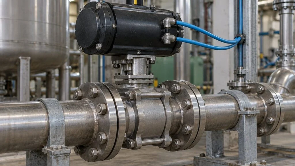
You are commissioning or maintaining a Japanese-built unit, and an air-operated valve slams shut, opens far more slowly than the one next to it, or trips a stroke-time alarm after someone "just touched the knob." The parts list or the instrument drawing calls the small fitting on the actuator port a スピコン (supikon). That is Japanese shorthand for speed controller: a flow control valve that throttles the air going into or out of the actuator, and so sets how fast the valve opens and closes.
Plants use speed controllers to soften pressure surges in the piping and to keep a sequence of valves and machines in step. Slowing a valve down is not always safe, though. An emergency shutoff valve that must close within a set time can become a problem if it is throttled too far.
Choosing one means deciding not only how many seconds the stroke should take, but also which direction of airflow you throttle. This guide covers how a speed controller works, meter-out vs. meter-in, spring-return vs. double-acting actuators, what to record when you adjust one, and what to ask the Japanese supplier.
Contents
- What a Speed Controller Does on a Pneumatic Valve
- Meter-Out vs. Meter-In
- Spring-Return vs. Double-Acting Actuators
- Why Valves Need Speed Control, and When Slower Is Wrong
- Selecting a Speed Controller
- Measuring Stroke Time: Open, Close, and Loss of Air
- After Adjustment: Lock It, and Never Use It as a Shutoff
- Stroke-Time Checklist and Questions for the Japanese Supplier
- Limits of This Guide
- FAQ
- Sources
What a Speed Controller Does on a Pneumatic Valve
A pneumatic automatic valve uses an actuator to turn compressed air into rotary or linear motion that opens and closes the valve. In a typical setup, a solenoid valve switches the air path, and a speed controller in that path throttles the flow.
The solenoid valve only switches between supply and exhaust; it is not meant to fine-tune how fast the valve moves. Actual speed depends on supply pressure, resistance in the tubing, the solenoid valve's flow capacity, and the actuator's volume and load.
The pressure and quality of the instrument air also matter. Treat everything from the air source to the exhaust port as one system, not just the speed controller setting.
| Japanese term | Meaning |
|---|---|
| スピコン (supikon), スピードコントローラ | Speed controller (pneumatic flow control valve with a check valve) |
| メータアウト (meta auto) | Meter-out: throttles air leaving the actuator |
| メータイン (meta in) | Meter-in: throttles air entering the actuator |
| 単動 / スプリングリターン (tando / supuringu ritan) | Single-acting / spring-return actuator |
| 複動 (fukudo) | Double-acting actuator |
| 電磁弁 (denjiben) | Solenoid valve |
| 計装用空気 (keiso-yo kuki) | Instrument air |
| 残圧 (zan-atsu) | Residual pressure trapped in tubing or the actuator |
Inside: A Needle Valve Plus a Check Valve
A typical speed controller combines a needle valve, which changes the size of the flow gap, with a check valve. In the controlled direction, the check valve closes and all air must pass the needle. In the opposite direction, the check valve opens a bypass, so air flows much more freely.
Figure 1: Metered Flow Through the Needle, Free Flow Through the Check Valve
A concept drawing with the two parallel paths laid out flat. It is not an actual cross section or an ISO/JIS circuit symbol.
The free-flow path still has some resistance. Whether a given direction is metered depends on the model (meter-in or meter-out) and how it is installed.
Turning the knob moves the needle and changes the effective flow area. Over part of the range, a small turn changes the flow a lot, so the number of turns and the stroke time are not simply proportional.
Two models can look almost identical and still meter opposite directions. Compare the marking on the body with the circuit diagram and trace the flow path before you install one. That is the starting point for controlling the opening speed or the closing speed you intended.
Meter-Out vs. Meter-In
Meter-out throttles the air leaving the actuator; meter-in throttles the air entering it. To tell which side is which, also look at where the speed controller is mounted.
When you pressurize one side of a double-acting cylinder, the air on the other side is pushed out. Meter-out throttles that exhaust and builds back pressure, which is why it is a common way to keep cylinder speed steady.
Figure 2: On a Double-Acting Actuator, Meter the Air Being Pushed Out
Flow at the moment the piston moves right. On the return stroke, the supply and exhaust sides swap.
This explains the flow with two speed controllers and a switching valve. It is not piping instructions for any product. At low speeds, or with residual pressure or certain loads, a different circuit may be needed.
In-line types fit in the middle of the tubing, while other types screw into the actuator port, and you trace the flow direction differently on each. If you swap parts based on appearance alone, the free-flow and metered directions can end up reversed. SMC's manual for its in-line speed controllers warns that mounting one backward is dangerous: the needle will not control speed and the actuator may move suddenly.
Some circuits use models that meter both supply and exhaust. Because low-speed starts and load also affect motion, start from the actuator maker's example circuits and choose parts that give the motion you need.
Spring-Return vs. Double-Acting Actuators
A spring-return (single-acting) actuator moves one way on air pressure and returns the other way on spring force. It can be air-to-open and spring-to-close, or the reverse; the choice follows the valve position the process needs when air is lost.
Related: Direct vs Reverse Acting Control Valves: NO/NC, FO/FC/FL
Figure 3: With Spring Return, How Easily Air Exhausts Affects Return Speed
Concept cross section of a single-acting cylinder. Whether the valve actually opens or closes depends on how the mechanism is arranged.
A double-acting actuator uses air for both opening and closing, with the solenoid valve switching supply and exhaust. Not every automatic valve has a spring, so start by reading the drive type from the specification.
A single one-direction speed controller will not necessarily let you set opening and closing speeds independently. If you need to adjust each stroke of a single-acting actuator, you need a suitable arrangement, such as a circuit that handles both supply and exhaust.
Why Valves Need Speed Control, and When Slower Is Wrong
The main purpose is to give the valve enough time to open and close so the fluid and the equipment do not see sudden changes. In normal operation, the setting reduces shock in the piping. In an upset, it must still meet the required shutoff time.
Liquid Lines: Fast Closing and Water Hammer
When a valve closes suddenly on a line carrying water, oil, or another liquid, the change in flow velocity causes a pressure swing. Depending on pipe length, velocity, and how the valve closes, this can become water hammer, a heavy shock that loads equipment and pipe supports.
A speed controller slows the valve, but that alone does not solve every pressure surge. Pump trips, backflow, and elevation differences in the system can also cause shock, so separate the causes by the situation in which the shock occurs.
This matters especially for rotary valves (ball and butterfly types): even when the disc or ball turns at a constant speed, the flow does not necessarily change at a constant rate. Judge the stroke time against the valve's flow characteristic, including the change near the closed position.
Steam Lines: Condensate and Rapid Condensation
If you send a large amount of steam into a cold steam line all at once, a lot of condensate forms as the pipe warms up. That water can be driven along at high speed by the steam, or steam can condense suddenly, and either can cause a violent impact.
Figure 4: Shock You Address With Valve Speed vs. Shock You Address With Drainage
Evaluate the closing motion together with the piping system.
Look at warm-up, drainage, and piping condition, not only valve operation.
Do not treat fast closing on a liquid line and rapid condensation of steam as the same inertia problem. Different causes need different fixes.
Opening the valve slowly to limit the initial steam flow is one measure during warm-up. Draining condensate so that water does not collect in the line is just as important for preventing steam hammer.
With hammer caused by rapid condensation, the problem can continue even when the valve opens slowly. Before you slow down the valve that bangs, find where the noise starts and check for condensate pooling and the condition of the steam traps and piping.
Sequences: Speed Is Not an Interlock
On equipment that moves several valves and machines in order, consistent speeds keep the conditions for the next step consistent. Treating the open command and the "valve is open" signal as two separate things lets you see how long the valve actually takes.
Even with simple on-off control, the mechanism takes some time to travel. Combine the command with position detection by limit switches so you can tell "commanded" from "done." If the confirmation does not arrive in time, the control system may raise a travel-timeout alarm, called jutai on many Japanese systems; see Valve Sticking or Slow to Open? Reading a Jutai Alarm.
Slowing the valve with a speed controller does not guarantee the electrical sequence. The conditions that allow the next machine to start must be designed separately, as interlocks in the control system.
Related: Interlock Circuit Diagrams: How to Read Japanese Drawings
Selecting a Speed Controller
Before deciding whether to fit one, list the normal opening and closing times and the motion required in an upset. If the same valve must close gently to avoid water hammer but also close fast to stop a hazard, resolve both requirements at the level of the whole circuit.
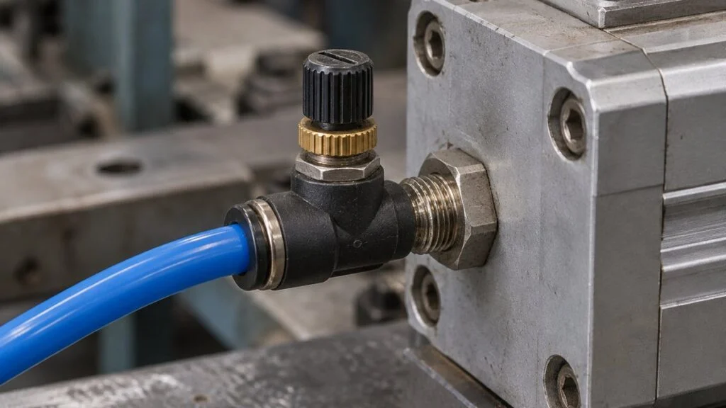
Check these first: connection size, flow adjustment range, operating pressure and temperature, and the controlled flow direction. Two parts with the same thread can have different flow characteristics, so match the specifications down to the last characters of the model code when you replace one.
A larger flow rating does not make fine speed adjustment easier. If the part is oversized for the flow you need, all the useful adjustment falls into a narrow part of the range. Compare models suited to low speeds as well.
Catalog air flow is sometimes stated as a value converted to reference pressure and temperature conditions. Before you divide the actuator's internal volume by that flow, make sure the reference conditions and the supply and exhaust pressures match.
Air left in the tubing is still under pressure. Shutting off the supply and releasing the residual pressure are two separate steps, and the equipment must be isolated under your plant's procedure before anyone enters the range of motion. SMC's manuals also warn that actuators can move suddenly because of residual pressure.
Near steam valves, the ambient temperature around the pneumatic parts is a selection condition, not only the process fluid. Allow for heat conducted from the valve and the distance from hot piping, and place the parts and tubing where they stay within their rated range.
Not a Regulator, Not a Positioner
A regulator sets air pressure; a speed controller changes how easily air flows. Lowering supply pressure to slow a valve can also take away the force the actuator needs, so keep the two roles separate.
A positioner compares the command with the actual valve position and drives the valve to the target opening. Position control by a positioner and speed adjustment by a speed controller can sit in the same air circuit, but they do different jobs.
Related: Electro-Pneumatic vs. Pneumatic Positioners: How They Work
For example, when a 4–20 mA signal sets the valve opening, the speed controller does not receive that current or stop the valve at a target position. Throttling the air too much also changes the valve's response, so on a control valve, evaluate it as part of the control loop.
Related: 4-20 mA vs 1-5 V: Why Japanese Panels Use 250 Ω Inputs
The Cv value, which describes how easily the process fluid passes through the valve, is a different quantity from the speed controller's air flow. A big valve does not automatically need a big speed controller; size the air circuit from the actuator volume and the required stroke time.
Measuring Stroke Time: Open, Close, and Loss of Air
During commissioning, decide which command starts the clock and what counts as "done" before you record stroke times. Splitting the time into the delay before the valve starts to move, the travel itself, and the moment the end-position signal arrives makes problems easier to trace.
Figure 5: Which Part of "Command to Done" Are You Measuring?
One example timeline. Measure opening and closing separately, and record which signal and conditions you used.
A schematic with no time scale; the lines are not measured waveforms. Depending on where the switch is set, the end-position signal can arrive before travel actually ends. A "fully closed" signal and the seat's ability to shut off flow are judged separately.
The same setting can give a different stroke when the supply pressure or the process differential pressure changes. Record the pressures, the equipment condition, and the knob position together with the times. That record lets you compare before and after maintenance.
Measure supply pressure while the valve is moving, not just at rest. If supply pressure dips only when several devices operate at once, look at supply capacity upstream before changing the speed controller.
Also compare the first stroke after residual pressure has been released with strokes made back to back. If the exhaust side has no pressure at the start of the first stroke, meter-out back pressure has not built up yet, and the actuator may lurch on that stroke only.
Where the end-position signal switches depends on how the switch or sensor is set, and it may not match the mechanical end of travel exactly. Confirming the "fully closed" signal and confirming that the seat actually stops the fluid as required are two different checks, and each needs its own test.
Record the model number, mounting location, tubing size, opening and closing times, and how the setting is locked. If maintenance changes tubing length or exhaust parts, do not just return the knob to its old position; measure again under the same conditions.
On spring-return actuators, check normal solenoid operation and loss-of-air behavior separately. Even with a spring return, an exhaust restriction slows the stroke, and in a circuit where air gets trapped, the valve may not return at all. Verify that an exhaust path exists on loss of supply and that the valve moves within the required time.
After Adjustment: Lock It, and Never Use It as a Shutoff
Make adjustments only after the hazards from moving parts and residual pressure are under control, and follow the product's instruction manual. After a change, test both the opening and the closing stroke, then lock the setting with the lock nut or the specified method. SMC notes that a loose lock nut can change actuator speed.
A general-purpose speed controller is for flow adjustment, not for shutting off air. SMC's manual for its in-line speed controllers states that they cannot be used as stop valves for zero leakage, that some leakage is allowed by the specification, and that tightening the needle to stop flow completely can damage the product.
If a valve has become slow, a changed setting is only one possibility. Low air pressure and a clogged exhaust port are others. Check the whole path, including fittings, tubing, silencers, and the solenoid valve, to find resistance outside the speed controller.
If the valve does not start moving and then suddenly jumps, look at valve friction and the actuator's force margin as well. Do not stop at opening the speed controller further; check supply pressure, actuator sizing, and the mechanical condition of the valve.
| What you see | What to check separately |
|---|---|
| Only the opening speed changed | Direction of the metered flow; supply and exhaust paths |
| Slow in both directions | Supply pressure, tubing resistance, shared air supply |
| Lurches only on the first stroke | Residual pressure, load, circuit conditions at start-up |
| Speed drifts some time after adjustment | Whether the setting is locked, air conditions, exhaust parts |
Stroke-Time Checklist and Questions for the Japanese Supplier
Record Sheet for Each Valve
- Valve tag, actuator type (spring-return or double-acting), and required position on loss of air
- Speed controller model code, mounting location (in-line or on the port), and metered direction (meter-in or meter-out)
- Tubing size and length, solenoid valve model, silencer or exhaust parts
- Supply pressure at rest and during the stroke
- Process conditions at the time of the test (differential pressure, temperature, line full or empty)
- Opening and closing times, with the start signal and end signal used for each
- First stroke after depressurizing vs. repeated strokes
- Stroke time on loss of air (spring-return valves) and the required maximum time
- Knob position and how the setting is locked; who adjusted it and when
Questions to Ask the Japanese Side
- What opening and closing times are required for this valve, and what is the basis (water hammer, sequence, emergency shutoff)?
- Is there a maximum closing time for emergency or loss-of-air operation, and how was it verified?
- Which speed controller model is fitted, and is it meter-in or meter-out? Where exactly is it mounted?
- Can you send the pneumatic circuit diagram for the actuator, including solenoid valve, speed controllers, and exhaust parts?
- What stroke times and supply pressure were recorded at the factory acceptance test or commissioning?
- What is the alarm timeout for travel (jutai) on this valve, and does it need to change if the stroke time changes?
Sample Inquiry Email
Subject: Valve [tag number] – speed controller (supikon) setting and required stroke time
Hello [name],
We need to adjust the speed controller (スピコン) on valve [tag number] in [unit]. The valve currently [opens/closes] in [time] at a supply pressure of [value]. Before we change anything, could you send us:
1. The required opening and closing times and their basis
2. Any maximum closing time for emergency shutoff or loss of air
3. The pneumatic circuit diagram and the speed controller model (meter-in or meter-out)
4. The stroke times recorded at FAT or commissioning
5. The travel alarm (jutai) timeout for this valve
Thank you,
[your name]
Limits of This Guide
- Speed controller construction, metered direction, and allowed operating conditions differ by maker and model. The product's catalog and instruction manual take priority.
- The figures are concept drawings, not circuit diagrams or piping instructions. Use the actuator maker's example circuits and the supplier's drawings.
- Required stroke times, especially for emergency shutoff, are set by the plant's design and safety basis. This guide describes what to check and who to ask, not how to set them.
- Isolation, depressurizing, and work inside the range of motion follow your plant's procedures and local regulations.
- Water hammer and steam hammer have several causes. Valve speed is only one factor.
FAQ
Does Every Pneumatic Automatic Valve Need a Speed Controller?
No. Whether you need one depends on the required stroke times and the fluid and equipment conditions. It is a useful way to avoid sudden opening or closing, but the circuit and setting must not compromise any emergency action the valve has to perform.
Can One Speed Controller Adjust Both Opening and Closing?
Not necessarily. A typical one-way model meters only one flow direction, so it may not let you set opening and closing independently. Check whether the actuator is single- or double-acting and where the part is mounted, and choose a device that handles both supply and exhaust if you need both.
Does Meter-Out Always Give Smooth Motion?
No. Meter-out is common for cylinder speed control, but low speeds, the first stroke, residual pressure, and load all change how the actuator moves. Check the required speed range and circuit against the maker's documents, and include the first stroke in your tests.
Will Slowing the Valve Stop Steam Hammer?
Not always. Opening slowly helps limit flow during warm-up, but speed adjustment alone may not stop hammer caused by rapid condensation. Check where condensate forms and collects, along with the drainage equipment and piping, and fix the actual cause.
Can I Shut Off Air by Closing the Speed Controller Fully?
No. Flow-control speed controllers can allow some leakage by design, so they cannot serve as isolation valves for safe work. Use the specified supply shutoff and residual-pressure release, and never rely on a tightened needle instead.
Sources
- Not a stop valve, mounting direction, lock nut: SMC, speed controller with One-touch fitting (in-line type) instruction manual
- Residual pressure and sudden actuator movement: SMC, ASP series speed controller with pilot check valve instruction manual
- Safety precautions for speed controllers: SMC, ASG stainless steel speed controller instruction manual (Japanese)
- Construction and model types: SMC, AS-M speed controller catalog (Japanese)
- Choosing meter-in or meter-out: Nitta, FAQ on meter-in and meter-out (Japanese)
- Circuits and flow characteristics: CKD, SCL2/SCD2 catalog (Japanese) and SCL2/SCD2 instruction manual (Japanese)
- Pneumatic actuator construction: KITZ, small automated valves catalog J-301=59 (Japanese)
- Accessories and air circuits for automated valves: KITZ, automated valves catalog J-350=50 (Japanese)
- Positioner operating principle and position feedback: SMC, electro-pneumatic positioner catalog (Japanese)
- Water hammer in steam and condensate systems: TLV, water hammer in condensate transport piping; mechanism (Japanese), countermeasures (Japanese), starting and stopping steam supply (Japanese)
Original article in JapaneseThis guide is adapted from a MONOSCOPE article written for readers in Japan: スピコンとは?自動弁の開閉速度を調整する仕組みと使い方
About the editor
 MONOSCOPE EditorFOUNDER & EDITOR
Spent about ten years at a plant equipment maker and a plant engineering company, proposing, designing, and commissioning equipment, then moved into web marketing. Now a web consultant for B2B manufacturers, helping them explain their products and technology. Licensed in Japan as an Energy Manager and a Third-Class Chief Electrical Engineer.
Has run an engineering blog since 2017 (500+ articles) and a Japanese YouTube channel with about 20,000 subscribers. Each English guide is written from the Japanese shop-floor point of view and checked against the cited standards.