Interlock Circuit Diagrams: How to Read Japanese Drawings
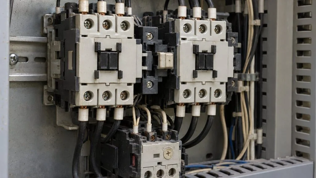
A Japanese supplier sends the electrical drawing package for a pump skid or a machine. Somewhere in it are a relay schematic with contacts marked "a" and "b," a block diagram with AND and NOT boxes, and a table titled インタロック表 (intarokku-hyo, interlock list). You are asked to review it, approve it, or use it to find out why a motor will not start. The logic is familiar. The symbols, the drawing direction, and the Japanese labels may not be.
This guide is about reading those drawings, not designing them. It covers what "interlock" means on a Japanese drawing, how Japanese electrical symbols relate to IEC 60617, how to read a block diagram as a relay circuit, a forward/reverse motor circuit as a worked example, and how to read an interlock list. It ends with a review checklist and questions you can send to the supplier.
Contents
- What "Interlock" Means on a Japanese Drawing
- Japanese Electrical Symbols: JIS C 0617 and IEC 60617
- Reading a Basic Relay Interlock
- Reading an Interlock Block Diagram
- Worked Example: Forward/Reverse Motor Interlock
- Reading a Pump Interlock List (Interlock Table)
- Safety Interlocks: What the Drawing Cannot Tell You
- Checklist: Reviewing Interlock Drawings from a Japanese Supplier
- Questions to Send the Japanese Supplier
- Limits of This Guide
- FAQ
- Sources
What "Interlock" Means on a Japanese Drawing
An interlock is a control that keeps a function disabled until a set of conditions is met, or stops it when a condition is lost. It has two purposes: protecting equipment and protecting people. A microwave oven that will not heat with the door open and a pump that will not start with an empty tank are both interlocks.
Japanese sources describe the same idea in slightly different words depending on the field:
- Motor starters (Mitsubishi Electric catalog): when two contactors must never be on at the same time, the one that closes prevents the other from closing. This can be done mechanically or electrically with auxiliary b-contacts.
- Machine safety (Japan's Ministry of Health, Labour and Welfare): an interlocked guard prevents a hazardous machine function from starting until the guard is closed, and issues a stop command if the guard is opened during operation.
- Nuclear (ATOMICA encyclopedia, Japan Atomic Energy Agency): a mechanism that lets one process operate only when another process is in the proper state. Reactors include many of them to stop chains of operating errors and malfunctions.
- Safety equipment (azbil Technical Review): interlocks for safety protection need fail-safe and foolproof construction. Foolproof means the design prevents a wrong action even when an operator tries to make one.
You will see the word spelled two ways in Japanese: インタロック (intarokku) and インターロック (inta-rokku). They mean the same thing. Mitsubishi Electric's contactor catalog uses the first, and JIS B 9710 uses the second.
Stop Condition or Permissive? Check This First
On Japanese drawings and specifications, "interlock" is used in two opposite senses. In one, the interlock is the condition that stops the equipment. In the other, it is the condition that permits the equipment to run. Before you read any interlock logic, find out which convention the supplier uses.
"Interlock established" means the opposite thing in each style: stop, or OK to run.
The same equipment can be documented either way, depending on the manufacturer or the designer.
Written both ways, the same low-level condition reads: stop-condition style, "low level activates the interlock, so the pump cannot start"; permissive style, "normal level establishes the start permissive, so the pump can start." Two Japanese words help you tell them apart: 作動 (sado, activated) tends to appear in stop-condition wording, and 成立 (seiritsu, established or met) in permissive wording. Even so, confirm with the supplier rather than relying on wording alone.
Japanese Electrical Symbols: JIS C 0617 and IEC 60617
Japanese electrical drawings follow JIS C 0617, "Graphical symbols for diagrams." It is built on IEC 60617. The 2024 edition states that it was prepared from IEC 60617 as of 2024 without changing the technical content. It is formally marked as a modified adoption (MOD) because IEC 60617 is a database standard, while JIS splits it into 13 numbered parts. If you already read IEC-style schematics, the symbols on a current Japanese drawing will look familiar. JIS also has separate terminology standards for fields such as thermal power and hydraulics/pneumatics; to check the exact wording of any JIS, use the latest edition from the Japanese Industrial Standards Committee (JISC) or the Japanese Standards Association.
Two parts matter most for interlock drawings:
- JIS C 0617-7: switchgear, controlgear, and protective devices (contacts, contactors, relays, pushbuttons)
- JIS C 0617-12: binary logic elements (AND, OR, NOT and other logic symbols)
Older drawings are a different matter. For decades Japan used JIS C 0301, which included a set of Japan-specific symbols. JIS C 0617 replaced it in two stages, in 1997 and 1999, and the Japan-specific series was dropped in favor of the IEC symbols. On equipment built before then, or on drawings copied forward from old designs, you may still see the old symbols. When a symbol does not match anything you know, ask for the legend sheet (凡例, hanrei) rather than guessing.
Drawing direction can also differ from what US engineers expect. A US ladder diagram usually runs its rungs horizontally between two vertical rails. Japanese sequence diagrams (シーケンス図, shikensu-zu) are drawn both ways. The examples in this guide use a vertical layout, with supply lines at the top and bottom and each circuit running from top to bottom. Read it as a ladder diagram turned 90 degrees.
Japanese Terms on Interlock Drawings
| Japanese | Reading | English |
|---|---|---|
| a接点 / b接点 / c接点 | a-setten / b-setten / c-setten | NO (make) contact / NC (break) contact / changeover contact |
| 励磁 | reiji | Energized (coil) |
| 自己保持 | jiko-hoji | Self-holding (seal-in) circuit |
| 電磁接触器 (MC) | denji sesshokuki | Magnetic contactor |
| 電磁開閉器 | denji kaiheiki | Magnetic starter (contactor plus thermal overload relay) |
| サーマルリレー (THR) | samaru rire | Thermal overload relay |
| 押しボタンスイッチ (PB, BS) | oshi-botan suitchi | Pushbutton |
| 配線用遮断器 (MCCB, NFB) | haisen-yo shadanki | Molded-case circuit breaker |
| 正転 / 逆転 | seiten / gyakuten | Forward / reverse |
| 可逆式 (可逆形) | kagyaku-shiki | Reversing type (starter or contactor) |
| 寸動 (INCH) | sundo | Inching (jog) |
| 作動 / 成立 / 解除 | sado / seiritsu / kaijo | Activated / established (met) / released (cleared) |
| 起動阻止 | kido soshi | Start inhibit |
| 現場 / 中央 | genba / chuo | Local / remote (central control room) |
Reading a Basic Relay Interlock
Start with the simplest case. In the left circuit of Figure 2, pressing pushbutton BS1 energizes relay R1, R1's a-contact closes, and lamp L1 lights. The right circuit adds an interlock: L1 lights only when both BS1 and BS2 are pressed. The a-contacts of R1 and R2 are in series, so one alone does nothing.
Each added condition is another contact in series ahead of the output.
Redrawn in English from the figures in the Japanese edition of this article. Vertical layout: supply lines at top and bottom.
That is the pattern to look for on any relay drawing: conditions are contacts placed upstream of the device they control. In practice, interlocks are often combined with a self-holding circuit so that once the interlock trips, the equipment does not restart until someone presses a reset button.
Reading an Interlock Block Diagram
Japanese suppliers may also document interlocks as block diagrams (ブロック線図, burokku senzu), instead of or alongside relay schematics. Figure 3 shows a typical one: when conditions A, B, and C are all present, the interlock activates. That signal is inverted (NOT) and ANDed with the run button, so a run command goes out only while the interlock is not active. This is the stop-condition style from Figure 1.
Top: A AND B AND C activates the interlock. Bottom: NOT interlock AND run button gives the run command.
Redrawn in English from the Japanese edition. This vertical-bar AND style is one of several conventions; the supplier's legend sheet defines the symbols used on its drawings.
Every block in such a diagram maps to a way of connecting relay contacts. Once you know the mapping, you can translate between the block diagram and the schematic in either direction.
AND = contacts in series. OR = contacts in parallel. NOT = a b-contact.
Some drawings use other logic symbols for the same functions, such as the US distinctive shapes (D-shaped AND, curved OR) or the IEC/JIS C 0617-12 rectangles. The shape changes; the reading does not.
Figure 3 therefore describes the same thing as this relay circuit: the a-contacts of conditions A, B, and C in series drive an interlock relay, and that relay's b-contact sits in series with the run button. If the supplier gives you only one of the two forms, sketching the other is a quick way to check that you have understood the logic.
In a PLC or a distributed control system (DCS), the same conditions are built into the program, so no run command goes out until the permissive conditions are met. If the interlocks are implemented on a Mitsubishi, Omron, or Keyence PLC, How to Read Japanese PLC Programs: Mitsubishi X/Y/M/D explains the device names and Japanese comments you will meet. Level switches and limit switches enter the PLC or DCS as ON/OFF inputs, listed on the I/O list; see DI/DO, AI/AO, PI/PO Meaning: Reading a Japanese I/O List.
Worked Example: Forward/Reverse Motor Interlock
The forward/reverse motor circuit is the textbook interlock example, and you will meet it wherever a drawing set includes a reversing motor. Swapping any two of the three supply phases reverses a three-phase motor. (For a pump that runs backward because of phase sequence, see Pump Running Backwards? Phase Sequence and the Two-Phase Fix.) A reversing circuit uses two contactors to do the swap: MCF for forward and MCR for reverse. If both closed at once, the two swapped phases would be shorted together (a phase-to-phase short), which could trip the breaker and stop the equipment. The interlock exists to stop that from happening.
In the main circuit, MCR swaps two phases. In the control circuit, each side's b-contacts block the other side.
Simplified from the reversing control circuit example in Mitsubishi Electric's MS-T/N series contactor catalog, with the inching (INCH) circuit and other details removed. Some series contacts are reordered without changing the function. Actual terminal numbers and contact counts vary by model.
How to Trace the Control Circuit
Follow the forward side from top to bottom. Below the stop button (a b-contact) is the forward pushbutton in parallel with MCF's own a-contact, which seals the circuit in after the button is released. Next come two b-contacts in series: one on the reverse pushbutton and one on MCR. The MCF coil is last. A b-contact opens when its pushbutton is pressed or its contactor closes. While MCR is closed, its b-contact is open, so the MCF coil cannot be energized. The reverse side mirrors this. The thermal overload relay's b-contact, which opens on overload, is common to both sides.
The pushbutton b-contacts change how the circuit behaves. If you press the forward button while the motor runs in reverse, the forward button's b-contact cuts the reverse side. MCR drops out, its b-contact recloses, and MCF pulls in, so the direction changes without pressing stop. Whether the equipment should allow this is a design question for the supplier, covered under "Changeover Time" below.
For thermal overload relays and how they differ from other motor protection, see Shock Relay vs. Overload Relay.
Electrical vs. Mechanical Interlock
The b-contacts in Figure 5 form the electrical interlock. Reversing types from makers such as Mitsubishi Electric and Fuji Electric also have a mechanical one. Check which is shown on the drawing and which is actually installed.
One blocks the other contactor through wiring; the other blocks it with a physical link.
Mitsubishi Electric and Fuji Electric reversing types ship with a mechanical interlock as standard and with the electrical interlock wiring already in place.
Points to confirm on the drawing, based on the manufacturer documents in the Sources:
- Each side's b-contact from the other contactor sits in series just ahead of its own coil. In the Mitsubishi Electric example, these are MCR terminals 21-22 and MCF terminals 31-32.
- Reversing starters may arrive pre-wired. Mitsubishi Electric's reversing starters have two auxiliary b-contacts already wired as the electrical interlock, and Fuji Electric's reversing type ships with electrical interlock wiring.
- On models with a mechanical interlock, the manufacturer may specify which b-contacts to use. Mitsubishi Electric specifies the inner b-contacts on the mechanical interlock side.
- A molded-case circuit breaker (MCCB) is on the supply side of the main circuit to clear a phase-to-phase short if one occurs.
Changeover Time and Instant Reversal
An interlock does not make instant reversal safe. Because the circuit in Figure 5 lets the buttons switch direction directly, a very short gap between one contactor opening and the other closing can still cause a short circuit. Fuji Electric, for example, calls for a timer or other interlock to keep the switching time at 15 ms or more when its SC-E02RM to SC-E04RM reversing contactors are used for high-speed switching. The required time depends on the model and the application, so check the catalog for the actual contactor.
The motor side matters too. Oriental Motor does not recommend instant reversal of its three-phase induction motors, because the sudden reverse torque can damage the gearhead. Its guidance is to insert a short stop or to decelerate with an inverter before reversing. If the drawing shows direct reversal, ask the supplier how the changeover time and the mechanical load were considered.
When forward/reverse is controlled by a PLC, the program interlock should not be the only layer. The usual practice is to keep the b-contact electrical interlock and the mechanical interlock on the contactors downstream of the PLC outputs. If the drawings show only a software interlock, raise it in your review.
Reading a Pump Interlock List (Interlock Table)
For plant equipment, the interlock list (インタロック表 or インターロックリスト) is usually the quickest way into the interlock logic. It lists the interlock conditions for each piece of equipment, so you can see what happens, to which equipment, and how, without tracing the schematic or the program. There is no standard format; columns vary by plant and company. Figure 7 shows typical columns for a pump.
Common pump interlocks protect against running dry, running against a closed discharge valve, overload, and remote starts during local work:
- Low suction tank level: block the start, or stop the pump if running (prevents dry running).
- Discharge valve closed: do not allow extended running (prevents temperature and pressure rise from running against a closed valve).
- Motor overload: the thermal overload relay trips and stops the pump.
- Local/remote switch at "local" during field inspection: ignore start commands from the control room.
These conditions follow pump makers' warnings. Ebara's instruction manual for its end-suction centrifugal pumps, for example, warns that dry running can damage the casing, bearings, and shaft seal, and that the pump must not run with the discharge valve closed for one minute or longer.
With condition, action, and reset on one row, you can trace why the pump stopped.
Setpoints, delays, and tag numbers are illustrative only. Real values are set during design to suit the equipment specification and operating conditions.
The first row reads: "If tank level low lasts 5 seconds, P-101 cannot start, and if it is running, it stops. The condition clears when the level recovers, but an operator must restart the pump." When you review a supplier's list, check that each row makes three things clear:
- Type: does the condition only block a start (起動阻止, start inhibit), or does it also stop a running machine (停止, trip)?
- Delay: is there a time delay so that a momentary fluctuation does not cause a trip?
- Reset: does the interlock clear automatically when conditions return to normal, or does it need a reset (リセット) operation?
If the condition column uses the same tag numbers as the P&ID, you can match the list to the drawing and to the field quickly. Ask for this if it is missing. See PFD vs P&ID on Japanese Projects for how Japanese P&IDs are organized.
Related: How to Read P&ID Instrument Symbols: ISA-5.1 vs JIS
Safety Interlocks: What the Drawing Cannot Tell You
Interlocks that protect people, such as a press that runs only with both hands on the buttons or a guard that must be closed before the machine starts, are covered by machine-safety standards. The two JIS standards you are most likely to see cited are identical to ISO standards:
- JIS B 9710:2019 (identical to ISO 14119:2013): principles for the design and selection of interlocking devices associated with guards. The basic form: the machine cannot start until the guard is closed, and opening the guard during operation issues a stop command.
- JIS B 9712:2022 (identical to ISO 13851:2019): principles for the design and selection of two-hand control devices. While both hands are on the controls, they cannot be in the danger zone.
A safety interlock is not finished once the circuit is drawn. The hazards have to be identified, the required safety performance decided, and only then are the components and circuit chosen. The schematic itself does not record those steps. For a safety interlock, ask the supplier for the risk assessment and the basis for the required safety performance, and have your own safety function or the designated responsible person review them. This guide does not tell you whether a given safety circuit is adequate.
Checklist: Reviewing Interlock Drawings from a Japanese Supplier
- Convention: stop-condition style or permissive style? Is it stated on the drawing or in the interlock list?
- Symbol legend (凡例): included? Any symbols from the old JIS C 0301 or company-specific symbols?
- Consistency: do the block diagram, the relay schematic, the PLC program, and the interlock list describe the same logic?
- Each interlock row: type (start inhibit or trip), setpoint, delay, and reset method all filled in?
- Tag numbers: do they match the P&ID and the I/O list?
- Contact types: a-contact or b-contact for each field device? For trip signals, which state means "trip"?
- Reversing motors: both electrical and mechanical interlocks shown? Changeover time or a stop before reversing addressed?
- PLC-controlled outputs: hardware interlocks kept on the contactors, not only in the program?
- Local/remote switching: is remote start blocked while the switch is at "local"?
- Safety interlocks: risk assessment and the applicable standards (for example JIS B 9710 / ISO 14119) provided?
- Testing: is each interlock included in the FAT and SAT test procedures? See FAT and SAT with Japanese Suppliers.
Related: 4-20 mA vs 1-5 V: Why Japanese Panels Use 250 Ω Inputs
Questions to Send the Japanese Supplier
You can paste these into an email. Replace the bracketed parts.
- In your interlock list, does "interlock activated" (インタロック作動) mean the equipment is stopped, or that it is permitted to run? Please state the convention on the drawing.
- Please send the symbol legend (凡例) for the electrical drawings. Do any drawings use symbols from the former JIS C 0301 or your own company standard?
- For [P-101], please confirm the setpoint, delay time, and reset method for each interlock condition.
- Which interlocks reset automatically when the condition clears, and which require a manual reset? Where is the reset button or reset command?
- For the reversing motor [M-201], are both electrical (b-contact) and mechanical interlocks provided? How is the changeover time between forward and reverse handled?
- Are any interlocks implemented only in the PLC or DCS program? If so, please list them.
- For the guard and safety interlocks, please share the risk assessment and the standards applied.
- Please confirm that every interlock in the list will be tested during the FAT, and send the test record format.
If you need to approve the drawings formally, Approval Drawings (Shonin-zu) in Japan explains how the review-and-return cycle works.
Limits of This Guide
- The circuits are simplified for explanation. They are not design references or wiring instructions. Terminal numbers, contact counts, and recommended wiring vary by maker and model; follow the manufacturer's documents.
- Interlock list formats and the meaning of "interlock activated" vary by company, plant, and project. Confirm the convention with the supplier for each project.
- Setpoints and delays in Figure 7 are fictional. Real values come from the equipment specification and the process design.
- The adequacy of a safety interlock is decided through risk assessment and the applicable standards and regulations at your site, by the people responsible for them. This guide does not assess safety circuits.
- Do not bypass an interlock to run equipment. Any temporary bypass must follow your site's approved procedure and be removed afterward.
FAQ
What Is the Difference Between an Interlock and a Self-Holding Circuit?
They do different jobs. A self-holding (seal-in) circuit keeps a contactor energized through its own a-contact after the start button is released. An interlock prevents operation until conditions are met. Circuits such as forward/reverse use both together.
What Happens If Forward and Reverse Are Pressed at the Same Time?
In a relay circuit with pushbutton b-contacts like Figure 5, pressing both cuts both sides, so neither contactor closes. In a program, the result depends on how the controller executes. Omron's FAQ shows that a PLC, which scans from top to bottom, turns on only the output evaluated first, while its ZEN programmable relay can turn both on. That is why programs are written to give one side priority or to block both, and why the contactor-level interlocks stay in place.
Are JIS Electrical Symbols the Same as IEC Symbols?
For current drawings, essentially yes. JIS C 0617 is based on IEC 60617, and the 2024 edition keeps its technical content unchanged; it is labeled MOD only because of the way it is split into parts. Drawings based on the older JIS C 0301 can contain Japan-specific symbols, so ask for the legend if a symbol is unfamiliar.
What Do "a-Contact" and "b-Contact" Mean?
An a-contact is normally open (NO, or make contact): it closes when the device operates. A b-contact is normally closed (NC, or break contact): it opens when the device operates. A c-contact is a changeover contact with a common terminal.
The Equipment Will Not Start Because of an Interlock. Where Do I Look?
Start with the interlock list or the DCS/HMI screen to find which condition is not met. Some circuits stay latched even after conditions return to normal and need a reset. Do not jumper out the condition to run the equipment; if a bypass is unavoidable, follow your site's approved procedure and restore it afterward.
Sources
- JIS C 0617 parts, relation to IEC 60617 (2024 edition, MOD): Japanese Standards Association, JIS C 0617-1:2024 preview (Japanese); JIS C 0617-7:2024 preview (Japanese); JIS C 0617-12:2024 preview (Japanese)
- Replacement of JIS C 0301 by JIS C 0617 (1997 and 1999): Newcom, electrical symbol library product page on Ipros (Japanese)
- a/b/c contacts and NO/NC: Omron FAQ03206
- Interlock, self-holding, a/b-contact terms; reversing control circuit example; mechanical interlock units: Mitsubishi Electric, MS-T/N series contactor catalog Y-0810 (Japanese)
- Reversing starters and mechanical interlock: Mitsubishi Electric FA, magnetic starters product page (Japanese)
- Reversing contactors and the 15 ms switching time: Fuji Electric, TIME006 Vol.6 "Reversing standard type contactors SC-E series"
- Pressing forward and reverse at the same time: Omron product FAQ04305 (Japanese)
- Reversing a three-phase motor: Oriental Motor FAQ (Japanese)
- Why instant reversal is not recommended: Oriental Motor engineering note (Japanese)
- Dry running and closed-valve running of pumps: Ebara, FS end-suction centrifugal pump instruction manual (Japanese)
- Guard interlocking devices: Japanese Standards Association, JIS B 9710:2019 preview (Japanese)
- Two-hand control devices: Japanese Standards Association, JIS B 9712:2022 preview (Japanese)
- Latest JIS editions: Japanese Industrial Standards Committee (JISC)
- Interlocked guards: Ministry of Health, Labour and Welfare, guard types and interlocked guards (Japanese)
- Interlocks in nuclear plants: ATOMICA, "Interlock," Japan Atomic Energy Agency (Japanese)
- Fail-safe and foolproof safety interlocks: azbil Technical Review (Japanese)
Original article in JapaneseThis guide is adapted from a MONOSCOPE article written for readers in Japan: インターロック回路とは?回路図・ブロック線図の作り方と正逆転回路の例
About the editor
 MONOSCOPE EditorFOUNDER & EDITOR
Spent about ten years at a plant equipment maker and a plant engineering company, proposing, designing, and commissioning equipment, then moved into web marketing. Now a web consultant for B2B manufacturers, helping them explain their products and technology. Licensed in Japan as an Energy Manager and a Third-Class Chief Electrical Engineer.
Has run an engineering blog since 2017 (500+ articles) and a Japanese YouTube channel with about 20,000 subscribers. Each English guide is written from the Japanese shop-floor point of view and checked against the cited standards.