How to Measure Current with a Multimeter (Japanese Testers)
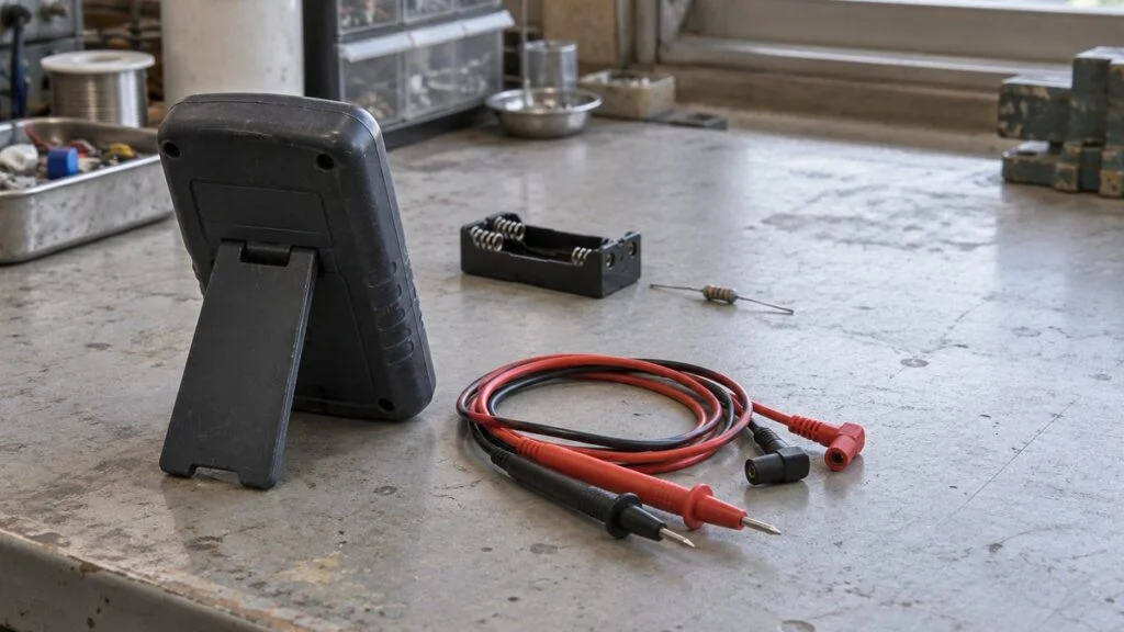
A maintenance manual from a Japanese equipment maker tells you to "check the current with a tester." In Japan, tester (テスター) is the everyday word for a multimeter, and the meter on the bench may be a Sanwa, Hioki, or Kyoritsu unit with a Japanese manual. Voltage readings are easy. Current is where people blow fuses, or worse.
The core rule is short: to measure current directly, the meter must be part of the circuit, connected in series, so the current flows through it. Touching the probes across a power source the way you would for a voltage reading, with the red lead still in a current jack, creates a short circuit through the meter.
This guide explains how a meter measures current, how to read the Japanese labels on testers and in their manuals, how jacks differ from ranges, when a clamp meter is the better tool, and what to check about fuses and measurement categories (CAT II/III/IV under IEC 61010). It describes what to check and why. It is not a work instruction: follow your meter's manual and your site's electrical safety procedures, and leave live panel work to people trained and authorized for it.
Contents
- How a Multimeter Measures Current
- Reading a Japanese Tester and Its Manual
- Series Connection, Shown on a Battery Circuit
- Reading and Recording the Value
- When a Clamp Meter Is the Better Tool
- Hazards: Parallel Connection, Over-Range, and Fuses
- Measurement Category (CAT) and Voltage Rating
- Checklist: Before Measuring Current on Japanese Equipment
- Where This Guide Does Not Apply
- FAQ
- Sources
How a Multimeter Measures Current
When a digital multimeter measures current through its input jack, the current passes through a small internal resistor called a shunt. The meter reads the voltage drop across the shunt and converts it to current using the shunt's resistance (Ohm's law).
That is why the current has to flow through the meter. "Breaking the circuit" here does not mean cutting into insulation. It means removing power, opening a connection point in the circuit, and inserting the meter there.
AC-capable digital meters convert the AC current to a voltage and then process the waveform into a displayed value such as RMS. Analog meters move a needle by a different mechanism, so not every tester works the same way inside.
Figure 1: Current Calculated from the Voltage Across a Shunt
The thick line is the current being measured; the dotted lines are the voltage-sensing connections. A simplified view of a digital multimeter.
The dotted lines go to a high-impedance voltage-sensing stage Vₛ; they do not short the shunt. Protection and range-switching circuits are omitted. There is no need to open the meter case to check any of this.
For example, if the shunt were 1 Ω and the voltage across it 10 mV, the current would be 10 mA. These are illustrative numbers only; your meter's internal resistance is not necessarily 1 Ω.
Current vs. Voltage vs. Resistance Measurement
Voltage is measured in parallel, across the two points of interest. The voltage input has a high resistance so it draws very little current from the circuit, which is the opposite of what a current input is designed to do.
For resistance, the meter supplies its own small test current. Manufacturers' manuals call for removing power from the part and discharging any stored charge before measuring, which makes resistance work very different from reading the current of an operating circuit.
Figure 2: Connection and Power State by Measurement Type
Keep apart the situations where the circuit must be de-energized and those where it is energized to take a reading. Jack labels are typical examples.
| Quantity | Red lead jack | Connection | Power state of the circuit (as typical manuals describe it) |
|---|---|---|---|
| Current (A) | A / mA / µA | In series with the circuit | Connect with power off → energize to read → power off to disconnect |
| Voltage (V) | V·Ω | In parallel, across the two points | Reads a supply voltage or a voltage in an operating circuit |
| Resistance (Ω) | V·Ω | Across an isolated component | External power removed and stored charge discharged |
The black lead goes in COM. Which jacks are shared, and for what, varies by model; check the manual.
Continuity checks, used to see whether a contact is open or closed, are resistance measurements too, and they are likewise done with the circuit de-energized.
COM, the black lead's jack, is the meter's common terminal. It does not mean the point is always at earth (ground) potential. As with COM terminals on equipment, the question is which circuit it is common to. See What Does COM Mean? Common Terminals on Japanese Equipment.
Why the Meter Changes the Current It Measures
The current input has its own internal resistance, and the leads and fuse add more. All of it ends up in series with the load, so once the meter is in, the current drops slightly and so does the voltage across the load.
The voltage that appears across the meter input because of the current flowing through it is called the burden voltage (futan den'atsu, 負担電圧 in Japanese manuals). The effect grows with low-voltage circuits and low-resistance loads.
Take an ideal 3 V source and a 100 Ω resistor: without the meter, the current is 30 mA. If the meter and leads together add 10 Ω (an assumed value), the current falls to about 27.3 mA, and about 0.273 V is lost across the meter.
The real input resistance depends on which current jack and range you use. Sanwa's manual for its CD772 meter also notes that the current range's internal resistance is inserted in series, and that the effect is larger in low-resistance circuits. Fluke publishes burden voltage as a specification for the same reason.
More display digits will not remove this error. If a device stops working, or the reading is lower than expected, once the meter is inserted, separate three possible causes: a fault in the device, the meter's voltage drop, and the effect of opening the circuit.
Reading a Japanese Tester and Its Manual
Japanese meters usually carry international symbols and abbreviations on the panel (DCA, ACA, V, Ω, COM), but the manual, the warning labels, and local work standards are often in Japanese. The terms below are the ones that matter for current measurement.
Figure 3: Japanese Terms You Will Meet in Tester Manuals
Romaji and meaning for each term. Exact wording varies by maker.
| Japanese | Romaji | Meaning |
|---|---|---|
| テスター / 回路計 | tesuta / kairokei | Multimeter. Kairokei is the formal term (the JIS term for circuit testers) |
| 直流電流 / 交流電流 | chokuryu denryu / koryu denryu | DC current / AC current (panel: DCA / ACA, or the DC and AC symbols) |
| 電流入力端子 | denryu nyuryoku tanshi | Current input jack (A, mA, µA) |
| レンジ / オートレンジ | renji / oto renji | Range / autoranging |
| 最大入力 / 最大定格 | saidai nyuryoku / saidai teikaku | Maximum input / maximum rating for a jack or function |
| 連続測定時間 / 休止時間 | renzoku sokutei jikan / kyushi jikan | Maximum continuous measuring time / required rest time (high-current input) |
| ヒューズ (指定品) | hyuzu (shiteihin) | Fuse (the specified replacement part) |
| 遮断容量 | shadan yoryo | Breaking capacity of the fuse |
| 測定カテゴリ | sokutei kategori | Measurement category (CAT II/III/IV) |
| 対地間最大定格電圧 / 端子間 | taichikan saidai teikaku den'atsu / tanshikan | Maximum rated voltage to earth / between terminals |
| 負担電圧 | futan den'atsu | Burden voltage |
| 確度 / 分解能 | kakudo / bunkaino | Accuracy / resolution |
| 真の実効値 | shin no jikkochi | True RMS |
When a term in your manual is unclear, ask the maker's distributor or the Japanese equipment supplier rather than guessing.
Check That the Meter Can Measure Current at All
Start with the manual: does the meter have a direct DC current function? Some testers measure voltage and resistance but have no current input, and some measure AC current only through a clamp probe.
DC is marked "DC" or with a solid line over a dashed line; AC is marked "AC" or with a wave symbol. On some models the same A position on the dial switches between AC and DC with a button, so check both the dial and the display.
Before connecting anything, the manual and the circuit documents should answer four questions:
- The current: DC or AC, the normal value, and the peak at startup
- The input path: which jack (A, mA, or µA) and which fuse protects it
- The limits: maximum current, continuous measuring time, rest time, and rated voltage to earth and between terminals
- The location: the measurement category of the meter, leads, and probe accessories, and the operating environment
If you do not know the current, do not connect the meter "just to see" when it could exceed the meter's maximum input. Estimate the upper limit from the schematic or equipment specifications, pick a meter that can handle it, and start on a high range.
Jacks and Ranges Are Separate Choices
The range is what the display can show; the jack is the path the current takes into the meter. Autoranging changes the display range automatically. It does not move the red lead to another jack, and it does not raise the jack's input limit.
On meters with separate low-current and high-current jacks, the internal input path and the fuse protection also differ from jack to jack. On the Sanwa CD772, for example, the µA/mA input and the A input are separate, and switching between them is manual even in autorange mode.
Figure 4: Choosing a Jack and Setting the Range Are Separate Steps
A simplified meter with two current inputs. Use the manual for your model's actual jack names and limits.
A concept diagram of separate input paths; sensing, switching, and protection circuits are omitted. Check the protection conditions for each current jack on your model.
Leaving the lead in the A jack and turning the dial to mA does not give you a proper low-current measurement. The reverse is worse: pushing a large current into the mA jack exceeds that jack's limit, no matter how wide the display range is set.
Watch the units, too. 1 A is 1,000 mA, so 0.003 A is 3 mA and 0.30 A is 300 mA. Read the unit on the display, not just the decimal point.
Moving the red lead back to the V·Ω jack after every current measurement is a habit worth building into your routine. It prevents the next user from touching a supply with the lead still in a current jack, and it is worth doing even on a meter only you use.
Series Connection, Shown on a Battery Circuit
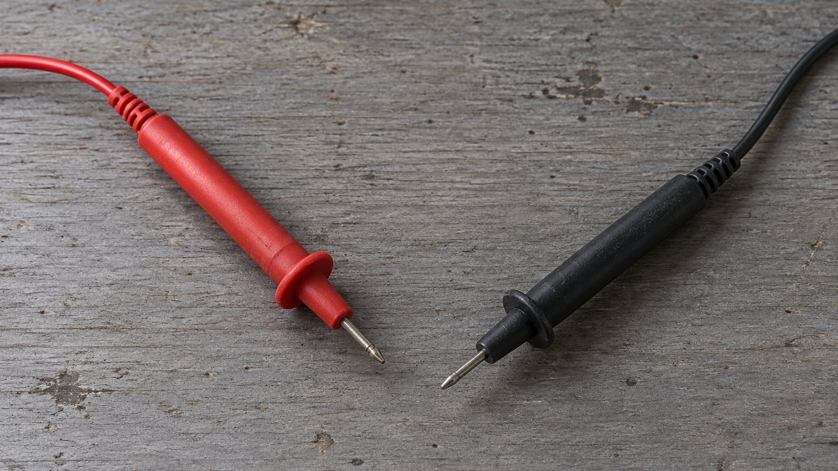
The clearest way to see a series connection is a small, low-voltage circuit: two AA cells in series (about 3 V) driving a 1 kΩ resistor rated 0.25 W or more. Every bit of current has to pass through the resistor, which limits it.
Even dry cells heat up when shorted, so the battery terminals are never connected directly to each other through the current jack. This example illustrates the concept on a low-voltage circuit where the current always passes through a load resistor. It is not a procedure for outlets or opened distribution panels.
Figure 5: The Meter Inserted in Series Between the Battery and Resistor
The connection while measuring. The circuit is assembled and taken apart with the batteries removed.
The dotted line is a rough picture of the current path inside the meter. Arrows show conventional current, which flows opposite to electron movement.
Trace the loop: battery + → resistor → red lead → meter → COM and black lead → battery −. The meter sits at one point in that loop, and there is no branch that lets current return to the battery without passing through the resistor. Hioki's manual for its 3030-01 analog tester, like the CD772 manual, describes connecting and disconnecting with the power off and energizing only to take the reading.
The expected current is about 3 mA, and the resistor dissipates about 9 mW. Battery voltage, resistor tolerance, and the meter's internal resistance will shift the actual reading, but the estimate is a quick way to catch a unit mistake.
The same principle applies when changing jacks or ranges: the manuals describe removing power first, rather than moving the plug while the circuit is live. Whether and how this is done on real equipment is set by your site's procedures, not by this article.
Reading and Recording the Value
A minus sign on a DC reading means the current is flowing opposite to the red-to-black direction. On an analog meter the needle swings backward instead, which strains the movement; the manuals call for removing power and correcting the polarity.
Record more than the number and unit. Note the measurement point, DC or AC, the function and range, and the operating state. Current right after startup differs from steady running, and readings without conditions are hard to compare later.
Mixing standby current with running current can make a normal change look like a fault. When you compare readings to spot problems, measure at the same point with the equipment in the same state.
HOLD freezes the value on the display. If a reading will not change, do not conclude that the circuit is stable. Check for the HOLD or relative-mode indicator, and return to the normal measurement display before comparing readings.
A 4–20 mA instrument signal assigns a process value to a current level. Opening that loop interrupts the signal and can change what the control system does, so plant measurements on such loops need a plan for stopping or handling the signal first. See 4-20 mA vs 1-5 V: Why Japanese Panels Use 250 Ω Inputs, and use the signal list to confirm whether you are looking at an analog current or an on/off contact (DI/DO/AI/AO signal lists).
Resolution, Accuracy, and AC Readings
Resolution is the smallest step the display can show. Accuracy is how far the reading may be from the true value. A meter that shows many digits is not guaranteed to be right in all of them.
Accuracy written as ±(% rdg + dgt) has two parts: rdg is the reading and dgt is counts of the least significant digit (the same idea as "% of reading + counts"). For example, on a hypothetical range with 0.01 mA resolution and ±(1% rdg + 2 dgt), a 3.00 mA reading has a tolerance of 0.03 mA + 0.02 mA = ±0.05 mA.
On a range that is too wide, the fixed digit term weighs more heavily on the result. That is why, once you have confirmed the input is safe, a range closer to the actual current gives better precision. Accuracy also comes with conditions such as temperature, humidity, and frequency, so it helps to log the meter's calibration date and the conditions of use.
AC current is normally read as an RMS value. For non-sinusoidal currents, check whether the meter is true RMS and what frequency range and crest factor it supports. Even a true RMS meter cannot read waveforms outside those limits correctly, so inverter (VFD) outputs need a meter and method suited to them. A normal display update can also miss short startup peaks; for inrush current, check the response specifications of the meter's max-hold or inrush-current function.
When a Clamp Meter Is the Better Tool
A clamp meter senses the magnetic field around a conductor. Because the current does not flow through the meter, you clamp over the insulation and do not need to open the circuit. Some testers have a clamp built in.
To measure load current, clamp one conductor only: the supply or the return. Clamp both together and their opposing fields cancel, so you do not read the load current.
Figure 6: Clamp One Conductor to Read Load Current
When the outgoing and return currents are equal, clamping both together gives a net field of almost zero.
Leakage current measurement is a different job: it deliberately encloses the supply and return conductors together and reads the difference. Do not mix up the two methods.
A cord with both conductors inside one jacket gives no load-current reading when clamped as a whole. Rather than slitting the jacket, use a line splitter (line separator) accessory or a measuring point that suits the equipment.
Kyoritsu's clamp meter guide sets out the main differences between models:
- AC-only clamps use a current transformer (CT) and cannot measure DC. For DC, you need an AC/DC clamp, which typically uses a Hall-effect sensor.
- DC measurement requires zero adjustment (automatic on some models).
- Jaw closure matters: jaws that do not fully close change the magnetic circuit and can cause large errors. Check the mating surfaces for dirt before clamping, and place the conductor where the maker specifies (accuracy is generally best near the center of the jaw).
- Model limits: minimum measurable current, maximum conductor size, and frequency range all come from the manual.
A few-milliamp instrument signal needs a clamp with enough resolution and accuracy for it, typically a process (milliamp) clamp. A decimal point on a high-current clamp's display does not mean it can read small signals to the accuracy you need. Fluke describes measuring 4–20 mA loops this way without opening the circuit.
For motor current on plant equipment, a clamp reading is usually the practical choice because the circuit stays closed. When you compare readings over time, keep the load condition and the phase you clamp the same.
Hazards: Parallel Connection, Over-Range, and Fuses
The most serious mistake is connecting a current jack across a power source or a load, in parallel. The meter's low internal resistance creates a path around the load, and the source drives a large current through it.
Treat this as a short-circuit incident, not just a blown fuse: it can cause heating, damaged leads, arcing, burns, and electric shock. On equipment that can deliver high power, the hazard during a fault is large even if the normal current is small.
Figure 7: A Parallel Connection Bypasses the Load and Shorts the Source
A concept diagram of a dangerous mistake. Do not try connecting a current input across a power source.
Turning the dial back to voltage does not remove the risk if the red lead is still in a current jack.
Over-Range and Reverse Polarity
A typical over-range case: a 2.5 V, 0.5 A miniature bulb measured on an analog tester with a 250 mA maximum. The needle pins, and the bulb glows dimly. This is a failure example; do not reproduce it. Since 0.5 A is 500 mA, the bulb's rated current alone is twice the meter's limit. The fix is choosing the right meter, not a different dial position.
A bulb's marking is its rating at a specified voltage. Actual current varies with the battery voltage and the filament temperature, so the rating alone is not a reason to pick a range right at the limit.
An over-range indication or a pinned needle means the power to the circuit should be removed first. Turning the dial or leaving the circuit energized adds to the risk. Review the input rating and connection, and have the meter checked before using it again.
Fuse Ratings and Measuring Time
A meter fuse is defined by more than its current rating: rated voltage, breaking capacity, time-current characteristic, and physical size all matter. Breaking capacity is the fault current the fuse can safely interrupt. It is not the current you are allowed to measure.
Replace a blown fuse with the part the maker specifies, not a store-bought fuse with the same amp rating. Bridging it with wire or fitting a higher rating removes the protection. Find out why it blew before measuring again.
Related: Circuit Protector (CP) vs. Circuit Breaker (NFB) and Fuse
High-current inputs often come with a maximum continuous measuring time and a required rest time between measurements. These limits are model-specific, so read them from your meter's manual. A jack marked with a maximum current is not rated to carry that current indefinitely; both the current and the time limits apply.
Measurement Category (CAT) and Voltage Rating
The measurement category, or CAT rating, is a safety classification defined in IEC 61010 for where in the electrical installation a meter may be used. Japan's equivalent is JIS C 1010; for example, JIS C 1010-2-30:2019, which covers equipment with testing or measuring circuits such as multimeters, is based on IEC 61010-2-030:2017 with modifications. The categories reflect how much transient energy reaches each part of the system:
- CAT II: equipment connected to receptacles (plug-in appliances and portable tools)
- CAT III: the building's distribution: distribution panels, building wiring, and fixed equipment such as switchgear and polyphase motors
- CAT IV: the source of the installation: the service entrance, utility connection, outdoor conductors, and electricity meters
Hioki's safety guidance (in Japanese) describes the same split: CAT II from the power plug to the equipment, CAT III for building wiring, and CAT IV for the service side. Select the category for the measurement location together with its voltage rating to earth. Fluke likewise notes that the category and voltage together set the transient the meter is designed to withstand.
Do not choose by "CAT III" alone. Check whether the rating is 300 V or 600 V, check the rated voltage between terminals, check the limits on the direct current input, and check that the meter body, test leads, and any accessories each meet the requirement. In the IEC 61010 family, hand-held probe assemblies are covered by IEC 61010-031 and clamp-type current sensors by IEC 61010-2-032, so leads and clamps carry their own ratings.
A larger fuse does not raise the CAT rating, and any non-specified fuse weakens the protection. The category reflects the protection design of the whole instrument and the assessment of where it is used, not the fuse's current rating.
Breakers on the equipment side (NFB/MCCB and ELB) do not make it acceptable to exceed the meter's input ratings. Measurements on utility power and control panels should follow your workplace's work standards and be planned by trained, authorized people.
Checklist: Before Measuring Current on Japanese Equipment
Use this list to confirm the meter, the location, and the plan before anyone connects a lead. Each item points to the manual, the drawings, or the person who decides.
Figure 8: Pre-Measurement Checklist
Answer every row from documents or from the responsible person, not from memory.
| Item | What to confirm | Where to find it |
|---|---|---|
| Clamp or direct? | Can a clamp meter do the job without opening the circuit? | Drawings, accessible conductors |
| Current | DC or AC, normal value, startup peak, waveform (inverter output?) | Schematic, equipment specification, nameplate |
| Meter function | Direct DC/AC current function present; true RMS if needed | Meter manual (直流電流 / 交流電流) |
| Jack and limit | A, mA, or µA jack; maximum input; continuous time and rest time | Meter manual (最大入力, 連続測定時間) |
| Fuse | Fuse intact; specified replacement part on hand | Meter manual (ヒューズ, 指定品) |
| CAT and voltage | Category and voltage to earth for the meter, leads, and clamp match the location | Meter and lead markings (測定カテゴリ, 対地間) |
| Effect of opening | Will opening the circuit stop the machine, trip an interlock, or break a 4–20 mA loop? | Equipment maker, control engineer |
| Authorization | Who is trained and authorized to work on this circuit; which procedure applies | Site electrical safety procedure |
| Afterward | Red lead back in V·Ω; reading recorded with point, mode, range, and operating state | Your own record |
This list checks preparation; it does not replace your site's procedure for working on energized or de-energized circuits.
Questions to Ask the Japanese Equipment Supplier
When a Japanese manual or work instruction says "measure the current with a tester," these questions make the instruction safe to act on:
- What is the expected current at this point (normal and at startup), and is it DC or AC?
- Is there a designated measuring point, test terminal, or clamp position, so we do not have to open the circuit?
- Does opening this circuit stop the machine, change the control output, or trip an interlock?
- Which meter type and measurement category do you assume for this location?
- Is the waveform distorted (inverter output, switching supply), so a true RMS meter or a specific clamp is needed?
- Can you send the English version of the procedure, or confirm the meaning of the Japanese terms in it?
Where This Guide Does Not Apply
Meter designs, jack names, limits, and time conditions vary by model; the CD772 and 3030-01 are mentioned only as examples, and their numbers do not carry over to other meters. Whether a measurement is allowed on an energized system, who may do it, and what protective equipment is required are set by your local regulations and your employer's procedures, which this article does not cover. High-power systems, inverter outputs, and high-voltage equipment need instruments and methods chosen for them.
FAQ
Can I measure a battery's current by touching the meter to its terminals?
No. Connecting a current input directly across the battery shorts it. Measure the battery's voltage with the voltage function. To find the current a load draws, put the meter in series with that load.
What should I check when the current reading is zero?
With the circuit de-energized, check the input jack, the selected function, loose connections, and the fuse, following the inspection steps in the manual. The current may also be below the resolution, or the unit may be misread, so a zero alone does not prove an open circuit.
Why does my multimeter read voltage but not current?
The current input usually has its own fuse, separate from the voltage input, and it may be blown. The lead may be in the wrong jack, or the meter may have no direct current function. A working voltage reading says nothing about the current path, so check it against the manual.
Can a clamp meter measure both AC and DC?
Only if it is an AC/DC model. AC-only clamps use a current transformer and cannot read DC, such as battery current. For DC, choose an AC/DC clamp, zero it before measuring, and check that its resolution and accuracy are good enough.
Why does the circuit stop working when I insert the meter?
Possible causes include the voltage drop across the meter and leads (burden voltage), a blown fuse, and a poor contact. Remove power before checking the input path rather than probing jacks on a live circuit, and consider a method that does not open the circuit, such as a clamp.
Sources
- Series connection, input paths, internal resistance, time limits, specified fuses: Sanwa Electric Instrument, CD772 instruction manual (Japanese)
- Burden voltage and its effect on the circuit: Fluke, "Can you live with the burden?"
- rdg/dgt and accuracy calculation: Hioki, "Calculating instrument accuracy"
- Connecting with power off, disconnecting to change ranges, analog current measurement: Hioki, 3030-01 instruction manual (Japanese)
- Measurement categories and rated voltages to earth and between terminals: Hioki, "For safe use" (Japanese)
- Measurement categories and voltage ratings under IEC 61010: Fluke, "Electrical safety standards"
- JIS C 1010-2-30:2019 and its basis in IEC 61010-2-030:2017: Japanese Standards Association, JIS C 1010-2-30:2019 preview (Japanese)
- Scope of IEC 61010-031 (probe assemblies) and IEC 61010-2-032 (current sensors): BSI, EN/IEC 61010-031 summary
- Series insertion vs. clamping, clamping one conductor: Hioki, "How to use clamp meters" (Japanese)
- Clamp sensor types, DC capability, zero adjustment, jaw closure: Kyoritsu Electrical Instruments, clamp meter guidebook (Japanese)
- Measuring 4–20 mA signals without opening the loop: Fluke, "How to measure a 4-20mA loop signal"
Original article in JapaneseThis guide is adapted from a MONOSCOPE article written for readers in Japan: テスターで電流を測る方法|直列接続と端子・レンジ選び、短絡を防ぐ手順
About the editor
 MONOSCOPE EditorFOUNDER & EDITOR
Spent about ten years at a plant equipment maker and a plant engineering company, proposing, designing, and commissioning equipment, then moved into web marketing. Now a web consultant for B2B manufacturers, helping them explain their products and technology. Licensed in Japan as an Energy Manager and a Third-Class Chief Electrical Engineer.
Has run an engineering blog since 2017 (500+ articles) and a Japanese YouTube channel with about 20,000 subscribers. Each English guide is written from the Japanese shop-floor point of view and checked against the cited standards.