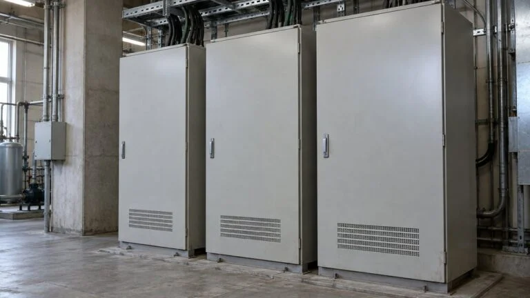
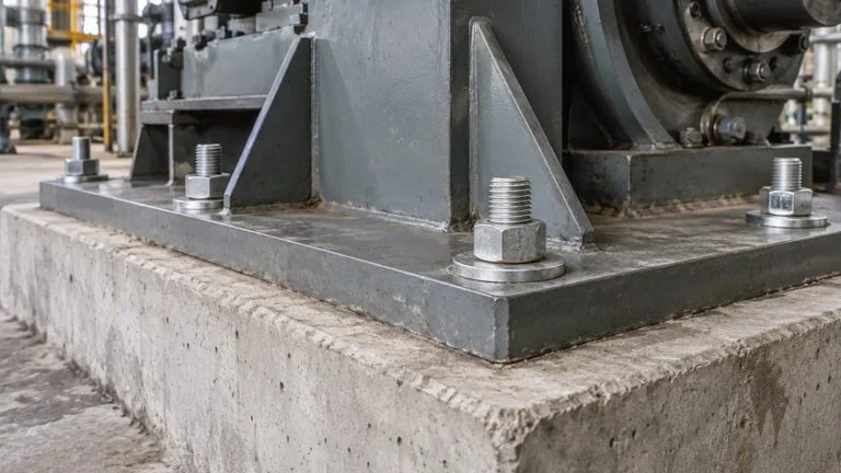
Equipment Loading Data for Foundations: What to Submit, When
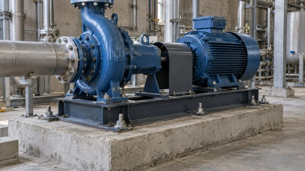
Imagine this: the document list in a Japanese purchase specification asks the pump vendor for "ローディングデータ" (loading data). The vendor sends a one-line weight table. Your civil team says it cannot start the foundation design with that, and the Japanese engineering contractor wants the foundation drawings frozen next month. This guide explains what loading data is, what it should contain, and when it is due, so you can ask for the right information the first time.
In short: loading data is the design document that tells the people designing the foundation, steel frame, or building floor what loads a piece of equipment puts on them. Besides weights, it shows the center of gravity, the support points, the direction of each force, and the operating conditions behind each value. A weight list alone is often not enough, because two machines of the same weight can load a foundation very differently if their center of gravity or support arrangement differs.
Contents
What Is Loading Data?
Loading data organizes a piece of equipment's weight, center of gravity, dimensions, and operating forces in a form the foundation designer can use. Japanese documents may also call it 機器荷重図 (kiki kaju-zu, equipment load drawing) or 基礎荷重資料 (kiso kaju shiryo, foundation load data), so agree with the purchaser on what the document must contain rather than relying on the name.
It applies to any equipment that transfers load into a structure: pumps, tanks, compressors, turbines, and various support frames. "Equipment that needs a foundation" also includes equipment supported on a building floor or a steel frame, so the absence of a standalone concrete foundation does not by itself mean loading data is unnecessary. Whether the equipment sits on its own foundation, a floor slab, or a frame also changes who receives the data and which conditions they need.
Which items to include depends on the equipment and the order conditions. Information on anchor bolt locations and embedment, in particular, is settled by agreeing on who is responsible for what on the equipment side and the foundation side, and then checking that both sides match.
Figure 1: Weight, Center of Gravity, and Support Points in One Coordinate System
Schematic for explanation only. Fix one coordinate convention so the reader can find the center of gravity and the point where each load acts.
What Loading Data Should Include
Equipment Identification and Scope
Start by making clear which equipment the document covers. Show the equipment tag, model, quantity, and scope of accessories on the drawing, and state whether a weight is for the machine alone or includes the motor and common baseplate.
Weights by Condition
Weight changes with the condition of the equipment: empty (dry), operating, filled with liquid, under test, and so on. Do not mix values for the machine alone with values that include contents, insulation, or accessories, and label every number with the condition it represents.
Figure 2: Pair Each Load Case With What It Includes
Example layout. If liquid remains in the equipment when it is stopped, show that separately from the dry condition. The cases you need depend on the equipment, the location, and the design conditions. Do not simply add up maximum values from cases that cannot occur at the same time.
Mass vs. Force, Static vs. Dynamic
"Running vs. stopped" and "static vs. dynamic" are different classifications. Self-weight and the weight of the contents are static components even while the machine runs. Keep them separate from forces that vary with startup and shutdown, vibration, or rotating and reciprocating motion.
"Mass 2,500 kg" and "vertical load 24.5 kN" also describe different physical quantities in different units. State whether each value is a mass or a force converted from mass, and never hand over a table of bare numbers labeled only "weight."
Center of Gravity, Support Points, and Coordinates
Next, show the center of gravity and the support points through which the load enters the foundation. Overall dimensions do not tell you where the center of gravity is, and assuming it sits at the middle of the machine has to be checked against the configuration that will actually be delivered.
The height of the center of gravity also governs the overturning moment that horizontal forces create. A Japanese Ministry of Agriculture, Forestry and Fisheries (MAFF) document on installing electrical equipment, for example, shows a foundation check that uses the equipment weight, center-of-gravity height, and bolt spacing.
Put the coordinate origin at a point that can be identified on the drawing, such as the center of the equipment, a defined point on the edge of the baseplate, or a reference support point. Align the X, Y, and Z directions and the dimensional reference planes so the foundation designer is less likely to make mistakes when converting to a different origin. Dimensions should be traceable from the same reference points as the physical equipment: show the distances between support points and the heights above the reference plane, and make the center of gravity readable on the same drawing as the outline.
Related: How to Read Japanese Engineering Drawings (JIS B 0001)
If you tabulate forces and moments, state the positive direction of each component. "The force the equipment applies to the foundation" and "the reaction the foundation provides to the equipment" point in opposite directions, so make it clear which one the table shows.
If the point where loads are summed differs from the point the foundation designer calculates at, share that offset too. The same horizontal force creates a different moment at a different height, so keep each value and its point of application in the same document.
Seismic, Wind, and Dynamic Loads
For seismic, wind, and similar actions, the equipment manufacturer and the civil/structural side need to agree who calculates what. Separate what the receiving side will calculate from the weight and center of gravity and what the manufacturer has already calculated, so the same action is not applied twice.
For rotating machinery, the foundation designer may need the speed or frequency and the direction of the vibrating force, not just its magnitude. Check whether a table of static loads is enough, and if dynamic data is needed, ask the manufacturer for it specifically.
A value labeled only "dynamic load," for example, could be a force that varies with time or a static load with an allowance added. Confirm the definition of the value, the direction in which it varies, the frequency information needed, and which calculation it is meant for.
Piping Loads and Allowable Nozzle Loads
Piping loads acting on the equipment nozzles are a separate item to check. KSB's planning information covers the weight of the pump and its contents as well as the weight of the piping and the liquid in it, and it explains that forces from thermal expansion and pressure must also be considered, depending on how the piping is supported.
An "allowable nozzle load" is the range of force the equipment can accept at its nozzles. Do not read it as a load that the equipment continuously transmits to the foundation. Instead, compare the piping loads that actually act on the nozzles with the supports that will carry them.
Depending on the equipment, allowable displacement and installation accuracy can also be conditions the foundation designer needs. Keeping in mind how expansion joints differ from flexible hoses, distinguish the parts that move with thermal expansion from the fixed points, and share who carries the forces created where movement is restrained.
Worked Example: Why Total Weight Is Not Enough
To see what support reactions mean, take a simple model with two support points. The equipment has a dry mass of 1,500 kg and holds 1,000 kg of liquid, so its operating mass is 2,500 kg (about 5,510 lb). For illustration, use a gravitational acceleration of 9.8 m/s².
Figure 3: Same 24.5 kN, Unequal Reactions When the Center of Gravity Is Off-Center
A model with two supports carrying vertical load only. This figure alone cannot determine the load on each leg of a real four-legged unit or on its anchor bolts.
Let supports A and B be 2.0 m apart, with the center of gravity 0.8 m from A. Taking moments about A gives the reaction at B, and A carries the rest of the vertical force.
Splitting the load evenly, 12.25 kN at each support, would give the wrong values here. The total weight does not tell the designer what each support must carry, which is exactly why the center of gravity and the support locations are needed.
On a real skid, the number of supports, their stiffness, the fixing method, horizontal forces, and moments also come into play. The two-support example only shows what the information means. It is not a formula for sizing anchor bolts or foundations.
Why Loading Data Matters: Who Passes What to Whom
Loading data connects the people who select the equipment with the people who design the structure that supports it. Even when the equipment's capacity and connections are fixed, the design basis for the foundation or frame is incomplete until the loads at the supports are known.
On some Japanese projects, the plant (process equipment) work and the building/civil work are let under separate contracts, known as 分離発注 (bunri hatchu). When they do, the equipment manufacturer's design conditions must be passed to the building side. One common arrangement: the plant side coordinates equipment selection and layout, and the civil/building side designs the structure from the conditions it receives.
Figure 4: From Equipment Drawings and Load Tables to the Foundation Design Basis
Example of a handover under separate contracts. Do not just forward documents: check that they match the equipment and layout that will actually be delivered.
Write the requirements for the manufacturer into the purchase specification (購買仕様書, kobai shiyosho). Listing the required load cases, format, submission date, and how revisions will be notified, not just the document name, reduces misunderstandings later.
Related: Equipment Purchase Specification: Items, Checks, Template
The plant side checks the equipment tags in the manufacturer's documents against the layout drawings and the piping and accessory conditions. When it receives a reference drawing for the same product series, it also checks that the delivered model, motor, and baseplate are reflected.
When passing the data to the civil/building side, tie each load to the location and height of its support. If the installation floor or foundation location changes, the structural conditions change even at the same weight, so manage layout and loads as a pair.
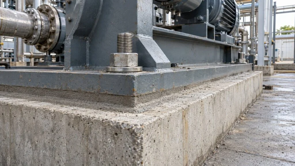
Anchor bolt hole locations, baseplate dimensions on the equipment side, and anchorage conditions on the foundation side must all agree. Whether the anchors are cast-in or post-installed also matters, but do not judge the embedment length or the foundation's suitability from the hole diameter on the equipment drawing alone.
When equipment is fixed to a steel frame instead of a concrete foundation, connection details are needed. Match the fixing method you adopt, such as a tapped plate, to the conditions of the members and connections that will take the force.
Equipment-side conditions such as allowable displacement and vibration tell the structural side what performance the structure must provide. Conversely, if the support conditions or foundation stiffness differ from what the equipment design assumed, the equipment-side assessment may have to be redone.
State whether each value is an actual (unfactored) load or a design value that already includes allowances or load factors. A verbal "we rounded it up to be safe" does not stop the receiving side from applying its own factors on top.
At the quotation stage in particular, some equipment and accessories are not yet fixed, so design may proceed on approximate values. If it does, record the margin assumed, what it covers, and the deadline for firm values, so there is a record of what the early design was based on.
Listing exclusions also helps prevent loads from being missed between the equipment side and the foundation side. For piping, insulation, access platforms, and cable equipment added on site, decide whether they belong in the equipment data or are totaled separately.
A heavier assumed weight is not always on the safe side. For uplift and overturning checks, the lighter condition can govern. Share both maximum and minimum values and the conditions under which each case applies.
Preparing the data, acknowledging receipt, and approving it for design are three different things. With the way approval-returned drawings are handled in mind, keep track of who has checked which conditions and which items are still open. For how Japanese approval drawings are reviewed and returned, see Approval Drawings (Shonin-zu) in Japan.
Beyond getting the format right, give the reader references they can check. Align the drawing numbers and revisions of the outline drawing, the foundation drawing, and the load table, and make clear which documents go together.
When several items of equipment share one frame, consider which operating states occur at the same time, not just each item's maximum. Agree on the combinations needed (normal operation, switchover to a standby unit, testing, maintenance) and feed them into the design conditions for the frame as a whole.
When to Submit Loading Data
As a baseline, loading data is due before the conditions are entered into the structural design of the foundation or building. If final data arrives just before equipment delivery, when foundation work or building design is already under way, any change has a much bigger impact.
Plant construction can be seen as a sequence: basic planning, mechanical design, building and foundation design, foundation work, building work, equipment installation, then piping and electrical work. In practice, design runs in parallel, so you cannot wait until every equipment detail is final before submitting data.
Figure 5: Match Preliminary Data, Final Data, and Change Notices to Project Milestones
Work backward from the receiving side's design and construction milestones rather than a fixed number of days. Even after construction starts, do not let a change sit: share its impact and the response with everyone involved.
Basic planning. Approximate dimensions and weights of candidate equipment may be used for layout and floor-load studies. Even though this is not yet formal loading data, mark the values as provisional and list the excluded scope on the drawing or list.
Quotation. Align conditions through the quotation specification (見積仕様書, mitsumori shiyosho). Identify which items could change the loads after the order and which need to be coordinated with the receiving side early.
Related: Quotation Specification (Mitsumori Shiyosho): Sample Format
Order. Tie the submission deadline in the purchase specification to the schedule. Instead of a vague "submit after order," agree on a date that works for finalizing the foundation drawings and planning the anchor work.
Vendor's final data. When the formal equipment drawings and load conditions arrive, compare them with the earlier data. Check weight, center of gravity, support points, outline, and accessories, and pass any differences to the foundation side.
Final scope. Manage the final scope of supply against the delivery specification (納入仕様書, nonyu shiyosho). If only the load table is current while the outline or layout drawings the foundation designer uses are an older revision, the conditions still conflict. See Delivery Specification (Nonyu Shiyosho): What to Check.
Handling Changes and Queries
A change notice should say not only what changed but also what it affects. An increase in mass affects the loads at the supports, and a shift in the center of gravity affects the reactions and overturning. A change in hole locations needs a check against the anchors. Present each change so the receiving side can follow it.
Replacing a drawing does not always get the change to the people doing the work. Confirm who received it, which drawings need updating, the current construction status, and whether the change affects anchors or fabricated parts already ordered.
When the receiving side sends a query, answer by stating which value in the load table is being reviewed and under what conditions. Do not settle it verbally: reflect the answer in the necessary revision so the answer and the drawings agree.
If a change comes to light after the foundation is built, you cannot simply set the numbers back to the old values and tidy up the paperwork. Show the actual equipment conditions and the as-built state, and decide with the receiving side's designer what re-evaluation or action is needed.
The final turnover package should let anyone trace the confirmed conditions and the revision history. Being able to look up the original weights, support points, and operating conditions helps when existing equipment is evaluated for future replacement or expansion.
Loading Data Review Checklist
Use this list when you receive loading data from a Japanese supplier, or before you pass it on to the foundation designer. Checking the items in order catches most basic gaps.
- Tag and quantity: equipment tag, model, and number of units match the layout and the order
- Scope: whether each weight includes the motor, baseplate, and accessories
- Weights by condition: empty, operating, filled/test, and maintenance values, each labeled
- Mass or force: kg vs. kN stated for every value
- Center of gravity: located in X, Y, and Z, including height
- Support points: locations, and loads or reactions at each point
- Coordinates and units: origin, axis directions, sign convention, reference plane
- Actual vs. allowable: actual loads kept separate from allowable values such as nozzle loads
- Dynamic data: definition of any "dynamic load," plus speed/frequency and direction where needed
- Seismic and wind: who calculates them, and whether supplied values already include them
- Factors and margins: whether values are unfactored or include allowances or load factors
- Minimum case: lightest condition available for uplift and overturning checks
- Open items: provisional values, exclusions, and the date they will be confirmed
- Related drawings: drawing numbers and revisions of outline, foundation, and anchor drawings
Questions to Ask the Japanese Supplier
- Which conditions do the weights in this table represent (empty, operating, test, maintenance), and what does each include?
- Are these values mass (kg) or force (kN)? Are they actual loads or design values with factors or margins included?
- Where is the center of gravity, including its height, and from which origin and reference plane is it measured?
- What are the loads at each support point, and what is the sign convention?
- Does the "dynamic load" value vary with time, or is it a static load with an allowance? What speed or frequency applies?
- Do these values already include seismic or wind loads, or should our structural team calculate them?
- Are the nozzle loads shown actual piping loads or allowable values?
- Which items are still provisional, and when will final values be issued?
- Which outline and anchor drawing revisions does this load table correspond to?
Sample Request Email
Edit the bracketed parts to fit your project.
Subject: Loading data for [tag no.] – information needed for foundation design
Thank you for the weight table for [tag no.]. To start the foundation design, our structural team needs the following:
1. Weights for each condition (empty, operating, test, maintenance), with what each includes
2. Center of gravity in X, Y, and Z, with the origin and axis directions
3. Loads at each support point, with the sign convention
4. Whether the values are unfactored, and whether seismic or wind loads are included
5. Dynamic data for the rotating equipment (speed, magnitude, direction), if applicable
6. Any provisional values and the date final values will be issuedOur foundation drawings are scheduled to be finalized on [date], so we would appreciate the data by [date]. Please also tell us which outline drawing revision the data is based on.
Limits of This Guide
What loading data must contain, what it is called, and who prepares it vary by company, industry, contract, and project. The load cases you need depend on the equipment, the installation site, and the design conditions, and the applicable codes for seismic and wind loads depend on the country and project. The two-support calculation above is only an illustration. Foundation, frame, and anchor design must be done and checked by the responsible structural engineer under the project's design basis.
FAQ
Can I Prepare Loading Data From the Equipment Weight Alone?
No. Along with weight, provide what the receiving side needs: the condition each value represents, center of gravity, support points, and force directions. Equipment of the same weight can produce different reactions and overturning conditions, so a weight table alone is not complete loading data.
Who Prepares Loading Data, and Who Receives It?
In one common arrangement, the equipment manufacturer provides the equipment conditions, and the plant side checks them against the layout and passes them to the civil/building side. Decide who coordinates and who calculates or checks what based on the contract and the division of design work.
Is the Weight When Stopped the Same as the Static Load?
No. Running and stopped describe the state of the equipment, while static and dynamic describe the nature of the force. Present self-weight and the weight of the contents during operation separately from forces that vary with startup, shutdown, or vibration.
Is It Safe to Use Large Loads at the Quotation Stage?
Not automatically. Stating the margin in provisional values is useful, but inflating everything does not make the design safe: the lighter case can govern some checks, and factors can end up applied twice. Share the load cases and what each value represents.
If the Equipment Changes but the Weight Stays the Same, Do I Need to Resubmit?
Yes, if the change affects the foundation. Changes in the center of gravity, support points, outline, anchor locations, or dynamic forces affect the foundation even at the same weight. Compare the changes and send updated data covering every condition that affects the foundation side.
Sources
- Forces and torques transmitted to the foundation, and vibration: KSB, "Pump Foundation"
- Weights of equipment and piping, and forces from heat and pressure: KSB, "Planning Information for Tubular Casing Pumps"
- Piping loads and allowable equipment loads: KSB GIW, "Is Your Piping Stressing Your Pump?"
- Coordination with building work and a foundation check using center of gravity: Ministry of Agriculture, Forestry and Fisheries, "Installation and Wiring of Equipment" (Japanese)
Original article in JapaneseThis guide is adapted from a MONOSCOPE article written for readers in Japan: ローディングデータとは?記載項目・作成の目的と基礎設計へ提出する時期
About the editor
 MONOSCOPE EditorFOUNDER & EDITOR
Spent about ten years at a plant equipment maker and a plant engineering company, proposing, designing, and commissioning equipment, then moved into web marketing. Now a web consultant for B2B manufacturers, helping them explain their products and technology. Licensed in Japan as an Energy Manager and a Third-Class Chief Electrical Engineer.
Has run an engineering blog since 2017 (500+ articles) and a Japanese YouTube channel with about 20,000 subscribers. Each English guide is written from the Japanese shop-floor point of view and checked against the cited standards.