Flat Face vs Raised Face Flange: JIS FF/RF and ASME Guide
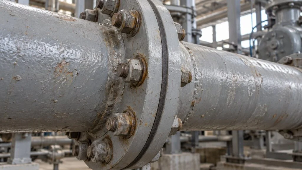
A pump skid arrives from Japan, and the nozzle schedule reads "JIS 10K 100A FF." Your site piping spec calls for ASME B16.5 Class 150 RF flanges, and the pump casing is cast iron. Two questions come up at once: can a flat-face (FF) flange be bolted to a raised-face (RF) flange, and what gasket goes between them?
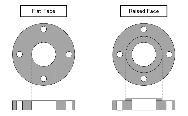
The short answer: match FF to FF and RF to RF, and do not bolt a raised-face steel flange to a flat-face cast iron flange; make the steel side flat face instead. FF and RF describe the shape of the gasket face. FF is flat all the way to the outer edge. RF has a raised ring inside the bolt holes. The facing also decides which gasket you need, so check the facing and the material of the mating flange before you order anything.
This guide covers how Japanese drawings name the two facings, how JIS B 2220 and ASME B16.5 facings differ, which combinations are acceptable, a JIS 10K gasket table, and a checklist and question list you can send to the Japanese supplier.
The difference is how much of the flange the gasket touches. An RF flange concentrates the bolt load on a narrow ring.
"Status in JIS B 2220" follows the notes in the JIS B 2220:2012 dimension tables as reproduced in the Nichias gasket catalog. "Typical service" is general practice, not a requirement of the standard.
Contents
- How Japanese Drawings Name FF and RF
- Flat Face (FF)
- Raised Face (RF)
- Can You Connect an FF Flange to an RF Flange?
- Connecting JIS FF/RF Flanges to ASME Piping
- Quick Reference: JIS 10K Facing and Gasket Dimensions
- Gasket Contact Area and Stress: A Worked Example
- Other Flange Facings: MF, TG, and RJ
- Checklist Before You Order Flanges and Gaskets
- Limits of This Guide
- FAQ
- Sources
How Japanese Drawings Name FF and RF
Japanese drawings and data sheets usually write the standard, pressure class, size, and facing in one string. "JIS 10K 100A FF" means a JIS B 2220 flange, nominal pressure class 10K, nominal size 100A (NPS 4), with a flat face. "K" is the JIS nominal pressure class (yobi-atsuryoku, 呼び圧力), and "A" is the millimeter-based nominal size.
The Japanese names are easy to misread. JIS calls FF 全面座 (zenmen-za, "full-face seat") and RF 平面座 (heimen-za). Although heimen means "flat surface," 平面座 is the JIS name for the raised face, not the flat one. The JIS tables list two raised-face sizes, 大平面座 (dai-heimen-za, large raised face) and 小平面座 (sho-heimen-za, small raised face). Plain "RF" normally means the large one.
You will also see the facing combined with the flange type, as in "SOFF" or "SORF" (slip-on, flat face or raised face) and "WN" for weld neck. Refineries and petrochemical plants in Japan often write the JPI standard and class instead, as in "JPI 150 RF."
The kanji you may see in a nozzle schedule or valve data sheet, and what they mean.
| Written on drawing | Reading | Meaning |
|---|---|---|
| 全面座 | zenmen-za | Flat face (FF) |
| 平面座/大平面座 | heimen-za / dai-heimen-za | Raised face (RF), the standard (large) size |
| 小平面座 | sho-heimen-za | Small raised face (reference annex of JIS B 2220) |
| はめ込み形 | hamekomi-gata | Male and female (MF) |
| 溝形 | mizo-gata | Tongue and groove (TG) |
| 全面形ガスケット | zenmen-gata gasuketto | Full-face gasket |
| リング形ガスケット (内パッキン) | ringu-gata (uchi-pakkin) | Ring gasket ("inner packing") |
In Japanese shop talk, gaskets are often called パッキン (pakkin, "packing"), so an RF gasket may appear as "RFパッキン" and a full-face gasket as "FFパッキン."
Flat Face (FF)
A flat-face flange is machined flat across its entire gasket face. In Japan, FF flanges are mainly used in the lower pressure classes, such as JIS 5K and 10K and JPI Class 150 and 300.
JIS 5K and 10K flanges are drawn as flat face in the standard's dimension tables. The Nichias catalog's JIS tables add a note for 5K and 10K that a raised face may be used when needed. JIS 16K and 20K flanges can be made flat face in sizes up to 600A.
Because the gasket seats over a wider area, the same bolt load produces lower gasket stress than on an RF flange. That is why FF flanges are common for non-hazardous fluids such as water and air.
Under JIS practice, an FF flange can take either a full-face gasket with bolt holes or a ring gasket that sits inside the bolts. Nichias lists its JIS ring gasket table as fitting both flat faces and large raised faces. Full-face gaskets spread the bolt load over a large area, and Nichias notes that full-face compressed sheet and PTFE gaskets make gas tightness difficult, even at 10K and 16K. US sources such as Project Materials, by contrast, pair FF flanges with full-face gaskets, and that is the combination US guidance calls for when the mating flange is cast iron (see below).
Related: JIS vs ASME (ANSI) vs JPI Flanges: How to Match Them
Raised Face (RF)
A raised-face flange has a flat, raised ring inside the bolt circle. When you tighten the bolts, the load goes into that narrow ring, so gasket stress is higher than on an FF flange and the joint seals more readily. RF flanges are therefore common for hazardous and high-temperature fluids.
Steel flanges made to ASME B16.5 are usually supplied RF, and you normally have to specify FF on the order if you need it. In JIS, RF is the standard facing for 16K and above. For 30K and above, Nichias recommends semi-metallic gaskets, such as spiral-wound gaskets, rather than sheet gaskets.
The raised-face height differs between the two standards, as Figure 3 shows. JIS B 2220 sets it by size and class, while ASME B16.5 sets it by class only.
Both standards use the same facing types, but the default facing and the raised-face height differ.
| JIS B 2220 (steel pipe flanges) | ASME B16.5 (pipe flanges, NPS 1/2–24) | |
|---|---|---|
| Default facing | FF for 5K and 10K; RF for 16K and above | Steel flanges are usually supplied RF; FF must be specified on the order |
| RF height | 1–5 mm by size and class. 10K: 1 mm (25A and below), 2 mm (32A–250A), 3 mm (300A and above). 16K and 20K at 650A and above: 5 mm | 1.6 mm (1/16 in) for Class 150 and 300; 6.4 mm (1/4 in) for Class 400 and above |
| RF in flange thickness | Confirm with the supplier | Class 150 and 300: excluded. Class 400 and above: included |
| Other facings | Small raised face (annex), male-female, tongue-groove | Male-female, tongue-groove, ring joint |
| Gasket dimensions | JIS B 2404 | ASME B16.21 (nonmetallic flat gaskets) |
JIS values from the JIS B 2220:2012 tables as reproduced in the Nichias catalog. ASME values from the 2020 edition as summarized by Project Materials. Even when the facing matches, JIS and ASME flanges have different bolt circles and do not bolt together directly.
RF flanges have one serious drawback. When the mating valve is made of a brittle material such as cast iron, tightening the bolts against a raised face bends the valve flange and can crack it. For this reason, RF is rarely used against cast iron valves. The next section explains how the crack forms and what to do about it.
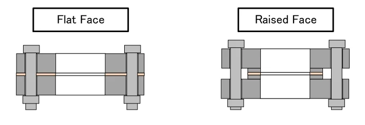
As the cross sections show, an FF joint clamps a full-face gasket across the bolt holes, while an RF joint clamps a ring gasket on the raised ring only. Because the gasket shapes differ, always state the facing when you order gaskets.
Can You Connect an FF Flange to an RF Flange?
As a rule, no. Pair FF with FF and RF with RF, so the bolt load presses evenly on the gasket. Before you decide, check four things:
- The facing of the mating flange (FF or RF)
- The material of the mating flange (steel, or cast iron or plastic)
- The standard and pressure class (JIS 10K, JPI 150, ASME Class 150, and so on), and whether the bolt holes line up
- The gasket type (ring or full-face)
In practice, some pumps and valves come only with FF flanges, so the piping side often has to match the equipment. Here is how each combination is treated.
The question is not whether the bolts can be tightened, but whether the gasket is pressed evenly.
MIRAIZ, a Japanese piping and equipment supplier, also lists a full-face gasket on an RF flange as a combination not to use.
If you put a full-face gasket on an RF flange, the part of the gasket outside the raised ring never touches the mating flange and is not compressed. Only the part on the raised ring seals, so it works no better than a ring gasket, and the outer part does nothing.
Between two steel flanges at low pressure, an FF-to-RF joint may not leak. Even then, the bolt load goes into the raised ring, and the outer edge of the FF flange is left unsupported.
In new designs, match the facings. When you find mixed facings on an existing line, check with the designer or the manufacturer. Above all, do not simply bolt up a joint where the mating flange is cast iron or plastic.
Why Cast Iron FF Flanges Crack Against Steel RF Flanges
Only the raised face touches the gasket, leaving a gap around the bolts. The more you tighten, the more the cast iron flange bends.
Schematic of the upper half of the joint. The dashed outline is the ring gasket; the shaded area is the raised face.
The risky case is a cast iron valve with FF flanges bolted to a steel RF flange. Only the raised face bears on the gasket, so a gap remains around the bolts.
As you tighten the bolts, the outer part of the cast iron flange is pulled into that gap. Cast iron tends to fracture before it bends, so a crack starts at the root of the flange.
Milwaukee Valve, a US valve manufacturer, describes a returned flat-face cast iron valve that cracked after it was mounted to a raised-face steel flange. The company states that ASME B16.5 and B31.1 both say the steel flange should have a flat face in this situation, and advises removing the raised face and using a full-face gasket. US Coast Guard rules for marine piping (46 CFR 56.25-10) say the same: when Class 150 steel flanges are bolted to flat-face cast iron flanges, the steel flange must be flat face. For the exact code wording, check the current editions of ASME B16.5 and B31.1 or the code that applies to your project.
The usual fixes are:
- Make the companion flange on the piping side a steel FF flange (for example, JIS 10K FF)
- Machine the raised face off the existing steel flange to make it FF, and use a full-face gasket
- Tighten the bolts gradually and evenly in a crisscross pattern so one side of the cast iron flange is not pulled down first
Whether you may machine off a raised face is a decision for the piping specification. Confirm it with the flange or equipment manufacturer as well. For ASME B16.5 Class 150 and 300, the flange thickness is measured without the raised face; for JIS flanges, ask the supplier.
Related: Mating Flange (Companion Flange): Who Supplies It?
Connecting JIS FF/RF Flanges to ASME Piping
Matching the facing solves only half the problem on a mixed JIS and ASME project. JIS B 2220 and ASME B16.5 flanges have different bolt circles, so a JIS 10K FF flange will not bolt to an ASME Class 150 FF flange either. At 100A (NPS 4), for example, the JIS 10K bolt circle is 175 mm, while the ASME Class 150 bolt circle is 7.50 in (190.5 mm).
The usual approach is to use a companion flange made to the equipment's standard, class, and facing, so a JIS 10K FF nozzle gets a JIS 10K FF companion flange, with a gasket sized to JIS B 2404. Where the line changes from JIS to ASME is a decision for the piping designer and the project specification.
Gaskets do not cross over either. JIS gaskets are sized to JIS B 2404, and ASME nonmetallic flat gaskets to ASME B16.21. A ring gasket for a JIS 10K flange will not center correctly on an ASME flange, because its OD is set by the JIS bolt circle (see the next section).
Quick Reference: JIS 10K Facing and Gasket Dimensions
The table below covers seven common JIS 10K sizes for steel pipe flanges. It lists the raised-face dimensions and the gasket ID and OD in millimeters. Both the ring gasket (often called an "RF packing" in Japan) and the full-face gasket for FF flanges are sized in JIS B 2404 (dimensions of gaskets for use with pipe flanges).
The ring gasket OD equals the bolt circle minus the bolt diameter, so the ring fits just inside the bolts.
| Nominal size | RF diameter g / height f | Ring gasket (RF) ID × OD | Full-face gasket (FF) OD | Bolt circle; holes (no. × dia.) | Bolt |
|---|---|---|---|---|---|
| 15A (NPS 1/2) | 51 / 1 | 22 × 58 | 95 | 70; 4 × 15 | M12 |
| 25A (NPS 1) | 67 / 1 | 35 × 74 | 125 | 90; 4 × 19 | M16 |
| 50A (NPS 2) | 96 / 2 | 61 × 104 | 155 | 120; 4 × 19 | M16 |
| 80A (NPS 3) | 126 / 2 | 90 × 134 | 185 | 150; 8 × 19 | M16 |
| 100A (NPS 4) | 151 / 2 | 115 × 159 | 210 | 175; 8 × 19 | M16 |
| 150A (NPS 6) | 212 / 2 | 167 × 220 | 280 | 240; 8 × 23 | M20 |
| 200A (NPS 8) | 262 / 2 | 218 × 270 | 330 | 290; 12 × 23 | M20 |
All dimensions in mm. g is the raised-face OD and f is its height. Extracted from the JIS B 2220:2012 (steel pipe flanges) and JIS B 2404:2018 (gasket dimensions) tables in the Nichias gasket catalog. The full-face gasket ID equals the ring gasket ID, and its OD equals the flange OD. Before ordering, confirm the mating flange's standard and pressure class and check the gasket maker's current dimension table.
At 100A, for example, the 175 mm bolt circle minus the 16 mm (M16) bolt diameter gives 159 mm, which is the ring gasket OD. All seven sizes in the table follow this rule.
Because the ring OD touches the bolts, the bolts center the gasket as you tighten, and it is less likely to shift. That is why the ring OD is slightly larger than the raised-face OD (151 mm at 100A).
A full-face gasket has the same OD as the flange and its own bolt holes, so the holes set its position and it is easy to install, but it is mainly for low pressure. The JIS B 2404 full-face tables go up to 2K, 5K, 10K, and 16K only, with no 20K or higher column.
The gasket OD also changes with the pressure class at the same nominal size. A 100A ring gasket is 149 mm OD for 5K, 159 mm for 10K, and 165 mm for 20K.
When you order gaskets, specify the standard, pressure class, and nominal size, plus the type (ring or full-face), material, and thickness. "JIS 10K 100A" alone does not tell the supplier whether you need an FF or an RF gasket.
Gasket Contact Area and Stress: A Worked Example
RF flanges seal more readily because the same bolt load acts on a smaller area. Using JIS 10K 100A dimensions, here is how the compressed gasket area compares.
With an assumed total bolt load of 100 kN, average gasket stress on the RF flange is about three times that of an FF flange with a full-face gasket.
Average gasket stress = total bolt load ÷ contact area, a simple calculation. 100 kN (about 22,500 lbf) is a comparison value only, not a recommended bolt load. 13.3, 10.6, and 4.5 MPa are about 1,930, 1,540, and 650 psi. Dimensions: JIS 10K 100A (raised-face OD 151, ring gasket 115 × 159, full-face OD 210, bolt holes 8 × 19, all in mm).
The raised face is 151 mm in diameter, so even a 159 mm OD ring gasket is compressed only inside 151 mm. With a full-face gasket on an FF flange, the contact area is about 2.9 times that of the RF joint, and the average gasket stress drops to about one third.
The method is simply the area of the outer circle minus the area of the inner circle. For a full-face gasket, also subtract the eight bolt holes (about 284 mm² each).
The actual bolt load and the gasket stress needed to seal depend on the gasket type and are set in the gasket maker's data. This calculation alone cannot tell you whether a joint will seal or whether a gasket is suitable.
Related: JIS Bolt Grades 8.8 vs 10.9 vs 12.9: Strength and Torque
Other Flange Facings: MF, TG, and RJ
Besides FF and RF, lines with higher pressure or a low tolerance for leaks use facings where the two flanges fit into each other.
Each icon is a flange cross section. The types near the top are the most common; those near the bottom are for higher pressures.
MF and TG appear in the JIS B 2220 dimension tables but are not used for 5K or thin 10K flanges (Nichias JIS flange tables). RJ rings come in oval and octagonal shapes, with ring numbers assigned by class from 150 to 2500 in ASME and JPI.
With MF and TG facings, the two mating flanges have different shapes, so the drawing must show which flange is the male (raised) side when you order.
An RJ joint seals by crushing a metal ring in the grooves. You will see it on high-temperature, high-pressure lines in refineries and chemical plants, and on high-pressure valves.
Checklist Before You Order Flanges and Gaskets
To tell the facings apart in the field, look at the step. A step a few millimeters high inside the bolt holes means RF; flat out to the edge means FF. On a flange that has been taken apart, the gasket mark also helps: a mark that reaches past the bolt holes means a full-face gasket was used.
Check in this order: standard, facing and material, gasket type, then gasket material and bolting.
On many projects the piping specification (piping class) already fixes the standard, facing, and gasket for each line. You can trace a line number on the P&ID to its piping class.
Use this list when a Japanese nozzle schedule or valve data sheet lands on your desk:
- Standard, pressure class, nominal size, and facing for every nozzle (for example, JIS 10K 100A FF)
- Body and flange material of each pump and valve (cast iron, ductile iron, steel, plastic, lined)
- Facing and material of the companion flange you plan to use
- Whether any steel RF flange will meet a cast iron or plastic FF flange
- Gasket type (ring or full-face), material, thickness, and the dimension standard (JIS B 2404 or ASME B16.21)
- Where the line changes from JIS flanges to ASME flanges, and who supplies the transition
- Bolt size and thread (metric for JIS, inch for ASME)
- Any raised face to be machined off, approved by the piping specification and the manufacturer
Questions for the Japanese Supplier
- What standard, pressure class, and facing are the nozzles? Is "平面座" (heimen-za) on the drawing the standard large raised face?
- What materials are the pump and valve flanges made of? Are any of them cast iron?
- Can the nozzles be supplied with ASME B16.5 flanges, or with a different facing?
- If the nozzles remain JIS, can you supply matching JIS companion flanges, gaskets, and bolts?
- What gasket type and material do you recommend for these nozzles at our operating conditions?
- Is there a recommended bolt torque or tightening procedure for the cast iron flanges?
A short inquiry you can adapt:
Subject: Flange facing and material for [equipment tag]
Your nozzle schedule shows the pump nozzles as JIS 10K 100A FF. Our site piping is ASME B16.5 Class 150 RF. Please confirm (1) the material of the pump nozzle flanges, (2) whether the nozzles can be supplied as ASME Class 150 flanges, and (3) if not, whether you can supply JIS 10K FF companion flanges with full-face gaskets and bolts. Please also send your recommended gasket type and bolt torque for these nozzles.
Limits of This Guide
- Dimensions are shown for JIS 10K only. Other JIS classes and ASME flanges need their own tables.
- JIS values come from JIS B 2220:2012 and JIS B 2404:2018 as reproduced in a gasket maker's catalog. Check the current standards and the supplier's drawings before you order.
- Cast iron flanges in Japan are covered by a separate standard, JIS B 2239. This guide does not compare its dimensions.
- The worked example uses an assumed bolt load. Real bolt loads and gasket stresses come from the gasket maker and the project specification.
- Whether a mixed-facing or mixed-standard joint is acceptable depends on the project specification and the codes that apply. The piping designer makes that call.
FAQ
What Is the Difference Between a Flat Face and a Raised Face Flange?
The shape of the gasket face. A flat-face (FF) flange is flat out to its OD and takes a full-face or ring gasket. A raised-face (RF) flange has a raised ring inside the bolt holes, takes a ring gasket, and puts more stress on the gasket for the same bolt load.
Can You Bolt a Flat Face Flange to a Raised Face Flange?
Avoid it. Between two steel flanges at low pressure it may not leak, but the bolt load goes only into the raised ring. If the FF flange is cast iron or plastic, tightening can crack it, so make the steel flange FF and use a full-face gasket.
What Is a JIS 10K RF Flange?
A JIS B 2220 flange in the 10K pressure class with a raised face. JIS 10K is flat face by default, so "10K RF" means the raised face was specified. The face is 1 mm high at 25A and below, 2 mm from 32A to 250A, and 3 mm at 300A and above.
How High Is the Raised Face?
In ASME B16.5 it is 1.6 mm (1/16 in) for Class 150 and 300 and 6.4 mm (1/4 in) for Class 400 and above. In JIS B 2220 it ranges from 1 to 5 mm by class and size; 16K and 20K flanges at 650A and above have 5 mm. Confirm your flange's value in the maker's dimension table.
Can a Ring (RF) Gasket Be Used on an FF Flange?
Under JIS, yes. A JIS ring gasket's OD touches the bolts, so it centers on an FF flange, and Japanese gasket tables list it for both facings. The reverse does not work: a full-face gasket on an RF flange is compressed only on the raised ring. Against cast iron, US guidance calls for a full-face gasket.
Sources
- JIS B 2220 scope and contents (gasket face types, flange and gasket face combinations, full-face gaskets, small raised face annex): Japanese Standards Association, JIS B 2220:2012 preview (Japanese)
- JIS 10K gasket face dimensions, facing notes by pressure class, MF and TG, ring and full-face gasket dimensions (JIS B 2404:2018), ring joint gaskets: Nichias gasket product catalog, JIS flange gaskets and JIS flange dimension tables (Japanese)
- Cracking of cast iron FF flanges bolted to steel RF flanges, and the fix: Milwaukee Valve, "Flat Face Cast Iron Flanges and Raised Face Steel Flanges Are a Leaky Combination" (August 4, 2021)
- US Coast Guard rule on Class 150 steel flanges bolted to flat-face cast iron flanges: 46 CFR 56.25-10 (2013 edition, GovInfo)
- ASME B16.5 (2020) raised-face heights, thickness and raised face, RF as the usual steel flange facing: Project Materials, "Raised Face vs Flat Face Flange"
- ASME B16.21 nonmetallic flat gaskets: ASME B16.21-2021 table of contents
- Flange and gasket combinations: MIRAIZ, "Using FF and RF Flanges" (July 11, 2024, Japanese)
- RF and FF gasket shapes: Tokyo Electric Power Company Holdings, material on a seawater leak in a turbine building (July 9, 2026, Japanese)
- JIS B 2239 (cast iron pipe flanges) scope: GlobalSpec, JIS B 2239
- ASME Class 150 bolt circle (NPS 4): Engineering ToolBox, "ASME/ANSI B16.5 Flanges and Bolt Dimensions"
Original article in JapaneseThis guide is adapted from a MONOSCOPE article written for readers in Japan: フランジのFFとRFの違い|全面座・平面座の早見表とパッキン・組み合わせの可否
About the editor
 MONOSCOPE EditorFOUNDER & EDITOR
Spent about ten years at a plant equipment maker and a plant engineering company, proposing, designing, and commissioning equipment, then moved into web marketing. Now a web consultant for B2B manufacturers, helping them explain their products and technology. Licensed in Japan as an Energy Manager and a Third-Class Chief Electrical Engineer.
Has run an engineering blog since 2017 (500+ articles) and a Japanese YouTube channel with about 20,000 subscribers. Each English guide is written from the Japanese shop-floor point of view and checked against the cited standards.