Shock Relay vs. Overload Relay: How It Works and Settings
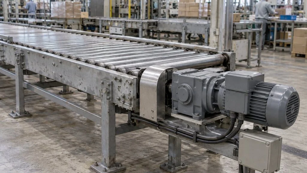
Imagine you are troubleshooting a conveyor or a chain-driven transfer unit built in Japan. In the control panel, next to the motor's magnetic contactor and thermal overload relay, there is a small DIN-rail unit with three dials labeled CURRENT, START TIME, and SHOCK TIME. The electrical drawing calls it ショックリレー (shokku rire, "shock relay"). The line keeps stopping, the unit's overcurrent lamp is lit, and the first instinct on the floor is to turn the CURRENT dial up.
A shock relay is a current-monitoring relay designed mainly to protect the driven machine. It watches motor current, and when the current stays above a set level for longer than a set time, it switches an output contact that stops the motor through the control circuit. Its job is to catch a jam before chains, gear reducers, and other drive parts are damaged. A thermal overload relay, by contrast, protects the motor windings from overheating. The two devices do different jobs, and one does not replace the other.
This guide explains what a shock relay is, what the same function is called outside Japan, how it differs from a thermal overload relay, what its three settings do, and what to check when it trips. It ends with a checklist and a list of questions to send to the Japanese equipment supplier.
Contents
What Is a Shock Relay?
Figure 1: Detecting a Conveyor Jam from Motor Current
The relay turns a mechanical problem into an electrical signal and tells the contactor to stop the motor.
Conceptual diagram for a direct-on-line (DOL) motor. Actual terminals and stop circuits follow the relay model and the machine's design. On a phone, scroll the figure sideways.
When something gets caught in a conveyor, the motor keeps trying to turn and works harder against the obstruction. Its current rises. The shock relay catches that rise and gives early warning of an overload on the chain, gear reducer, or other drive parts.
A current-monitoring shock relay does not measure shaft torque directly. It infers load from the change in motor current. To set one, you need two things: the current the motor draws in normal operation, and the load limit of the machine you want to protect.
The same idea works on crushers and mixers, where foreign material can suddenly raise the load. What counts as "abnormal" depends on what the driven machine can tolerate, not only on the motor's rating. The way current changes also depends on the application and the speed control, so before you touch any setting, identify the motor type and drive method (direct-on-line or inverter) and document the load conditions of the target machine.
Cutting power does not stop a machine instantly; it may keep moving on its own inertia. Tsubakimoto Chain (Tsubaki), the Japanese maker of the Shock Relay product line, warns that its relays may fail to protect equipment with large inertia or a large speed-reduction ratio, and asks users to test before applying one.
On people movers and lifting equipment, measures against injury and falling loads must be built into the machine itself. Do not rely on a shock relay for personnel safety. Treat machine protection and safety functions as separate design items.
What It Is Called Outside Japan
"Shock Relay" (ショックリレー) is Tsubaki's product name (shown with the registered trademark symbol on Tsubaki's Japanese site). Other makers sell similar functions under different names, so when you look for a local replacement or a comparable device, search for the function instead.
Table 1: Names You May Meet for the Same Kind of Protection
These terms overlap but are not interchangeable. Check what each specific product actually detects.
| Term | What it usually means | Note |
|---|---|---|
| Shock relay (Tsubaki) | Current-monitoring relay that trips when current stays above a setting for a set time, with a start-up delay | Tsubaki also sells it outside Japan under this name, listed as "electronic shock relays" for overload protection |
| Current monitoring relay / current sensing relay | Relay that compares measured current with a threshold and switches a control output | Overcurrent types can detect a jammed conveyor; undercurrent types can detect a broken belt or lost load |
| Load monitor relay | Common shop-floor name for the same mechanical-protection use | Some products monitor motor power instead of current |
| Electronic overload relay (with jam protection) | Motor overload relay that measures current electronically; some models add jam or stall detection | Jam detection is an option on some models, not standard on all |
| EOCR (electronic over-current relay) | Product line seen in Asian markets, sold under the Schneider Electric brand | Listed functions include overcurrent, phase loss, and locked rotor with start-up and trip delays |
| Mechanical overload protection (torque limiter) | A mechanical device in the drive train that slips or disconnects at a set torque | Tsubaki classifies torque limiters as mechanical overload protection, separate from its electrical relays |
Product names and functions are taken from manufacturer and distributor pages listed under Sources. Confirm the detection method and settings on the datasheet of the actual model.
Tsubaki also makes a related device called the Shock Monitor. It monitors motor input power rather than current, and Tsubaki describes it as a power-monitoring device that can catch smaller load changes. If a Japanese drawing shows ショックモニタ (shokku monita), it is not the same device as a shock relay.
Shock Relay vs. Thermal Overload Relay
Figure 2: Same Overcurrent, Different Things Protected
Machine overload, motor heating, and short circuits each have their own protective device.
| Item | Shock relay | Thermal overload relay | Circuit breaker / fuse |
|---|---|---|---|
| Main purpose | Limit machine damage from jams and similar faults | Prevent motor burnout from overload | Protect the circuit from short circuits and similar faults |
| Detection and action | Judges current level and how long it lasts | Current heats a bimetal strip, which bends | Detects and interrupts overcurrent / fuse element melts |
| Timing | Adjustable start-up delay and overload delay | Inverse-time: the higher the current, the faster it trips | Selected for short-circuit current and protection coordination |
| How it stops the motor | Output contact into the stop circuit | Auxiliary contact to the contactor coil | Opens the main circuit itself |
The thermal column describes a typical bimetal (thermal) type. Features such as phase-loss protection vary by model. On a phone, scroll the table sideways.
A shock relay suits machines whose load can jump suddenly: it stops them after a delay you set. A thermal overload relay (サーマルリレー, samaru rire, on Japanese drawings) protects the motor windings from the heat of a sustained overcurrent.
In a typical thermal overload relay, motor current flows through a heater that warms a bimetal strip. The strip bends as it heats and trips a contact. It models motor heating indirectly; it does not measure winding temperature. Its trip time depends on how large the overcurrent is and how warm the relay already is, so the same current trips a hot relay sooner than a cold one. Under IEC 60947-4-1, an overload relay's trip class (Class 10, 20, 30) gives the maximum trip time in seconds at 7.2 times the current setting.
With a shock relay, you set the time it waits through normal, short load changes to suit the machine. If you need to stop the machine before it is damaged, check separately whether you can afford to wait for the thermal relay to trip.
That is also why adding a shock relay is no reason to remove the motor's thermal protection. Short-circuit interruption is a third, separate job. Combine the devices that signal a stop through contacts with the fuses and circuit breakers that protect the circuit, so no fault type is left uncovered.
Related: Circuit Protector (CP) vs. Circuit Breaker (NFB) and Fuse
Related: Thermal Trip: Why Thermal Relays Trip and How to Reset
How a Shock Relay Works
Figure 3: A CT Picks Up the Current Without Cutting the Wire
The motor power wire passes through a magnetic core; a winding on the core produces a signal proportional to the current.
Principle of a single CT. On Tsubaki's SB series, two of the motor's three phase wires each pass through their own CT, in the same direction. The figure does not show all phases going through one hole.
A CT (current transformer, 変流器 henryuki) is a sensor for measuring current. Passing the motor power wire through the CT gives the relay a signal it can evaluate, without breaking into the main circuit.
When the machine load rises and the current exceeds the current setting, the relay starts timing the shock time. If the excess lasts for the set time, the output contact changes state and signals the fault to an external stop or alarm circuit.
The relay's output contact and the contactor's main contacts do different jobs. The output contact only signals. In a direct-on-line starter, the usual arrangement wires the output into the magnetic contactor's control circuit, and the contactor's main contacts open to cut motor power. Treat the output as a dry contact that opens or closes a circuit, not as a power source, and match it to the voltage and current of the circuit it switches.
Related: Dry Contact vs Wet Contact: Reading Japanese Specs
Some machines also bring the fault into a PLC (programmable logic controller). Check the contact's minimum allowable load first. For the SB series, the manual says to pass the signal through a relay rated for small currents rather than wiring the output contact straight into the PLC input, because of the risk of contact failure at very low current. From the PLC side, the fault is a digital input. When you read the circuit diagram, follow two paths separately: the one that shows the fault on the HMI and the one that actually stops the machine.
Related: DI/DO, AI/AO, PI/PO Meaning: Reading a Japanese I/O List
When a motor starts, it draws a large inrush current, which is normal. If the relay judged start-up the same way as running, it would trip every time. That is what the start time is for: the relay waits until the start-up transient settles before it watches for overload.
CT wiring matters too. The number of times the wire passes through the CT and its direction must match the model's instructions. The same motor current gives a different signal depending on the number of turns, so keep the relay setting and the CT wiring documented together.
The Three Settings: Current, Start Time, and Shock Time
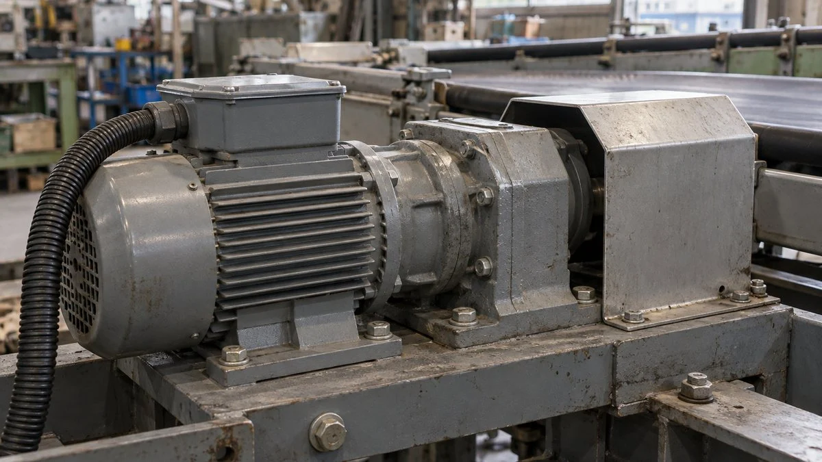
Setting a shock relay starts with finding out how the healthy machine draws current. Record start-up and steady running separately, and include the range of loads and materials the machine normally handles. Only then can you tell where normal ends and abnormal begins.
At the same time, find out how much force the machine can take and how quickly it must stop. A setting that passes normal operation but lets the machine be damaged during a fault is not protection. The final values have to satisfy both sides.
Write down the operating speed, the amount of product on the conveyor, and the starting method next to each current reading. A current value alone will not tell you later whether the load increased or the operating conditions changed.
Figure 4: Separating Inrush, Short Peaks, and Sustained Overload
After the start time ends, the relay compares how long any excess lasts with the shock time.
Conceptual waveform to explain the logic, not measured data. In this example the contactor opens after the output and the current drops to zero. The machine may still coast on its inertia after the current is gone.
Current Setting
The current setting is the line between normal and overload. Do not base it on no-load current alone. Measure the range of current, including the heaviest condition the machine sees in normal operation.
On a conveyor, for example, an empty belt and a loaded belt need different driving force. Record not just the usual load but the maximum load you accept as normal.
The target is a value that passes the highest normal current but trips before the machine's load limit is exceeded. A record that links load to current is a better basis than a fixed multiple of the motor's rated current.
Set it too low and the relay trips in normal operation; set it too high and it misses the faults you want to catch. If the difference between normal and fault current is small, adjusting the threshold may not separate them reliably.
In that case, review the protection method with the equipment maker, including ways to detect the fault on the machine side. Current monitoring and power monitoring are separate methods, which is why Tsubaki lists its Shock Monitor as a power-monitoring device.
Start Time
The start time is a start-up delay that keeps inrush current from causing a false trip. Measure how long the current takes to settle to its normal level after start, and set a delay that rides through that transient.
An empty conveyor may come up to speed quickly, while starting with product on the belt can make acceleration take longer. Test under the starting conditions the machine really uses, and confirm the relay does not trip on every normal start.
The longer the start time, the longer it takes to detect a fault that happens during start-up. According to the SB series manual, if an overload occurs during start-up, the relay trips only after the start time plus the shock time has passed.
With an inverter (VFD), acceleration, deceleration, and output frequency change how the current behaves. The supported frequency range differs by model, so confirm the relay model and where the CT is installed against that model's manual.
Shock Time
The shock time is how long the current may stay above the setting before the relay calls it a fault. It lets through short peaks that also occur in normal operation, such as when product transfers from one conveyor to another.
Too short, and normal momentary loads stop the line. Too long, and damage progresses during a jam. Measure both how high the current peaks go and how long they last, then compare that with how long the machine can tolerate an overload.
As one example, the SB series offers a shock time range of 0.2–5 s. That is the product's adjustable range, not a recommended stopping time for any machine and not a value that applies to all models.
When you think about where the machine will actually stop, include the contactor's operating time after the output and the machine's coasting. For illustration only, assume 0.4 s from the fault to the relay output and 0.6 s from the output to a full stop.
The calculation shows that the shock time alone does not decide where the machine stops. On the real machine, test the stop, measure the time from detection to standstill and the distance traveled in that time, and judge from those numbers.
Figure 5: Records to Check Before Changing Any of the Three Settings
An adjustment that reduces nuisance trips is also an adjustment that delays protection.
| Setting | Base it on | If set too low / short | If set too high / long |
|---|---|---|---|
| Current setting | Maximum normal load and the machine's load limit | Trips in normal operation | Misses overloads |
| Start time | Time for current to settle under real starting conditions | Trips right after start | Slow to detect faults during start-up |
| Shock time | Duration of normal peaks and the time the machine can tolerate a fault | Trips on momentary loads | Cannot stop the machine before damage |
After changing any value, test both that normal operation runs without trips and that the expected fault is detected, using a safe method.
Manufacturers' manuals give their own adjustment sequence. The SB series manual, for example, has you set the start time first, then the current, then the shock time, starting from specified initial positions. Follow the manual for the exact model in your panel rather than a generic procedure, including this one. Note that the dial scales are not the full adjustable range on every model; the SB manual says to check timing with the TEST button for settings beyond the scale.
When It Trips: What to Check
After a trip, first record when the machine stopped and whether it was right after start or during running. If you raise the settings first, you risk dismissing a real jam or rising mechanical resistance as a nuisance trip.
- Record the process step where the machine stopped, the load at the time, any lamps or alarms, and the current settings.
- Isolate power and secure moving parts, then look for foreign objects and problems in the drive train.
- Remove the cause, then compare with the normal-operation records to decide whether a setting change is really needed.
- Confirm the restart conditions, make the area safe, and run an operational test.
Wiring and inspection should be done by qualified people, following the manual for the specific model. Work inside a machine requires more than isolating power: also prevent movement from falling parts or stored energy, following your site's lockout/tagout procedures.
If the relay output has changed but the machine did not stop, trace the stop circuit beyond the relay. On a PLC-controlled machine, compare the input state with the run-permit signal to find where the path breaks. One way to check a contact is a continuity test with the circuit de-energized; do not measure resistance on a live circuit.
Related: How to Measure Current with a Multimeter (Japanese Testers)
Related: How to Read Japanese PLC Programs: Mitsubishi X/Y/M/D
After recovery, record the settings before and after the change and the test results against the equipment number. Add the operational check and the record update to the maintenance plan so that you can compare again whenever the load conditions change.
Related: TBM vs CBM: Time-Based vs Condition-Based Maintenance
A test using the relay's built-in test function and a test of the full stop path cover different things. Do not stop at seeing a lamp change; check that the circuit receiving the output ends up in the designed state.
Test methods are specified per model. On the SB series, for example, the TEST button is meant to be used with the motor stopped. Do not deliberately jam the real machine to test the protection; use the method the manufacturer specifies to reproduce the condition safely.
Checklist and Questions for the Japanese Supplier
Use this list when a Japanese machine with a shock relay arrives, when you plan a replacement, or before anyone changes a setting.
On-Site Checklist
- Relay maker and full model number, from the nameplate and the parts list
- Current, start time, and shock time settings as found (photograph the dials)
- CT type, which phases pass through it, number of turns, and direction
- Output mode: self-holding (on the SB series, reset with the RESET button) or automatic reset
- Where the output goes: contactor coil circuit, PLC input (through an interposing relay?), alarm
- Control supply voltage of the relay
- Drive method: direct-on-line or inverter, and the inverter frequency range in use
- Thermal overload relay and short-circuit protection still present and correctly set
- Normal-operation current records: start-up, empty, maximum normal load
- A record of the stop test: time and distance from detection to standstill
Questions to Ask the Japanese Side
- What machine fault is the shock relay meant to detect (jam, chain overload, gearbox protection)?
- How were the current, start time, and shock time values decided? Do you have the measured current data?
- What is the allowable load or torque of the protected parts, and how fast must the machine stop?
- Is the relay output self-holding or automatic reset? After reset, can the machine restart on its own?
- Is the relay approved for inverter drive at our operating frequency range?
- If we replace it with a locally available current monitoring relay or electronic overload relay, which functions and settings must it have?
- Are there personnel-safety or fall-prevention functions on this machine that do not depend on the shock relay?
A short inquiry you can adapt:
Subject: Shock relay settings for [machine name / serial no.]
We are maintaining the [conveyor] you supplied. The shock relay [maker, model] in the control panel is set to current [__ A], start time [__ s], and shock time [__ s], and it has tripped [__ times] since [date]. Please tell us how these values were determined, the measured normal current, and the load limit of the protected parts. Please also confirm whether the output is self-holding or automatic reset, and which functions a substitute relay would need if we replace it locally.
Limits of This Guide
- Specific ranges and behavior cited here come from Tsubaki's SB and ED series documents. Other models and other makers' products differ.
- This guide explains principles and what to check. It is not a setting procedure. Settings must follow the manual of the installed model and the judgment of the machine's designer.
- A shock relay is machine protection. Whether a machine is safe for people is a separate question for the machine's safety design and local regulations.
- The calculation example uses fictional values. Real stopping time and distance must be measured on the machine.
- Names in Table 1 overlap. Whether a local product can replace a shock relay depends on its detection method, timing ranges, and output, and should be confirmed with the supplier.
FAQ
What Does a Shock Relay Detect?
A current-monitoring shock relay detects motor current above the setting and how long it stays there. It infers the machine's load from current, so it is different from a sensor that measures shaft torque directly.
Can a Shock Relay Replace a Thermal Overload Relay?
No. The shock relay protects the driven machine from jams; the thermal overload relay protects the motor from overheating. Installing a shock relay is not a reason to remove the motor's thermal protection, and short-circuit protection from fuses or circuit breakers is a separate job again.
Should the Shock Time Be Set as Short as Possible?
Not as a goal in itself, because normal momentary peaks can then stop the machine. Compare the duration of normal peaks with the time the machine can tolerate a fault, and include the stopping delay after detection.
With Automatic Reset, Does the Machine Restart by Itself?
The relay contact returning to normal and the machine restarting are separate events. In a circuit where the run command stays on, an automatic reset can lead to a restart, so check the reset mode and the run-permit conditions together. A fault signal that stays latched behaves differently from a signal that appears only while a button is pressed.
Related: Pulse vs Status Signals: Momentary vs Maintained Commands
Can a Shock Relay Be Used with an Inverter-Driven Motor?
Yes, if the model and its frequency range match, but the conditions differ across Tsubaki's series. The ED series lists 20–200 Hz for inverter drive. The SB series manual warns that current waveform distortion under an inverter can cause malfunction and says it can be used at 30–60 Hz, where the effect is minor. Do not apply one model's range to another.
Sources
- Shock relay and shock monitor definitions; electrical vs. mechanical overload protection: Tsubakimoto Chain, electrical control devices product information (Japanese)
- Detection, wiring, settings, test button, and maintenance: Tsubakimoto Chain, Shock Relay SB Series instruction manual (Japanese, February 21, 2024); U.S. Tsubaki, TSBSB Shock Relay instruction manual (English)
- Reset modes and application cautions (inertia, people movers and lifting): Tsubakimoto Chain, notes on using shock relays (Japanese)
- Inverter-compatible model example: Tsubakimoto Chain, Shock Relay ED Series (Japanese)
- Tsubaki shock relays sold outside Japan: Tsubaki of Canada, Electronic Shock Relays
- Thermal overload relay construction, trip timing, and short-circuit protection: OMRON, technical guide to low-voltage switchgear (Japanese)
- Trip class under IEC 60947-4-1: ABB, thermal overload relays technical data
- Current monitoring relays (overcurrent and undercurrent uses, output does not interrupt load current): VIOX, "Current Monitoring Relay Explained"
- Jam detection on electronic overload relays: Rockwell Automation, "New Electronic Overload Relay Helps Prevent Motor Damage, Downtime" (Allen-Bradley E100)
- EOCR product line (functions listed): Bao An, Schneider EOCRSS listing
Original article in JapaneseThis guide is adapted from a MONOSCOPE article written for readers in Japan: ショックリレーとは?電流監視の原理とサーマルとの違い・設定方法
About the editor
 MONOSCOPE EditorFOUNDER & EDITOR
Spent about ten years at a plant equipment maker and a plant engineering company, proposing, designing, and commissioning equipment, then moved into web marketing. Now a web consultant for B2B manufacturers, helping them explain their products and technology. Licensed in Japan as an Energy Manager and a Third-Class Chief Electrical Engineer.
Has run an engineering blog since 2017 (500+ articles) and a Japanese YouTube channel with about 20,000 subscribers. Each English guide is written from the Japanese shop-floor point of view and checked against the cited standards.