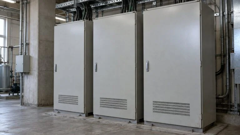
Japanese Machine Control Panels: UL 508A, NFPA 79, and CE
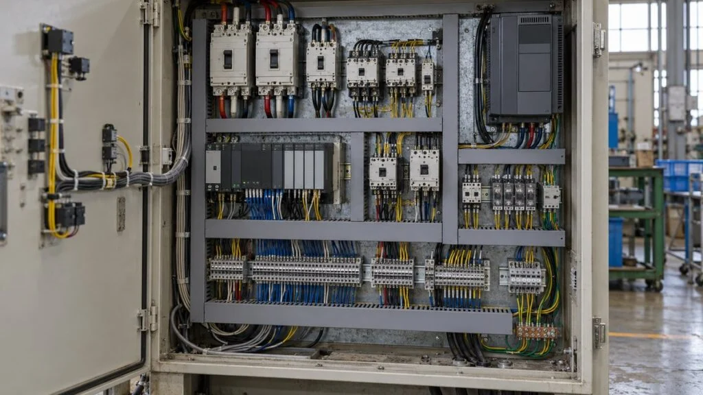
Say your plant in Ohio orders a machine from a Japanese builder. It arrives with a control panel full of Japanese breakers, wired for 200 V, with a nameplate that shows voltage and full-load current but no short-circuit current rating (SCCR). The local electrical inspector will not sign off, and your maintenance team now has to decide whether to rework the panel, replace it, or send it back.
Most of these problems trace back to two decisions the Japanese side makes before drawing a single circuit: what the panel must connect to, and which standards it must meet. If the buyer does not state the destination, the supply voltage, the available fault current, and the target standards (UL 508A, NFPA 79, and the NEC for the US; CE marking and IEC/EN 60204-1 for Europe) in writing at the start, the supplier has to guess, and the default is often Japanese domestic practice.
This guide walks through how a control panel is typically designed in Japan, points out where your input changes the design, and ends with a question list and a sample inquiry you can send to the supplier. It is written for buyers, project engineers, and maintenance engineers, not as a design manual.
Contents
- How Japanese Builders Design a Control Panel: 7 Steps
- Steps 1 and 2: Specs and Standards the Buyer Must Supply
- Exporting to the US: UL 508A, NFPA 79, and the NEC
- Exporting to Europe: CE Marking and the Machinery Regulation
- Steps 3 to 5: Design Details Worth Asking About
- Steps 6 and 7: Drawings, Nameplate, and Pre-Shipment Inspection
- Common Problems and How Buyers Prevent Them
- Checklist: Questions to Send the Japanese Supplier
- Limits of This Guide
- FAQ
- Sources
How Japanese Builders Design a Control Panel: 7 Steps
A control panel is an enclosure that holds the equipment feeding and controlling loads such as motors and heaters: circuit breakers, contactors, a PLC (programmable logic controller), inverters (VFDs), and terminal blocks, all wired to a defined circuit. Company names for each stage differ, but the work usually breaks down into the seven steps in Figure 1.
Decide, design, then verify. Your input matters most in Steps 1 and 2.
Steps 3 to 5 loop back and forth: a different inverter changes the heat load, which can change the enclosure size or cooling method.
Changes within Steps 3 to 5 mean rework among the circuits, layout, enclosure size, and cooling. A change in Step 1 or 2 reaches the whole design. If the destination switches from Japan to North America after design starts, the usable breakers change, the nameplate changes, and the drawings change with them. That is why the first two steps, where the buyer's information goes in, deserve the most time.
Steps 1 and 2: Specs and Standards the Buyer Must Supply
These two steps produce no drawings, but they decide everything from component selection to the inspection items. Japanese builders typically ask for the following, and they expect the answers in writing rather than in a phone call:
- Power supply: voltage, number of phases, frequency, and grounding (earthing) system. Japanese factory practice is often 200 V class at 50 or 60 Hz, so a US 480 V or 208 V supply must be stated clearly (see Japan industrial voltage: 200 V 3-phase and 50/60 Hz).
- Loads: motor ratings and quantities, starting methods, and a list of heaters, valves, and other loads.
- Site conditions: ambient temperature, dust and water exposure, indoor or outdoor.
- Operation and indication: push buttons, touch panel, pilot lights, and the location of emergency stops.
- Destination: country of installation, plus any standards or in-house specifications the buyer requires.
- Available fault current: the short-circuit current the plant supply can deliver at the panel's incoming terminals.
You do not have to invent a format. IEC 60204-1 (published in Japan as JIS B 9960-1) includes an informative Annex B, an enquiry form the user and supplier can use to exchange these conditions. The standard says machine builders can also use it as a checklist, so it works well as the basis of your specification sheet. For broader purchase specs, see equipment purchase specifications.
Which Standards Apply Depends on Where the Panel Goes
For control panels on industrial machinery, the Japanese baseline is JIS B 9960-1:2019, "Safety of machinery – Electrical equipment of machines – Part 1: General requirements." It is identical in content to IEC 60204-1:2016, and an amendment (Amendment 1) was issued in 2023. It covers machine electrical equipment with a nominal supply voltage up to 1,000 V AC or 1,500 V DC and a nominal frequency up to 200 Hz, and it addresses supply disconnection, protection against electric shock, overcurrent protection, control circuits, wiring, marking, technical documentation, and verification.
Japanese drawings and specs also cite JEM standards from the Japan Electrical Manufacturers' Association (JEMA): JEM 1122 for wiring and wire types inside panels, JEM 1323 for grounding, JEM 1459 for construction and dimensions, and JEM 1460 for ratings and tests. The Japan Switchboard & Control System Industries Association (JSIA) also publishes industry standards, such as those for cabinet-type power control panels. Do not confuse these with JIS C 8480:2023, which covers cabinet-type distribution boards for buildings; it is not a product standard for machine control panels and serves only as a reference for enclosure construction. All of these are domestic standards. Seeing them on a drawing tells you the panel was designed to Japanese practice, not that it meets UL or EN requirements.
Where the panel will be installed decides which set of standards applies.
Which standards actually apply is set by the buyer's specification and the laws at the installation site. If in doubt, confirm in writing before design starts.
One point catches buyers out. In Japan, molded case circuit breakers and earth leakage breakers rated 100–300 V AC and up to 100 A (for motor use, motors up to 12 kW; special designs built into machinery are excluded) fall under the Electrical Appliances and Materials Safety Act and must carry the PSE mark. That mark shows compliance with Japanese law only. It is not a UL listing and does not satisfy US requirements. For how Japanese breaker names map to MCCB and RCD, see NFB vs. MCCB vs. ELB.
Exporting to the US: UL 508A, NFPA 79, and the NEC
The basic step sequence stays the same for export. What changes is the standard chosen in Step 2 and, with it, component selection, markings, and how compliance is shown.
In the US, electrical installations follow the National Electrical Code (NEC, NFPA 70). States adopt the NEC into law, and each state chooses which edition to adopt. The NEC is revised every three years; as of October 2026, NFPA lists the 2026 edition as current. NEC Article 409 covers industrial control panels and defines them as assemblies of two or more power-circuit or control-circuit components, which covers most of what people call a control panel. (The article numbers below come from the NEC 2017 and NFPA 79 2018 text quoted in Fuji Electric's SCCR guide. Check the edition adopted at your site.)
UL 508A is the product standard for industrial control panels. Manufacturers enrolled in the UL Solutions Panel Shop Program can apply the UL Mark to panels built to UL 508A without a separate evaluation for each design. The program covers certification for both the US and Canada. UL 508A's third edition was published in April 2018 and has been revised since; as of October 2026, the UL Standards & Engagement store lists June 26, 2025 as the latest revision date.
NFPA 79 covers the electrical equipment of industrial machinery in the US, much as IEC 60204-1 does internationally. NFPA lists the 2024 edition as current, with a 2027 edition planned. For Canada, the industrial control panel standard is CSA C22.2 No. 286, "Industrial control panels and assemblies," currently the 2023 edition.
There is also a workplace-safety side. Under OSHA's electrical rules for general industry (29 CFR 1910.303(a)), electrical equipment is acceptable only if it is "approved," which 1910.399 ties to listing, labeling, or certification by a Nationally Recognized Testing Laboratory (NRTL). UL is one NRTL. This is a major reason US plants and inspectors ask for listed panels and listed components.
SCCR: Where Most US Rework Happens
The item most likely to send a Japanese panel back for rework is the short-circuit current rating (SCCR): the maximum fault current a panel can withstand. NEC 2017 Section 409.110 requires the SCCR to be marked on the panel, and NFPA 79 (2018), Section 4.9, says the available fault current at each machine supply disconnect must not exceed the SCCR on the panel nameplate. The NEC cites UL 508A Supplement SB as one approved method for determining the rating.
Find each component's rating; the lowest value becomes the panel's rating.
Summary based on Mitsubishi Electric and Fuji Electric technical documents. Default values and adjustment conditions can change with UL 508A revisions. Actual ratings follow the current UL 508A text and each component's certification conditions.
Marking the SCCR is the machine builder's job, but in practice the buyer specifies the value needed. A requirement of 5 kA is usually easy with ordinary components. A requirement of 50 kA can force the builder to rethink component selection from the start. Builders typically reach higher ratings with tested breaker-and-starter combinations. Mitsubishi Electric, for example, publishes a case in which a contactor and thermal overload relay rated 5 kA on their own reach 25 kA at 240 V AC when paired with a specified UL 489 breaker. Such combination ratings hold only under the maker's published conditions (breaker type, voltage, rating) and vary by model.
What to do as the buyer: have your electrical engineer or utility determine the available fault current at the point where the machine will connect, and put the required SCCR in the purchase specification. The fault current depends on your plant's supply, so it has to come from your side.
Other US Items to Raise With the Supplier
Beyond SCCR, a panel designed to IEC or Japanese practice can differ from US expectations in component listings, wire sizes (mm² vs. AWG), wire types and colors, and nameplate content. Rather than assume either way, ask the supplier which standard each of these was designed to and whether the components carry UL listing or recognition for the way they are used. A circuit protector (CP) is a common example: many are supplementary protectors in North America and cannot serve as branch-circuit protection (see circuit protector vs. circuit breaker).
Exporting to Europe: CE Marking and the Machinery Regulation
In the EU, the manufacturer confirms that the product meets the applicable legal requirements, prepares the technical file and an EU declaration of conformity, and then applies the CE marking. Some product types also require a third-party notified body.
The main laws are the Machinery Directive 2006/42/EC, the Low Voltage Directive 2014/35/EU (electrical equipment for use at 50–1,000 V AC and 75–1,500 V DC), and the EMC Directive 2014/30/EU (electromagnetic emissions and immunity). Which laws a declaration rests on can depend on how the panel ships, for example as a standalone panel or as part of a machine. Confirm this for each project with a notified body or a compliance specialist.
The Machinery Directive is being replaced by the Machinery Regulation (EU) 2023/1230. According to the European Commission, machinery placed on the market before January 20, 2027 follows the Directive, and the Regulation applies from that date. If delivery could slip into 2027, agree early on which one the supplier will demonstrate conformity to.
Technical requirements are usually met through harmonized standards: EN 60204-1 for machine electrical equipment and the EN IEC 61439 series for the assembly. The list of harmonized standards is published in the Official Journal of the EU, so check the edition listed at the time.
The legal basis and the way compliance is shown differ.
A comparison of typical items. Other laws and standards can apply depending on the product and destination.
Steps 3 to 5: Design Details Worth Asking About
You do not need to check the supplier's circuit design, but knowing what IEC 60204-1 expects helps you read the drawings and ask sharper questions. Each item below has scope limits and exceptions in the standard itself.
Circuits and Drawings
Panel circuits are split into power circuits, which feed the loads, and control circuits, which switch them on and off. A typical layout runs from a main disconnect or main breaker to branch circuits: breaker, contactor, and thermal overload relay for a motor; breaker and inverter for a VFD; and a transformer or DC power supply for the PLC and relays.
Japanese designers usually start with a single-line diagram, then develop schematics (often called sequence diagrams) using JIS C 0617 symbols, the Japanese version of the IEC 60617 graphical symbols. Part 7, which covers switchgear, controlgear, and protective devices, was last revised in December 2024 as JIS C 0617-7:2024. Panel drawings may also follow JEM 1404 for schematic format and JEM 1115 for terms and letter symbols. For reading interlocks and wiring designations on these drawings, see interlock circuit diagrams and naisen vs. gaisen (panel vs. field wiring).
Examples of what IEC 60204-1 (JIS B 9960-1) asks for, which you can look for on the drawings and the finished panel:
- Supply disconnect (5.3.4): operating handle outside the enclosure, between 0.6 m and 1.9 m (about 2 ft and 6.2 ft) above the servicing level, with 1.7 m (about 5.6 ft) recommended as the upper limit. Power-operated switches have exceptions.
- Control circuit supply (9.1.1): when fed from AC, control circuits are supplied through a transformer with separate windings, with exceptions such as small machines with a single motor starter.
- Control voltage (9.1.2): nominal values should not exceed 230 V at 50 Hz, 277 V at 60 Hz, or 220 V DC. This is a recommended ceiling; the actual voltage comes from the buyer's spec and the destination's standards.
- Stop functions (9.2.2): stop category 0 (immediate removal of power), 1 (controlled stop, then power removed), and 2 (controlled stop with power maintained). Emergency stops act as category 0 or 1, chosen from the risk assessment.
- Actuator colors (10.2): emergency stop red on a yellow background; start buttons white, gray, black, or green (white preferred), never red.
Emergency stops, guard interlocks, and other safety circuits get their required performance from the machine's risk assessment, and the underlying approach comes from functional safety and the IEC 61508 framework. This article does not cover their design. Ask the supplier which safety standards they applied, and have a qualified safety engineer review them.
Protection: Overload and Short Circuit Are Handled Separately
Japanese designers split motor circuit protection into two roles. In Fuji Electric's selection guide, the magnetic starter with a thermal overload relay handles motor overload, while the molded case circuit breaker or earth leakage breaker handles short-circuit protection. The contactor is applied at utilization category AC-3 (starting squirrel-cage motors and switching them off while running).
Breakers are usually sized well above motor current so that starting current does not trip them. In Fuji's table, a 200 V, 3.7 kW (about 5 hp) motor has a rated current of 15.5 A and a starting current of 139 A, and the matching breaker is rated 40 A. The motor values are Fuji catalog figures for totally enclosed fan-cooled, 4-pole, 50 Hz, premium-efficiency (IE3) motors. The table assumes direct-on-line starting, a starting time of 6 seconds or less, breakers chosen with 1.3 times the starting current as the maximum starting current, and Fuji devices throughout, and it notes that long-starting loads need a different breaker or overload relay. Treat it as an illustration of the logic, not as values to reuse. Different motor or device makers give different currents and combinations, so these numbers do not transfer to another design. For how overload relays behave in service, see thermal overload relays.
Wire sizes are set by two checks: whether the wire's ampacity covers the current, and whether the upstream protective device can protect that wire. IEC 60204-1 Table 6 gives example ampacities for PVC-insulated copper wire at 40°C (104°F), for example 13.5 A for 1.5 mm², 18.3 A for 2.5 mm², and 24 A for 4 mm² in conduit or ducts (method B1), for one loaded three-phase circuit. Those values alone do not set wire size: they are corrected by Annex D factors for grouping and temperature, and the standard limits voltage drop on power circuits to 5% of nominal. Domestic Japanese panels may also follow JEM 1122 for wire types and color coding. If the panel goes to the US, ask how wire sizes and types were checked against US requirements.
Layout, Noise, and Heat
Layout has to balance heat, electrical noise, and maintenance access. Typical practice is to leave space above and below heat sources such as inverters and power supplies, run power and signal wiring in separate ducts with short parallel runs, keep protective bonding (for shock protection) and functional bonding (for noise control) as separate plans, and leave room to operate breakers, retighten terminals, and replace parts. IEC 60204-1 gives guidance on reducing electromagnetic effects in its informative Annex H, and device manuals add their own wiring and grounding instructions. Japanese designers follow the device maker's instructions first and use the annex to fill gaps. For field cable shields, see cable shield grounding.
Heat deserves a direct question. Rittal notes that the inside of a panel tends to run about 10–20°C (18–36°F) above ambient, and a common rule of thumb says a 10°C rise halves the expected life of an electrolytic capacitor. The cooler maker Apiste recommends designing for a 35°C (95°F) internal temperature. A panel sized in Japan for a mild indoor plant may need fans, a heat exchanger, or an enclosure air conditioner in a hot US or Southeast Asian facility. IEC/TR 60890 describes a calculation method for temperature rise in assemblies.
Enclosure Protection (IP Code)
The IP code's first digit rates protection against solid objects and the second against water. IEC 60204-1 Section 11.3 requires enclosures for controlgear to provide at least IP22, with exceptions. That is a floor, not a target: dusty or wet locations need more, and higher sealing also traps more heat, so IP rating and cooling should be decided together. In the US, enclosures are also commonly specified by NEMA type, so state which rating system your spec uses.
On older Japanese documents you may see the IP standard cited as JIS C 0920. That standard was withdrawn on January 20, 2026 and replaced the same day by JIS C 60529:2026, which now matches the IEC 60529 number and adds IPX9 (high-pressure, high-temperature water jets). JIS B 9960-1:2019 itself still cites the old number. Read "JIS C 0920" as the current JIS C 60529.
Steps 6 and 7: Drawings, Nameplate, and Pre-Shipment Inspection
The drawing set normally includes schematics, an enclosure outline, an internal component layout, terminal arrangements, and a parts list. JEM 1268 lists the types of drawings and specifications exchanged between buyer and manufacturer. Drawings submitted for your approval are often stamped as approval drawings; see approval drawings (shonin-zu).
The nameplate shows the supplier name, voltage, phases, frequency, and full-load current. JIS B 9960-1 also requires the short-circuit current rating for each incoming supply as installation information. The 2019 revision added Section 7.10, which requires the short-circuit current rating of the electrical equipment to be determined by applying design rules, by calculation, or by testing. It is the same idea as SCCR in North America.
Without a machine-specific product standard, four items are always required; the others apply as needed.
Test voltages and pass criteria are set in the standard. A machine-specific product standard, where one exists, takes precedence.
For domestic panels, JEM 1460 sets ratings and tests and splits them into factory and site tests; it was revised in March 2026. If the supplier's inspection procedure cites JEM 1460, ask which edition. Energized testing and commissioning carry shock and unexpected-start hazards. Work with the power off should follow lockout/tagout, and work near live parts should follow your site's safety rules and be done by trained people. For planning the factory and site acceptance tests, see FAT and SAT with Japanese suppliers.
Common Problems and How Buyers Prevent Them
Destination or Supply Voltage Confirmed Too Late
"It's actually going to the US" or "the site voltage is different" comes out after design has started. Breakers, wire, and the nameplate all change, so this causes the widest rework. Prevent it by exchanging the destination, applicable standards, supply conditions, and required SCCR in writing at the spec stage. Mark anything undecided as "TBD" with a date for the decision.
Heat Checked Only After the Enclosure Is Fixed
The enclosure size is set, components are packed in, and the temperature problem shows up later. Adding a cooler after the build means cutting the door or side and adding a power circuit. Ask for a rough temperature-rise estimate once the component list exists, before the enclosure size is final, and give the supplier your real maximum ambient temperature.
Components Chosen One at a Time
Picking each breaker and contactor from its catalog rating alone can break protection coordination in domestic panels and leave the SCCR lower than expected in North American ones. Device makers publish combination tables by motor size and lists of SCCR combination ratings. Ask the supplier whether these were used and whether the table conditions match your circuits.
Drawings That Do Not Match the Panel
Changes made during build or commissioning do not make it back into the drawings, so the as-delivered drawings differ from the real panel. Your maintenance team cannot trust them during breakdowns. This is why "check against the technical documentation" is the first verification item. Make "all changes reflected in the drawings before shipment" a condition of acceptance.
Checklist: Questions to Send the Japanese Supplier
| Topic | What to ask or state |
|---|---|
| Destination and standards | Installation country and state. Required standards (for example UL 508A panel with UL Mark, NFPA 79, NEC edition adopted at site; or CE marking with EN 60204-1). Will conformity be shown under the Machinery Directive or the Machinery Regulation? |
| Power supply | Site voltage, phases, frequency, grounding system. Is a transformer included, and on which side of the supply? |
| Short-circuit rating | Required SCCR (from your available fault current). How was the panel SCCR determined (UL 508A Supplement SB, tested combinations)? Is it on the nameplate? |
| Components | Are breakers, contactors, overload relays, power supplies, and inverters UL-listed or recognized for this use? Are any parts PSE-marked only? |
| Wiring | Which standard were wire sizes, types, and colors chosen to? mm² or AWG? |
| Heat and enclosure | Maximum ambient used in the heat calculation. Cooling method. Enclosure rating (IP or NEMA type). |
| Safety circuits | Stop categories for emergency stops. Which safety standards and risk assessment were used? |
| Documents | Drawing list, schematics, layout, terminal list, parts list in English. As-built drawings at shipment. |
| Inspection | Pre-shipment test list (IEC 60204-1 Clause 18 items, JEM 1460 edition if cited). Can you witness the FAT? |
Sample Inquiry Email
Subject: Control panel requirements for [machine name], installation in [state], USA
Dear [name],
Before you start the electrical design, please confirm the following. The control panel will be installed in [state], USA, and must be built to UL 508A with the UL Mark, and to NFPA 79 for the machine. Our site supply is [480] V, 3-phase, 60 Hz, [grounding system]. The available fault current at the connection point is [xx] kA, so the panel SCCR must be at least [xx] kA and marked on the nameplate. Please tell us (1) how the SCCR will be determined, (2) whether all power-circuit components are UL-listed or recognized for this use, (3) the maximum ambient temperature you will design for (our site reaches [xx]°C), and (4) the list of pre-shipment tests and drawings you will provide in English, including as-built drawings. If any item cannot be met, please let us know before the design is fixed.
Best regards,
[Your name]
Limits of This Guide
- This is a buyer's overview, not a design procedure. Clause numbers and requirements change between editions; the editions of standards and laws mentioned were checked as of October 1, 2026.
- Requirements in standards have scope limits and exceptions, and manufacturers' selection data have built-in assumptions. None of the numbers here can be used directly for design.
- Which US code edition applies is decided by the state and the local authority having jurisdiction (AHJ). Which EU laws apply depends on the product and how it ships. Confirm with your inspector, a notified body, or a compliance specialist.
- Safety circuits (emergency stops, interlocks) need review by qualified safety engineers under the applicable safety standards.
- Japanese makers differ in their in-house standards and drawing formats, so use the checklist as a starting point and adjust it per project.
FAQ
What Is the Difference Between UL 508A and NFPA 79?
UL 508A is the product standard for building and certifying industrial control panels. NFPA 79 covers the electrical equipment of the whole industrial machine and plays the role IEC 60204-1 plays internationally. A machine for the US often needs both: a UL 508A panel on a machine whose electrical equipment follows NFPA 79.
Is a Panel Built to IEC 60204-1 Acceptable in the US?
Not automatically. IEC 60204-1 and NFPA 79 cover similar ground, but US sites usually expect NRTL-listed equipment, NEC compliance, and a marked SCCR. Ask your local inspector what evidence they accept, and state the US requirements in the purchase specification.
What SCCR Should I Ask For?
At least the available fault current at the point where the machine connects. NFPA 79 requires that value not to exceed the SCCR on the nameplate. The fault current depends on your plant's supply, so your electrical engineer or utility has to provide it.
Does the PSE Mark on Japanese Breakers Count as UL Approval?
No. PSE shows compliance with Japan's Electrical Appliances and Materials Safety Act. For US use, ask for components that are UL-listed or recognized for the application.
When Does the EU Machinery Regulation Replace the Machinery Directive?
The Machinery Regulation (EU) 2023/1230 applies from January 20, 2027. Machinery placed on the market before that date follows the Machinery Directive 2006/42/EC.
Sources
- JIS B 9960-1:2019 and Amendment 1:2023: Japanese Standards Association, JIS B 9960-1:2019 (Japanese); Amendment 1:2023 (Japanese)
- IEC 60204-1:2016 requirements (disconnect, control circuits, colors, ampacity, documentation, verification): IDEC, "Safety of Electrical Equipment of Machines (IEC 60204-1)," November 2016, via Japan Machinery Federation (Japanese); IDEC, IEC 60204-1:2016 overview (Japanese)
- JIS B 9960-1 2019 revision (short-circuit current rating, scope, Annex H): Japan Machinery Federation, revision highlights, November 2018 (Japanese)
- JEM standards for switchboards and control panels: JEMA, JEM standards list (Japanese); JEMA, JEM 1460 (Japanese)
- IEC 61439-2:2020: IEC Webstore
- IP code standard change: Japanese Standards Association, JIS C 60529:2026 (Japanese); JSA, on the addition of IPX9 (Japanese)
- Electrical graphic symbols Part 7: Japanese Standards Association, JIS C 0617-7:2024 (Japanese)
- Breakers and the Electrical Appliances and Materials Safety Act: METI, list of specified electrical appliances and materials (Japanese); JEMA, PSE marking of low-voltage breakers (Japanese)
- Motor circuit protection and selection assumptions: Fuji Electric FA Components & Systems, motor branch circuit selection (Japanese)
- Panel heat loads and cooling capacity: Apiste, cooler selection basics (Japanese); Rittal Japan, heat management for enclosures (Japanese)
- Industrial control panels and the Panel Shop Program: UL Solutions, "Industrial Control Panels and the Panel Shop Program"; UL Solutions, "UL 508A Third Edition Summary of Requirements"
- UL 508A revision date, NEC and NFPA 79 current editions: UL Standards & Engagement, UL 508A; NFPA 70 Standard Development; NFPA 79 Standard Development; Intertek, 2025 UL 508A revisions
- NEC Article 409, NFPA 79 and SCCR: Fuji Electric FA Components & Systems, SCCR guide quoting NEC 2017 and NFPA 79 2018 (Japanese); Mersen, "Achieving Higher Short Circuit Current Ratings for Industrial Control Panels"
- SCCR determination and combination ratings: Mitsubishi Electric, UL-certified SCCR combinations (Japanese)
- OSHA approval of electrical equipment: OSHA, 29 CFR 1910.303
- Canadian standard: CSA Group, CSA C22.2 No. 286:23
- Machinery Directive and Machinery Regulation dates: European Commission, Machinery
- Low Voltage Directive voltage range: European Commission, Low Voltage Directive
- CE marking procedure: JETRO, CE marking self-declaration guidebook, October 2023 (Japanese)
Original article in JapaneseThis guide is adapted from a MONOSCOPE article written for readers in Japan: 制御盤設計の進め方|仕様確認から検査・海外規格対応まで7ステップ
About the editor
 MONOSCOPE EditorFOUNDER & EDITOR
Spent about ten years at a plant equipment maker and a plant engineering company, proposing, designing, and commissioning equipment, then moved into web marketing. Now a web consultant for B2B manufacturers, helping them explain their products and technology. Licensed in Japan as an Energy Manager and a Third-Class Chief Electrical Engineer.
Has run an engineering blog since 2017 (500+ articles) and a Japanese YouTube channel with about 20,000 subscribers. Each English guide is written from the Japanese shop-floor point of view and checked against the cited standards.