Safety Valve Sizing in Japan: JIS B 8210 vs API 520
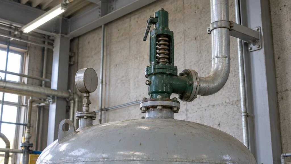
A Japanese supplier sends the safety valve data for a steam skid. The sheet lists a lift-type valve, a nominal size of 32A, a "relieving-capacity pressure" a little above the set pressure, and a coefficient written Kdr′ = 0.864. There is no API orifice letter, no 0.975, and the capacity comes from a table in a Japanese catalog. Your project's sizing checks follow API 520 and ASME, so you have to decide whether the supplier's numbers can be compared with yours at all.
The short answer: Japanese makers size steam safety valves with an equation that has the same basic form as API 520's, but with different coefficients, a different area basis, and Japanese legal rules for the required flow. The underlying physics is the same. What differs is which numbers go into the equation and who certifies them. If you mix API inputs with Japanese inputs, the result means nothing.
This guide explains how Japanese practice sequences the selection, shows the JIS-based capacity equation next to the API 520 steam equation, walks through a fictional sizing sheet, and ends with a checklist and questions for the supplier. It explains how to read and check the supplier's work. It is not a sizing procedure. The valve manufacturer, the equipment designer, and the code or regulation that applies at your site make the final decisions.
Contents
How Japanese Practice Sequences Safety Valve Selection
Japanese valve makers and plant engineers usually select a safety valve (安全弁, anzen-ben) in three steps: valve type, then set pressure, then nominal size. Each step fixes a condition for the next one, so a change in an early step, such as a different fluid, can change everything after it.
What you fix in one step becomes an input to the next.
Where the valve is installed (boiler, pressure vessel, or downstream of a pressure-reducing valve) changes which Japanese rules apply and how the required capacity is set.
Step 1: Valve Type
The maker's catalog lists, for each model, the fluids, temperatures, set-pressure range, and connections it covers. Standard models usually handle air, steam, and water. For special fluids, or for connections to a non-Japanese standard such as ASME flanges, the supplier has to ask the maker whether it can build the valve.
Japanese documents separate three valve names by service. A safety valve (安全弁) pops fully open and is mainly used for steam and gas. A relief valve (逃し弁, nigashi-ben) opens in proportion to the pressure rise and is mainly used for liquids. A safety relief valve (安全逃し弁, anzen-nigashi-ben) can serve both.
The fluid decides both the valve type and the bonnet (cap) style: open to the surroundings or closed.
Valve types and bonnets: VENN technical guide. Flammable and toxic service: Japan's Pressure Vessel Structural Standard, Article 64. For boilers, Article 62 of the Boiler Structural Standard requires a closed type or discharge to a safe place outside the boiler room for flammable vapor. Confirm temperature and pressure limits in the catalog for the actual model.
The choice that most affects sizing is full bore type (全量式, zenryo-shiki) versus lift-type (揚程式, yotei-shiki). The two calculate flow area differently, so you cannot compare capacity by nominal size alone.
| Full bore type (zenryo-shiki) | Lift-type (yotei-shiki) | |
|---|---|---|
| Opening | Opens fully in one step as pressure rises | Opens gradually |
| Capacity at the same nominal size | Higher | Lower than full bore type |
| Flow area used in the equation | Throat bore: πd²/4 | Seat bore and lift: πDL |
| Kdr′ (VENN's values) | 0.777 | 0.864 |
| Typical use | Relieving large steam flows | Smaller required capacities |
Note that the lift-type valve has the higher coefficient but the smaller area, so its capacity is still lower at the same size. A higher coefficient on a supplier's sheet does not mean a bigger valve. Japanese catalogs also offer models with or without a test lever, which lets an operator lift the valve by hand to check that it works. The user's maintenance practice decides which one to order.
Step 2: Set Pressure
The set pressure (設定圧力, settei atsuryoku) is specified on the order, and the maker adjusts the valve at its factory before shipping. In Japan, the Ordinance on Safety of Boilers and Pressure Vessels requires safety valves on boilers and Class 1 and Class 2 pressure vessels to be adjusted to operate at or below the maximum allowable working pressure (最高使用圧力, saiko shiyo atsuryoku, MAWP). Small boilers and small pressure vessels follow a separate rule (Article 93): 0.1 MPa, or in some cases the highest pressure in use. If components in the system have different MAWPs, including pumps and instruments along the piping, the lowest one sets the limit.
When a safety valve is fitted to equipment such as a heat exchanger, its set pressure becomes the highest pressure that equipment can reach. Depending on that pressure and the internal volume, the equipment may then count as a regulated pressure vessel (see Class 1 vs Class 2 Pressure Vessels in Japan). For how set pressure relates to MAWP, see Safety Valve Set Pressure vs. MAWP on Japanese Equipment.
The lower limit comes from the reseat pressure (吹止り圧力, fukidomari atsuryoku). A valve closes only after pressure has dropped somewhat below the point where it opened, and the difference is the blowdown (吹下り, fukisagari). VENN's catalog quotes the JIS B 8210:2025 limits for steam safety valves: 0.03 MPa (about 4.4 psi) at set pressures up to 0.4 MPa, and no more than 7% of set pressure above 0.4 MPa. If the reseat pressure is below operating pressure, a valve that has opened may not close fully during operation, and too small a gap between set and operating pressure can also cause leakage.
The set pressure has to keep this order intact, top to bottom (all gauge pressure).
Upper limit: Ordinance on Safety of Boilers and Pressure Vessels, Articles 28, 65, and 86. Blowdown: JIS B 8210:2025 as quoted in VENN's catalog. Margin between reseat and operating pressure: Spirax Sarco technical guidance.
The margin below the reseat pressure comes from maker guidance, not law. Spirax Sarco recommends at least 0.1 bar (0.01 MPa, about 1.5 psi) between reseat pressure and operating pressure. A Baker Hughes article states that operating pressure generally should not exceed 95% of set pressure to keep the seat tight. Both are guidelines; the actual blowdown of the chosen model decides. Pulsation can also push pressure above the set point for an instant and make the valve lift. Yoshitake's manual advises raising the set pressure or lowering the operating pressure in that case.
Two more items appear in Japanese documents. Constant back pressure on a conventional valve lowers its opening pressure by the amount of that back pressure, so the set pressure is raised by the same amount to compensate (Spirax Sarco). For a valve downstream of a pressure-reducing valve, VENN and Yoshitake each publish a table of how much to add to the reducing valve's setting. Their pressure bands and values differ: VENN's values are for metal-seated valves (soft-seated valves use other values), and Yoshitake's are guidelines for alarm safety valves. Ask which maker's table was used. In every case, the result must not exceed the protected equipment's MAWP. Once a valve is set, it usually cannot be changed on site: VENN treats field changes as not allowed in principle, and Yoshitake says resetting is done at the factory.
Step 3: Nominal Size From Required Capacity
Japanese sheets give valve size as a nominal size in millimeter designation (25A, 32A, and so on; 32A corresponds to NPS 1-1/4). The size follows from the required relieving capacity (必要吹出し量, hitsuyo fukidashi-ryo) at the set pressure. For equipment in Japan, the rules set minimum values by location.
The question at each location: what flows in, or is generated, and how much?
MHLW notice: "Partial Revision of the Boiler Structural Standard, etc." (Kihatsu 1107 No. 5, November 7, 2025). Downstream of a reducing valve, the basis depends on whether the downstream equipment can withstand upstream pressure.
For gas flowing into a pressure vessel through a pipe, the Japanese Ministry of Health, Labour and Welfare (MHLW) notice gives an inflow formula with assumed minimum velocities. Japan's Boiler Structural Standard also sets the number of safety valves on a boiler and how they are mounted. API-based practice does not use fixed velocities like these. Instead, it builds the required flow from the overpressure scenarios in API Standard 521, so the two methods can give different required flows for the same pipe.
0.0028 ≈ π/4 × 3600 ÷ 106 (converts mm to m and seconds to hours).
Downstream of a reducing valve, Japanese law often sets no flow. VENN suggests that an alarm-only valve can be one or two sizes smaller than the reducing valve, which corresponds to about 10% of its maximum flow. That figure only gives warning of a reducing-valve problem. If the downstream equipment cannot withstand the upstream pressure, the valve must relieve the flow with the reducing valve wide open (Spirax Sarco). When a Japanese drawing shows a small valve after a reducing station, ask which of the two purposes it serves.
The JIS Capacity Equation vs. API 520
Japanese steam safety valve catalogs state rated capacity with the equation below. VENN's catalog presents it as following JIS B 8210:2025. That standard, titled simply "Safety valves" (安全弁), is a modified adoption of ISO 4126-1:2013 and ISO 4126-7:2013. It is a product standard; its own text says it does not govern how valves are applied.
API 520 Part I sizes for steam with the following equation (SI units). Rearranged to give flow, it looks very close to the Japanese one.
The 5.25 in the Japanese equation and the 190.5 in API 520 are the same constant in different units (1000 ÷ 190.5 ≈ 5.25). The steam physics matches. The differences sit in the other terms.
| Item | Japanese practice (JIS B 8210 and catalogs) | API 520 / ASME practice |
|---|---|---|
| Standard's role | JIS B 8210:2025 is a product standard based on ISO 4126-1/-7 (modified). Japanese construction standards and MHLW notices govern application | API 520 Part I covers sizing and selection; API 521 covers overpressure scenarios; ASME BPVC covers certification and allowable overpressure |
| Coefficient | Kdr′ from the maker, a derated value applied to the actual flow area. In ISO 4126-1, the certified derated coefficient Kdr = Kd × 0.9 | Preliminary sizing: effective Kd = 0.975 with API 526 effective orifice areas. Final check: maker's certified K (0.9 × measured Kd) with actual area |
| Area and size designation | Actual area from seat bore and lift (lift-type) or throat bore (full bore type). Size by nominal size (25A, 32A) | Letter orifices (D to T) per API 526 for flanged valves; size by inlet × orifice × outlet |
| Relieving pressure | Vessel: larger of set × 1.1 or set + 0.020 MPa, plus 0.101. Boiler: larger of set × 1.03 or set + 0.015 MPa, plus 0.101 | ASME Section VIII single valve: pressure limited to MAWP + 10% or 3 psi (about 20.7 kPa), whichever is greater; 16% for multiple valves and 21% for fire |
| Steam property factor | C′ (maker's table by pressure) | KN (high pressure) and KSH (superheat) |
| Required flow basis | Legal minimums: boiler maximum evaporation; vessel maximum inflow or generation, with the MHLW inflow formula | Worst credible scenario from API 521 (blocked outlet, control valve failure, fire, and others) |
| Capacity source | Maker's capacity table by set pressure and nominal size | Maker's certified capacity (National Board NB-18 "Red Book" listing for ASME-stamped valves) |
The relieving-pressure rules look alike: a percentage of set pressure or a fixed pressure step, whichever is greater. Japan's 0.020 MPa for vessels is close to ASME's 3 psi, but the two are not the same rule. Japanese practice also has its own boiler rule. Do not substitute one for the other.
The main trap is mixing coefficient and area pairs. API 520's 0.975 belongs with the effective orifice areas in API 526. A Japanese Kdr′ belongs with the actual seat or throat area in that maker's dimension table. Baker Hughes's Consolidated sizing guide notes that API Kd values are higher than ASME-certified K values, while ASME-certified areas are larger than API 526 effective areas. Each pair only works with its own partner.
Reading a Japanese Sizing Sheet: A Fictional Example
The figures below are fictional. They show how a Japanese catalog calculation reads, using VENN's published coefficients and capacity table for its SL-37 series lift-type safety relief valves. They are not a design for any real installation.
- Fluid: saturated steam; valve on a Class 1 pressure vessel in Japan (P0 taken under the Pressure Vessel Structural Standard)
- Vessel MAWP: 0.50 MPa gauge (about 72.5 psig); operating pressure 0.40 MPa (about 58 psig)
- Required relieving capacity: 200 kg/h (about 440 lb/h), the maximum steam inflow to the vessel
- Valve type: steam service, open bonnet, with test lever; check whether a lift-type valve is large enough
First, the sheet checks that the set pressure (0.50 MPa, equal to MAWP) leaves room above operating pressure.
Next, it finds the required flow area. Set pressure is gauge, so P0 is converted to absolute pressure.
VENN's SL-37 dimension table lists a flow area of 43.3 mm² for 25A and 80.3 mm² for 32A. Against the required 69.1 mm², 25A falls short and 32A is enough. The capacity table gives the same answer.
The smallest size above the required 200 kg/h (dashed line) is 32A.
Units: kg/h. Values at set pressure 0.5 MPa from VENN's steam capacity table for SL-37 to SL-40, SL-43, and SL-44 (Pressure Vessel Structural Standard basis). The equation above gives 50.6, 86.2, 125.3, 232.4, 363.5, and 590.6, matching the table.
To see why you cannot cross-check this sheet with API numbers, plug the same flow and pressure into API 520 with Kd = 0.975 and all corrections at 1: 190.5 × 200 ÷ (651 × 0.975) ≈ 60.0 mm². That is an effective area to be matched against API 526 orifice letters, not against the 43.3 mm² and 80.3 mm² actual areas in a Japanese dimension table. Comparing 60.0 with 69.1 would compare two different area definitions.
The result also holds only for VENN's coefficients and table. Another maker or model has different coefficients and tables, so check the documents for the valve actually being bought. Safety valves are regulated safety devices. For equipment in Japan, the maker's documents and the applicable law decide, and questions can go to the local Labour Standards Inspection Office (労働基準監督署, rodo kijun kantokusho). For equipment installed outside Japan, the local code decides.
Related: Full-Bore vs Lift-Type Safety Valves: JIS Terms Explained
Japanese Rules That Affect Sizing and Layout
If the equipment will be installed and inspected in Japan, a few legal points show up on supplier drawings. For equipment shipped to another country, ask the supplier which of these they applied and whether the local code replaces them.
- Multiple valves: Under the Ordinance on Safety of Boilers and Pressure Vessels, when one valve is set at or below MAWP, the others on boilers and Class 1 and Class 2 vessels may be set up to 3% above MAWP. For example, with MAWP 0.70 MPa, a second valve may be set up to 0.721 MPa. A boiler superheater safety valve is set to open before the drum valves.
- No block valves: On Class 1 pressure vessels, the MHLW notice prohibits stop valves or other closing devices between the vessel and the safety valve, or on its discharge, in principle. Exceptions include two or more valves with an interlock that prevents closing them at the same time. A stop valve between the vessel and a safety valve installed downstream of a pressure-reducing valve is also permitted.
- Set pressure tolerance: For boiler steam safety valves, VENN lists the popping-pressure tolerance as ±0.015 MPa below 0.5 MPa set pressure and ±3% from 0.5 MPa to below 2.3 MPa.
For which Japanese vessels count as Class 1 or Class 2, see Class 1 vs Class 2 Pressure Vessels in Japan. If a rupture disc sits ahead of the valve, the combination capacity factor also enters the sizing; see Rupture Disc vs Relief Valve: Differences and Combined Use.
Checklist: Reviewing a Japanese Safety Valve Sizing Sheet
- Which code governs the sizing: Japanese construction standards, ASME, or another code? Which edition?
- Set pressure, with units and whether gauge or absolute (MPa G or MPa A)
- Relieving pressure P0: which rule (vessel 10%/0.020 MPa, boiler 3%/0.015 MPa, or ASME) and whether atmospheric pressure is added
- Coefficient: Kdr′ or certified K, its source (maker's own or certified), and that it is paired with actual area
- Flow area: lift-type (πDL) or full bore type (πd²/4), with the dimension-table value
- Steam correction: C′ value used, and whether the steam is superheated
- Required capacity: which basis (boiler evaporation, vessel inflow formula, reducing valve failure, other scenario) and how it was calculated
- Blowdown and reseat pressure, compared with normal operating pressure
- Back pressure at the outlet: atmospheric or header, and whether the setting was corrected
- Connections: nominal size (A), and JIS or ASME flange rating
- Whether the set pressure can be changed on site or only at the factory
- For export: whether the valve carries the certification your site code requires
For the full list of data to send with an order, see the checklist in Safety Valve Set Pressure vs. MAWP on Japanese Equipment.
Sample Inquiry to the Japanese Supplier
Subject: Safety valve sizing basis for [equipment tag]
Thank you for the safety valve data for [equipment name]. Our project checks relief devices against [API 520 / ASME Section VIII / local code]. Before we accept the selection, please confirm:
1. The code and edition you used to calculate the relieving pressure, and the relieving pressure value (absolute).
2. The coefficient of discharge and the flow area used, and whether the coefficient is certified or a maker's nominal value.
3. How you determined the required relieving capacity of [value] kg/h, including the scenario and any formula.
4. The blowdown and reseat pressure for this model at the specified set pressure.
5. Whether the valve has any certification (for example, ASME) that our site requires, and whether its capacity is listed.
6. Whether the set pressure can be adjusted on site, or must be reset at the factory.
Best regards,
[your name]
Japanese Terms on Safety Valve Sizing Sheets
| Japanese | Romaji | English |
|---|---|---|
| 安全弁 | anzen-ben | safety valve |
| 逃し弁/安全逃し弁 | nigashi-ben / anzen-nigashi-ben | relief valve / safety relief valve |
| 全量式/揚程式 | zenryo-shiki / yotei-shiki | full bore type / lift-type |
| 呼び径 | yobi-kei | nominal size |
| 設定圧力 | settei atsuryoku | set pressure |
| 吹出し圧力/吹始め圧力 | fukidashi atsuryoku / fukihajime atsuryoku | popping pressure / start-to-discharge pressure |
| 吹止り圧力 | fukidomari atsuryoku | reseat pressure |
| 吹下り | fukisagari | blowdown |
| 吹出し量決定圧力 | fukidashi-ryo kettei atsuryoku | relieving pressure (for capacity) |
| 必要吹出し量/公称吹出し量 | hitsuyo / kosho fukidashi-ryo | required / rated relieving capacity |
| 公称降格吹出し係数 | kosho kokaku fukidashi keisu | nominal derated coefficient of discharge |
| のど部の径/弁座口の径 | nodo-bu no kei / benza-guchi no kei | throat bore / seat bore |
| 最高使用圧力 | saiko shiyo atsuryoku | maximum allowable working pressure (MAWP) |
| 背圧 | haiatsu | back pressure |
Limits of This Guide
- This guide explains how to read and compare sizing work. It is not a sizing procedure, and its numbers are not design values.
- The Japanese equation, coefficients, and capacity values shown are VENN's published figures for specific models. Other makers and models differ by several percent or more.
- Liquid and gas service use different equations, and the relieving-pressure rule depends on which law or code applies.
- Japanese legal requirements apply to equipment installed in Japan. For equipment installed elsewhere, the local code and authority decide.
- The worked example is fictional.
FAQ
Is JIS B 8210 Equivalent to API 520 or ASME?
No. JIS B 8210:2025 is a product standard for safety valves, based on ISO 4126-1 and ISO 4126-7 with Japanese modifications. API 520 is a sizing and selection practice, and ASME covers certification and allowable overpressure. The steam capacity equations share the same constant, but the coefficients, area basis, and relieving-pressure rules differ.
Can I Size a Japanese Valve With API 520's 0.975?
Not against the maker's actual areas. The 0.975 is paired with API 526 effective orifice areas for preliminary sizing. Ask the Japanese maker for the coefficient and flow area that belong together for that model, and the capacity it guarantees.
What Is the Difference Between Popping Pressure and Set Pressure?
For steam safety valves, Japanese practice takes the popping pressure, where the valve snaps open, as the set pressure. For liquid and gas valves, VENN takes the start-to-discharge pressure, where a small flow first appears, as the set pressure.
Why Does a Japanese Sheet Show a Lift-Type Valve With a Higher Coefficient but Lower Capacity?
The coefficient applies to a different area. A lift-type valve uses the curtain area from seat bore and lift, which is smaller than a full bore type valve's throat area at the same nominal size. Compare rated capacities, not coefficients.
Can the Set Pressure Be Changed After Delivery?
Usually not on site. VENN treats field changes as not allowed in principle, and Yoshitake resets valves at its factory. If operating conditions change, ask the maker to reset the valve or replace it with one set to the new pressure.
Sources
- JSA: JIS B 8210:2025 preview (title, basis on ISO 4126-1/-7, scope; Japanese)
- ISO 4126-1:2004 (symbols: Kdr = Kd × 0.9)
- VENN: SF-17 catalog, applicable regulations and capacity equations (equation, coefficients, relieving pressure, JIS blowdown and tolerance; Japanese)
- VENN: SL-38 catalog (SL-37 series flow areas and capacity table; Japanese)
- VENN: Guide to automatic valves, safety valves (valve types, reducing-valve downstream setting and size, field changes; Japanese)
- Yoshitake: GP-1000 instruction manual (alarm safety valve setting after a reducing valve; Japanese)
- Yoshitake: AL-140 instruction manual (pulsation, factory resetting; Japanese)
- e-Gov: Ordinance on Safety of Boilers and Pressure Vessels, Articles 28, 65, 86 (Japanese)
- MHLW notice, Boiler Structural Standard Article 62 and Pressure Vessel Structural Standard Article 64 (required capacity, inflow formula, block valves; Japanese)
- MHLW: Pressure Vessel Structural Standard and Boiler Structural Standard (Japanese)
- fluids library: API 520 steam sizing implementation (equation constant 190.5, units, KN)
- Baker Hughes: Consolidated valve sizing technical specification (API Kd 0.975 with API 526 effective areas vs. ASME-certified K and areas)
- Emerson: Kunkle technical reference for safety relief products (16% for multiple valves, 21% for fire)
- Tata Consulting Engineers: ASME Section VIII pressure relief valve requirements (UG-125 overpressure limits)
- Spirax Sarco: Safety Valve Selection (reseat margin, back pressure)
- Spirax Sarco: Safety Valve Sizing (reducing valve failed open)
- Baker Hughes: Operational Basics of Safety Valves (Valve Magazine, May 2024; operating pressure up to 95% of set)
Original article in JapaneseThis guide is adapted from a MONOSCOPE article written for readers in Japan: 安全弁の選定方法|設定圧力の決め方と吹出し量の計算・呼び径の選び方
About the editor
 MONOSCOPE EditorFOUNDER & EDITOR
Spent about ten years at a plant equipment maker and a plant engineering company, proposing, designing, and commissioning equipment, then moved into web marketing. Now a web consultant for B2B manufacturers, helping them explain their products and technology. Licensed in Japan as an Energy Manager and a Third-Class Chief Electrical Engineer.
Has run an engineering blog since 2017 (500+ articles) and a Japanese YouTube channel with about 20,000 subscribers. Each English guide is written from the Japanese shop-floor point of view and checked against the cited standards.