Safety Valve Set Pressure vs. MAWP on Japanese Equipment
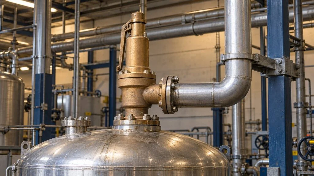
A steam pressure-reducing station or hot-water skid arrives from Japan. The vessel nameplate lists a 最高使用圧力 (saiko shiyo atsuryoku, maximum allowable working pressure, MAWP), and the safety valve carries its own set pressure. A few months into operation, the valve starts to weep, and someone on site suggests turning the set pressure up. Someone else asks whether setting it lower would keep a vessel out of Japan's pressure-vessel rules.
Both ideas start from the same mistake. Set pressure and MAWP mean different things, even when they carry the same number. The set pressure has to suit the MAWP of the equipment being protected, the applicable law or code, and the valve's own opening and reseating behavior. A correct setting is also not enough on its own: if the valve cannot discharge the flow that enters during an upset, pressure keeps rising.
This guide uses two examples, a steam pressure-reducing station and a blocked-in hot-water line, to show how the set pressure relates to MAWP, what the valve actually protects, when a valve is needed, and what to send with an order or inquiry. It explains what to check and who decides. It is not a procedure for choosing or changing a setting. Confirm every set pressure with the equipment designer, the valve manufacturer, and the code or regulation that applies to your site.
Contents
What a Safety Valve Does
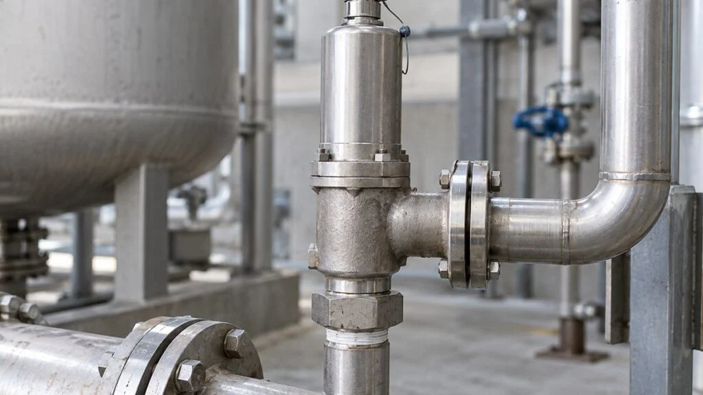
A safety valve (安全弁, anzen-ben) protects equipment and piping from overpressure. When pressure reaches the set value, it discharges fluid. It stays closed in normal service and, in the usual designs, closes again once the discharge has brought the pressure down.
In a spring-loaded valve, the spring pushes the disc closed while the fluid pushes it open. When pressure rises far enough, the disc lifts and opens a path from the inlet to the outlet.
Simplified spring-loaded valve. Opening characteristics and the effect of back pressure differ by valve type.
Japanese documents also use 逃し弁 (nigashi-ben, relief valve). Which term applies depends on the service fluid and operating characteristics, so do not move a valve made for steam onto a liquid line. Check the service fluids the manufacturer lists for that model. Full bore type valves (全量式, zenryo-shiki) and lift-type valves (揚程式, yotei-shiki) also have different flow paths and capacities, so you cannot compare capacity by connection size alone.
Related: Full-Bore vs Lift-Type Safety Valves: JIS Terms Explained
A pressure-reducing valve holds downstream pressure steady. A safety valve protects against abnormal overpressure. Keep the two jobs separate: one is normal control, the other keeps the system safe when that control fails. Pressure-switch alarms and trips play yet another role. How you combine normal control, alarm, supply shutoff, and mechanical relief depends on the failures you need to cover and on the equipment's requirements. For how a safety valve differs from a vent valve on a steam system, see Steam Vent Valve (Hojoben) vs. Safety and Bypass Valves.
Set Pressure vs. MAWP: Two Different Numbers
Start by writing down two values separately: the highest pressure the system reaches in normal operation, and the MAWP of the equipment being protected. The set pressure has to work between them once you account for the valve's opening and reseating behavior, the applicable law or code, and the set-pressure tolerance.
The set pressure (設定圧力, settei atsuryoku) is the pressure at which the valve is meant to start operating. MAWP is the pressure the equipment is allowed to run at. Even when the two are set to the same figure, they do not mean the same thing.
The valve does not always close just below the set pressure. Check the gap to operating pressure with the blowdown included.
The reseat pressure (吹止り圧力, fukidomari atsuryoku) is where the valve closes again after discharging. The difference between set pressure and reseat pressure is the blowdown. If normal operating pressure sits too close to the reseat pressure, a valve that has lifted once may not close again, and stable operation suffers.
A valve also does not deliver its full required flow the instant it starts to open. Check the pressure rise during discharge against what the equipment can tolerate, using the applicable law, the construction code, and the conditions of the valve's certification.
There is no rule where you add a fixed percentage to normal pressure and get the right setting for every system. If operating pressure swings so widely that no workable setting fits, the design needs another look, including the operating conditions and the equipment's pressure rating.
Use one pressure basis throughout. Do not mix gauge and absolute pressure, and confirm which one each drawing and datasheet uses.
Set Pressure Alone Does Not Decide a Vessel's Legal Class
In Japan, the safety valve setting alone does not decide whether a vessel is a regulated pressure vessel. The Order for Enforcement of the Industrial Safety and Health Act classifies vessels by use and working pressure, combined with internal volume and shell dimensions.
For Class 1 pressure vessels, the definition includes how the vessel is used, such as heating with a heat medium, generating steam, or heating to separate substances. Class 2 vessels, which hold gas, have their own conditions. No single pressure value applies to every use.
Check how the working pressure used for classification relates to the valve's set pressure against the equipment's design conditions. Turning down the setting on an existing valve is not evidence that the vessel is now exempt. Where a higher pressure is supplied from upstream, do not look only at the normal pressure after the reducing valve. Confirm in the design documents which pressure was adopted as the working condition, including supply-side failures and heating conditions.
For new equipment, confirm the legal class while use, temperature, pressure, and volume are still being decided. For existing equipment, start from the inspection certificate, the specification sheet, and the nameplate. If you change the operating conditions, check which procedures that change requires. Work from the vessel's use first, then check the criteria, including those for small pressure vessels and exemptions. For the classes and their thresholds, see Class 1 vs Class 2 Pressure Vessels in Japan.
Japan's Ordinance on Safety of Boilers and Pressure Vessels covers safety valves on boilers (Article 28) and on Class 1 pressure vessels (Article 65). The basic requirement in both is that the safety valve be adjusted to operate at or below the MAWP. Both articles also contain a conditional exception for installations with more than one safety valve. That exception does not mean a single valve may be set above MAWP. Match the specific article to the specific equipment. If another code also applies at your site, check its rules as well.
Check Every Component the Valve Protects
Next, go through every component inside the valve's protected zone. That means not just the tank, but also heat exchangers, pumps, instruments, and piping components. List the pressure limit of each one.
The protected zone depends on how the piping connects and which valves are open. List every component so the weakest limit is not missed.
Room-temperature catalog ratings can mislead. For flanges, valves, and other parts used at high temperature, check the pressure rating for that material at that temperature.
Keep "the pressure it survived in a pressure test" separate from "the pressure it can run at continuously." A test pressure applied only during testing is not a reason to set the safety valve above MAWP.
Pipe with the same nominal size does not always have the same pressure rating. Check material, wall thickness, and joint type together. The schedule number on the drawing is a starting point for wall thickness; see the JIS pipe schedule and thickness chart.
On a heat exchanger, check the primary and secondary sides separately, and consider what flows across if a tube or plate fails. Trace every path by which high-pressure fluid could reach the low-pressure side.
A block valve between the protected equipment and the safety valve can cut that equipment off from its protection. Mark the valve positions for operation and for maintenance on the piping drawings, and confirm in which states a relief path is still open.
Pressure drop in the discharge piping and pressure in the receiving header both create back pressure at the valve outlet. If a valve selected for discharge to atmosphere is connected to a recovery header without checking back pressure, its operation and capacity can change.
Route the outlet to a safe location where no one can be hit by steam or hot water, and allow for piping loads and reaction forces. Check the discharge point, drainage of condensate, and freeze protection against the installation manual for that valve model.
When a Safety Valve Is Needed
Whether you need a safety valve depends not only on normal operating pressure but on how high pressure can rise during an upset. First confirm which devices the law requires, then list every way a failure or an operating error could overpressure the system.
Two common cases are high supply pressure reaching the low-pressure side through a reducing station, and trapped liquid being heated. The causes differ, so the required capacity and the right valve type differ too.
High Supply Pressure Upstream of a Reducing Valve
Where steam or water pressure is reduced before use, the supply pressure can exceed the rating of downstream equipment. If the pressure-reducing valve (減圧弁, genatsu-ben) fails to close, fluid can keep flowing from the high-pressure side into piping that normally runs at low pressure.
Being able to pass the normal consumption rate does not make the safety valve big enough. Work out how much can flow downstream with the reducing valve in its assumed failure state and with the upstream conditions, and make sure the valve can discharge that flow.
Do not choose by connection size or normal consumption. Compare capacity under the assumed failure conditions.
Take a fictional plant where the steam inflow during the failure is assessed at 800 kg/h (about 1,760 lb/h). A candidate valve rated at 600 kg/h under the same pressure, temperature, and back-pressure conditions falls short.
A candidate rated at 1000 kg/h passes a simple capacity comparison against that inflow. This is not a recommended safety margin. Any capacity corrections or code requirements are separate conditions you build in when you select the valve.
Relieving capacity changes with set pressure and fluid condition, even at the same nominal size. For every figure in a capacity table, read the notes to see under which conditions it was measured or calculated.
Include flow paths created by how the plant is run, such as a reducing-valve bypass left open. If several supply paths can be open at the same time, do not stop after checking each normal flow on its own.
A safety valve is not a substitute for a reducing valve and should not be modulating continuously. A valve that is always discharging is a symptom to investigate. If it keeps lifting, record the upstream pressure, the pressure downstream of the reducing valve, the operating load, and when the discharge started. Check whether flow varies over time, keeping in mind the difference between steady and pulsating flow, and compare the records with actual load conditions.
Before raising the setting to stop the discharge, check for a failed reducing valve, seat leakage, and pressure-gauge error. Debris on the seat or a problem on the discharge side can also be the cause, so do not assume the pressure is simply too high.
Thermal Expansion in Blocked-In Liquid
When a liquid-full section of pipe is closed at both ends, the extra volume from a temperature rise has nowhere to go. Water barely compresses, so heating alone can raise pressure sharply, even with no steam entering.
Required relief flow differs between pure thermal expansion and cases where boiling or high-pressure inflow continues.
This is not limited to hot-water systems. It also happens in sections isolated for heat exchanger maintenance and in outdoor piping exposed to the sun. Even on idle equipment, check the piping drawings to see which closed valves would create a liquid-full section.
When thermal expansion of the liquid is the only cause, releasing the added volume can be enough to hold pressure down. That small-capacity logic does not apply when a high-pressure source keeps feeding the section or when heating generates steam.
An expansion tank absorbs normal expansion. Keep absorbing normal expansion and relieving abnormal pressure as two separate functions, and combine the protection each case needs. An expansion tank does nothing for a section once a valve between them is closed. Review the protected zone for cleaning, changeover, and shutdown valve positions, not only for steady operation.
Related: Hot Water Loop Not Flowing? Check Fill, Air, Valves, Pump
When choosing a liquid relief valve, know the temperature of the discharged liquid and where it goes. Hot water released to atmosphere can partly flash to steam as pressure drops, so locate the outlet where it cannot reach people or damage nearby equipment.
On site, check the set-pressure nameplate, the seal, and any corrosion or leakage, following the plant's shutdown and inspection procedures. A valve that looks fine is not proven to deliver its rated capacity, so also check the records of the required function tests and overhauls. Investigate "pressure does not come down" and "pressure comes down but the leak continues" as separate problems. Keeping records of each lift and of pressure makes it easier to tell undersizing, operating conditions, and seat problems apart.
Japanese valve maker Yoshitake, for example, generally asks for the set pressure to be specified at order or changed by returning the valve to the factory, and allows field adjustment only on certain models. Before any setting change, check the design conditions, the legal limits, and the instruction manual for that model.
Some systems use a rupture disc instead of, or together with, a relief valve. For how the two differ and how they are combined, see Rupture Disc vs Relief Valve: Differences and Combined Use.
Checklist: Data to Send With a Safety Valve Order or Inquiry
Send these items as one set. Capacity tables from different suppliers are often based on different conditions, and a complete set makes that easier to catch.
| Item | What to state |
|---|---|
| Fluid | Name and state (saturated steam, superheated steam, water, other liquid, gas) |
| Set pressure | Value, units, gauge or absolute; who decided it and on what basis |
| Protected equipment | MAWP of each component in the protected zone, at its design temperature |
| Operating temperature | Normal and maximum at the valve inlet |
| Required relief flow | Flow in the assumed upset (for example, reducing valve failed open), and how it was calculated |
| Connections | Inlet and outlet size, standard, and pressure rating |
| Discharge | To atmosphere or to a header; expected back pressure |
| Code and law | Which regulation or code applies at the installation site |
| Documents | Required inspections, test records, and certificates |
Questions to Ask the Japanese Supplier or Designer
- What is the MAWP of each component in the safety valve's protected zone, and at what temperature?
- Which overpressure scenario was the valve sized for (reducing-valve failure, bypass open, heat exchanger tube failure, blocked-in liquid)? What relief flow did you calculate?
- Under what conditions (pressure, temperature, back pressure) does the valve's rated capacity apply?
- What is the blowdown, and how far is the reseat pressure from our normal operating pressure?
- Which Japanese regulation or code did you apply, and does it change for our installation country?
- Can this model's set pressure be adjusted in the field, or must it go back to the factory? What records or seals are required after a change?
- Are there any block valves that can isolate equipment from the safety valve during operation or maintenance?
A sample inquiry you can adapt:
Subject: Safety valve set pressure on [equipment tag]
The safety valve on [tag] (set pressure [value] MPa G) has started to discharge during normal operation. Before we change anything, please confirm: (1) the MAWP and design temperature of each component it protects, (2) the overpressure scenario and relief flow used for sizing, (3) the blowdown, and (4) whether the set pressure may be adjusted on site for this model or must be reset at your factory. We will not change the setting until we receive your reply.
Limits of This Guide
- This guide explains how to think about set pressure. It does not give set pressure values, margins, or sizing formulas.
- Legal requirements differ by country, and in Japan by equipment class. The Japanese rules described here are for equipment in Japan; for equipment installed elsewhere, confirm which rules apply locally.
- Relief rates, allowable overpressure, and blowdown depend on the code, the valve type, and the manufacturer's certification. Confirm them with the valve maker.
- All plant numbers in this article are fictional.
FAQ
Is Safety Valve Set Pressure the Same as MAWP?
No. Even when they are set to the same figure, MAWP is the equipment's limit and set pressure is the valve's trigger point. Confirm that the setting meets the applicable law and the valve's characteristics, and that it sits far enough above normal operating pressure.
Can I Avoid Pressure Vessel Rules by Setting the Safety Valve Lower?
Not on the setting alone. In Japan the legal class depends on use, maximum gauge working pressure, and volume or dimensions, checked against the design and operating conditions you actually adopt.
Do Two Safety Valves With the Same Size Have the Same Capacity?
No. Capacity changes with valve type, fluid, and set pressure, so read the conditions behind each capacity table and compare valves against the required flow under the same conditions.
Related: Safety Valve Sizing in Japan: JIS B 8210 vs API 520
What Should I Do When a Safety Valve Will Not Stop Discharging?
Follow the plant's abnormal-condition procedure. Check whether pressure has actually dropped and whether supply is still coming in. Treat seat leakage after pressure has dropped as a separate problem, and do not hide the cause by raising the setting.
If There Is a Pressure-Reducing Valve, Do I Still Need a Safety Valve?
Do not assume the reducing valve is enough. If it fails, downstream equipment can be pushed past its rating. Decide on overpressure protection from the inflow during that failure and the applicable rules.
Sources
- Spirax Sarco: Safety Valves (spring-loaded valve basics)
- Spirax Sarco: Safety Valve Selection (operating pressure, set pressure, blowdown)
- Spirax Sarco: Safety Valve Sizing (failure conditions and relief capacity)
- Spirax Sarco: Safety Valve Installation (discharge piping, drainage, reaction forces)
- CGA PS-28 summary (overpressure from thermal expansion of trapped fluid; its US installation and requalification requirements are not applied in this article)
- e-Gov: Order for Enforcement of the Industrial Safety and Health Act, Article 1, pressure vessel definitions (Japanese)
- e-Gov: Ordinance on Safety of Boilers and Pressure Vessels, Articles 28 and 65 (Japanese)
- Yoshitake: FAQ on safety valves (setting, operation, service fluids; Japanese)
Original article in JapaneseThis guide is adapted from a MONOSCOPE article written for readers in Japan: 安全弁の設定圧力はどう決める?最高使用圧力・放出容量と設置が必要な場合
About the editor
 MONOSCOPE EditorFOUNDER & EDITOR
Spent about ten years at a plant equipment maker and a plant engineering company, proposing, designing, and commissioning equipment, then moved into web marketing. Now a web consultant for B2B manufacturers, helping them explain their products and technology. Licensed in Japan as an Energy Manager and a Third-Class Chief Electrical Engineer.
Has run an engineering blog since 2017 (500+ articles) and a Japanese YouTube channel with about 20,000 subscribers. Each English guide is written from the Japanese shop-floor point of view and checked against the cited standards.