Rupture Disc vs Relief Valve: Differences and Combined Use
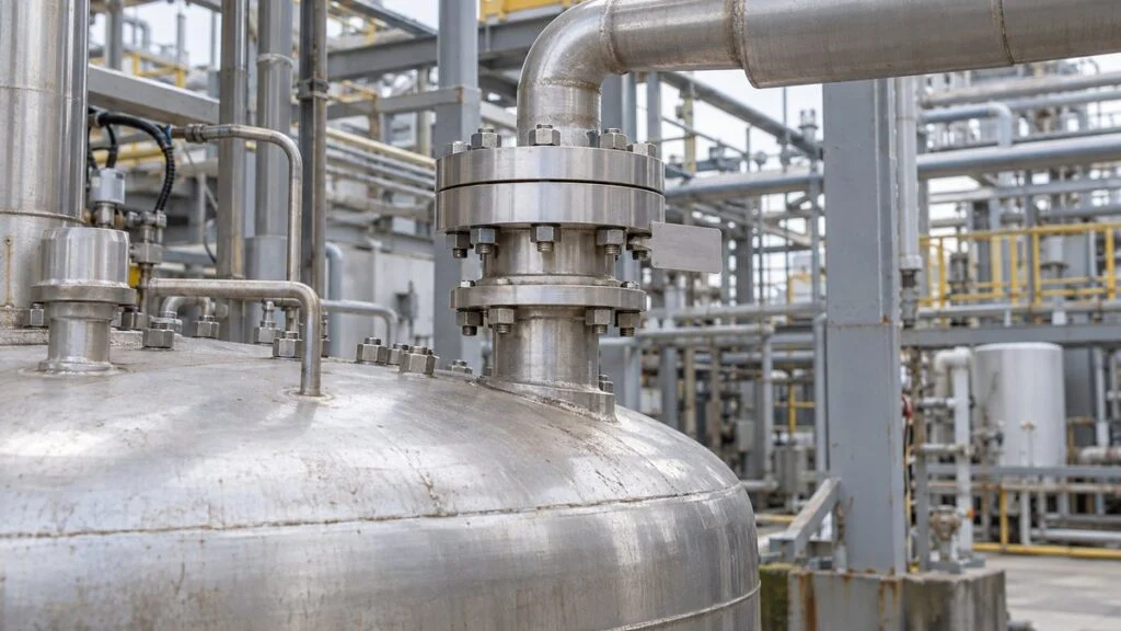
A reactor package arrives from a Japanese supplier. On the P&ID, a relief line leaves the vessel through a device labeled 破裂板 (haretsuban, rupture disc), followed by a 安全弁 (anzen-ben, safety valve). The datasheet lists a 破裂圧力 (haretsu atsuryoku, burst pressure) of 0.50 MPa. Before you accept the design, you need answers to three questions: Is 0.50 MPa a gauge pressure or a differential pressure? What happens if the discharge line holds some pressure? And why is there a rupture disc in front of the valve?
The short answer: a rupture disc is a thin plate that bursts at a specified differential pressure and temperature, and once it opens it stays open until someone replaces it. A relief valve opens on overpressure and closes again when the pressure drops. Both protect equipment from overpressure, and neither is meant to control normal operating pressure. (This guide uses "relief valve" as the general term and "safety valve" for the spring-loaded valve that Japanese documents call 安全弁.)
This guide explains how a rupture disc works, why backpressure changes the pressure at which it opens, how it compares with a spring-loaded relief valve, and what to check when the two are installed in series or in parallel. It ends with a checklist and questions you can send to the Japanese supplier.
Contents
- What Is a Rupture Disc?
- Differential Pressure and Backpressure: How to Read the Burst Pressure
- Rupture Disc vs. Relief Valve: The Key Differences
- Using a Rupture Disc with a Relief Valve: Series vs. Parallel
- Maintenance and Cost
- Installation and Operating Environment
- Checklist: Reviewing a Rupture Disc on a Japanese Datasheet
- Questions to Ask the Japanese Supplier
- Limits of This Guide
- FAQ
- Sources
What Is a Rupture Disc?
A rupture disc (also spelled rupture disk, and called a bursting disc in Europe) gives a vessel or pipe a pre-planned weak point. Installed on a reactor, pressure vessel, or line, it releases fluid before abnormal pressure can damage the equipment itself. Japanese documents use both 破裂板 and the katakana loanword ラプチャーディスク (rapucha disuku) for the same device.
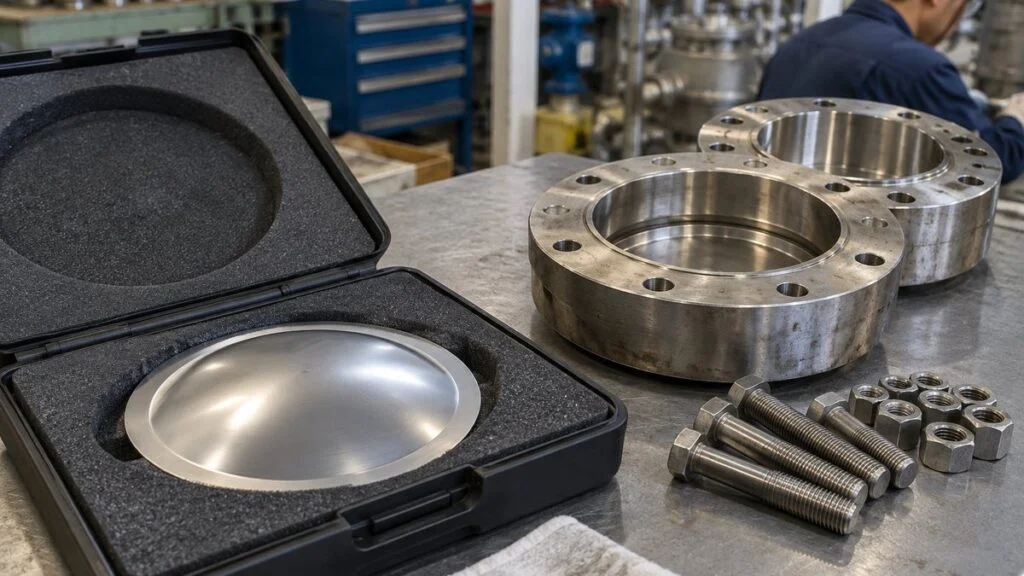
The disc is a thin sheet of metal or composite material, and its shape and material set the conditions at which it bursts. In a typical design, a dedicated holder clamps the edge of the disc, and the holder fits between two pipe flanges.
The shape of the holder and the way it is clamped also affect burst performance, so you cannot select a replacement by plate thickness alone. Treat the disc and holder combination specified by the manufacturer as one device.
The enlarged view shows the holder and the thin disc. Blue arrows show the flow after the disc bursts. In normal operation, the disc separates the process fluid from the outlet.
Some models do not use a separate holder. This figure shows a common design with a holder.
Differential Pressure and Backpressure: How to Read the Burst Pressure
What acts on the disc is the difference between the upstream and downstream pressures. A disc may be specified for discharge to atmosphere, but if pressure remains in the outlet line, you can no longer judge when it will burst from the upstream pressure alone.
Here is a simple, hypothetical example. Assume a burst differential pressure of 0.50 MPa (about 73 psi). With 0.50 MPaG upstream and atmospheric pressure downstream, the disc sees a 0.50 MPa difference. Express both sides as gauge pressure, so the downstream side is 0 MPaG.
Now suppose 0.10 MPa (about 15 psi) of backpressure builds up downstream. With the same 0.50 MPaG upstream, the differential drops to 0.40 MPa. In this simple model, the upstream pressure has to rise to 0.60 MPaG (about 87 psig) before the disc reaches its 0.50 MPa burst differential.
Assumes a burst differential pressure of 0.50 MPa. Both sides are gauge pressures.
Check upstream and downstream pressure together. Whether a disc can withstand backpressure and how backpressure shifts its burst point are two separate questions.
When you place an order, confirm whether the "burst pressure" on the datasheet means upstream pressure or differential pressure, and give the backpressure conditions at the same time. If the manufacturer was never told whether backpressure exists or how much it varies, no one on site should compensate by adding the backpressure to the specified setting.
Mixed pressure units are a common trap. If absolute and gauge pressure, or MPa and kPa, are mixed up, the inputs to the differential calculation are wrong before you start.
Burst Temperature, Tolerance, and Operating Ratio
A burst pressure always comes with a specified temperature (指定温度, shitei ondo) and a tolerance (許容差, kyoyosa), so a single number never fully describes the disc. Metal strength changes with temperature, so confirm with the manufacturer not only the normal fluid temperature but also how hot the disc will be during an overpressure event.
Keep the normal operating pressure well below the burst pressure, within the operating ratio (運転圧力比, unten atsuryoku-hi) that the model allows. Product literature defines the base of that ratio differently: the specified burst pressure, the lower limit of the manufacturing range, or the lower limit of the tolerance. You cannot apply a flat "90% of burst" rule.
One example: Fike Japan lists its SRX, a reverse-acting disc for gas and vapor service, as allowing operation up to 90% of the lower limit of the manufacturing range or tolerance. The same model cannot be used where liquid contacts the disc, and you cannot extend that figure to other reverse-acting discs.
The product guide from V-TEX, another Japanese rupture disc maker, also bases the operating ratio on the lower limit of the burst pressure tolerance. Before multiplying the pressure on the nameplate by a ratio, check how the tolerance and the ratio are defined. Then compare the resulting upper limit with the maximum normal operating pressure.
On the specification sheet, list normal operating pressure and burst pressure in separate fields, together with the ranges of temperature, backpressure, and pulsation, and how often pulsation occurs. Do not fill in unknown values with guesses. Collect data from startup and cleaning operations, and use it to agree on workable conditions with the manufacturer.
Rupture Disc vs. Relief Valve: The Key Differences
Both devices relieve abnormal overpressure, but the part that opens and the state after relief are different. The same connection size and set pressure do not guarantee the same relief capacity or the same way of returning to service.
How Each One Opens
A rupture disc opens the flow path by tearing or reversing, and the burst section does not return to its original shape. In a forward-acting (tension-type) disc, pressure stretches the plate. In a reverse-acting disc, pressure pushes against the convex side of the dome until it collapses. Each model then opens by its own mechanism.
In a typical spring-loaded safety valve, the valve opens when the force of the fluid on the valve disc overcomes the spring force. As relief lowers the pressure, the spring pushes the valve disc back, and the valve closes at its specified reseat pressure.
Left: one type of disc that opens along score lines. Right: a conceptual cross-section of a spring-loaded safety valve.
Actual opening shape, fragmentation, valve lift, and reseating follow the specifications of each model.
A rupture disc goes from first opening to a large flow area quickly, and that speed is one reason to use it. Speed alone does not handle every rapid pressure rise, though. If the flow path is too small for the required relief rate, vessel pressure keeps climbing even after the disc opens.
Some safety valves also open fully in one step, so a valve is not limited to slow pressure rises. The flow area depends on the valve design, such as lift-type versus full-bore safety valves.
Related: Full-Bore vs Lift-Type Safety Valves: JIS Terms Explained
| Item | Rupture disc | Safety valve |
|---|---|---|
| What opens | Thin plate bursts or reverses | Valve disc moves to open the flow path |
| After relief | Does not reclose; the disc must be replaced | Designed to reclose when pressure falls |
| Isolation in normal operation | The plate separates the process fluid from the outlet | Valve disc and seat form the seal |
| Maintenance focus | Corrosion, damage, pressure history, replacement interval | Operation, seat tightness, spring, seat condition |
| Common to both | Confirm fluid, temperature, pressure, backpressure, required relief rate, and the applicable code | |
Once a disc has burst, the opening cannot stop flow even after pressure drops. If the upstream side keeps supplying fluid, the design must also cover shutting off that supply and recovering the released fluid safely. Consider how long supply and discharge continue after the disc opens.
When to Use Each One
Engineers choose a rupture disc for its fast opening and because the plate keeps the process fluid sealed off during operation. Typical cases are isolating a relief valve inlet from corrosive or sticky fluids, and relieving overpressure where a mechanical valve is hard to use.
A safety valve is also a protective device for abnormal conditions, not a valve for adjusting everyday pressure. If a valve lifts every time demand changes, review the pressure control loop, including where pressure is measured and what the controller manipulates, not just the set pressure.
In steam systems, a control valve called a steam vent valve (hojoben) sometimes absorbs normal fluctuations by venting surplus steam. Keep that role separate from any plan that would make a safety valve or rupture disc operate frequently. For more, see Steam Vent Valve (Hojoben) vs. Safety and Bypass Valves.
Using a Rupture Disc with a Relief Valve: Series vs. Parallel
When you combine the two, first decide whether they go in series or in parallel, and what each arrangement is meant to improve. "Valve for normal upsets, disc for emergencies" is not the only pattern. In a series arrangement, both devices sit in the same relief path.
In series, check isolation and the pressure in the space between the devices. In parallel, check the role and relief capacity of each path. This is not a design drawing for set pressures or the number of devices.
If hazardous or flammable fluid is vented from the space between the devices, it also needs a safe recovery method. The actual configuration, including valves and instruments, comes from manufacturer documents and the applicable code.
Rupture Disc Upstream of a Relief Valve (Inlet Series)
In an inlet series arrangement, the rupture disc blocks the process fluid and protects the downstream relief valve from corrosion and debris. The risk is pressure in the space between them. If a pinhole leak or a temperature change lets pressure build there, the differential across the disc falls, and the disc may not burst at the intended upstream pressure.
For that reason, the space between the devices gets pressure indication or monitoring, plus a way to vent and recover any leakage safely. Decide in advance whether an instrument alone is enough, how it alarms, and what the operators do when a leak is found. ASME takes the same approach: BS&B's catalog, quoting the ASME code, states that this space must have a pressure gauge, try cock, free vent, or suitable telltale indicator so that disc rupture or leakage can be detected.
The disc must also not obstruct the relief valve when it opens, so check how it opens and whether it fragments. Do not assume the combination has the same capacity as the valve alone. Ask the manufacturer how the combination capacity factor is handled under your applicable code, and for any test or certification data. Fike and BS&B technical literature describes a default factor of 0.90 under most codes, meaning the combination is assumed to pass 90% of the valve's rated capacity, unless tests have certified a higher value for that specific disc and valve pair. Confirm the code and edition your project follows.
Rupture Disc and Relief Valve in Parallel
In a parallel arrangement, each device discharges through its own path. Check each device's opening conditions and the combined capacity against the upset scenarios you are protecting against. Also review the whole piping system for common causes that could disable both paths at once, such as a blocked inlet or high backpressure at the outlet.
Size for the Upset Scenario, Not the Moment the Disc Opens
If a reactor loses cooling, the remaining reaction heat can keep generating vapor. Look beyond the moment the disc opens: after feed and heating stop, what is still in the vessel, and how long must relief continue?
Thermal expansion of liquid trapped in a blocked-in line is a different case, and it does not need the same assumptions as a reactor. When you separate each cause into inflow, heat generation, vaporization, and expansion, the inputs for the required relief rate become clear. For a rupture disc, you need to confirm both the pressure at which it opens and that it can pass enough flow once open.
Related: Safety Valve Set Pressure vs. MAWP on Japanese Equipment
Maintenance and Cost
A rupture disc has no spring or sliding stem, so its construction is relatively simple. The thin plate, however, is affected by corrosion, scratches, and its temperature and pressure history. "No moving parts" does not mean "no failures and no inspection."
Pressure fluctuation does not automatically mean frequent replacement. Record the maximum pressure, the fluctuation range, and the number of cycles. Some models are designed for pulsating service, so check whether your conditions fall within the product's operating range and reflect that in the replacement plan.
Replace discs on the manufacturer's schedule even if they have not burst, and check whether a disc can stay in service after an abnormal pressure event or a pressure test. V-TEX recommends yearly replacement under normal conditions, but that is not a service-life figure that applies to every product.
Replacement work is done with the inflow isolated and residual pressure and liquid removed, following the site's own procedures. A burst disc does not mean the whole line is free of pressure or liquid. The torn edges are sharp, so handle them with suitable protective gloves, not bare hands.
Matching the replacement, preventing damage, and confirming direction and bolting go together. Torque values come from the instruction manual for each model.
Once the clamping of the disc edge has been loosened, do not judge the disc reusable by its appearance. Reinstalling a complete holder assembly has its own conditions; check them separately.
Removing a disc and clamping it again can change the stress at its edge and affect burst performance. Some products prohibit reuse even if the disc has not burst, so do not plan inspections that take the disc out and put the same one back.
Some designs, such as pre-torqued types, allow a complete holder assembly to be removed from and reinstalled in the line, as long as the bolts clamping the disc stay untouched and the assembly shows no damage. Use the instruction manual to tell the difference between reassembling the disc itself and reinstalling an assembly that keeps its clamping intact.
A safety valve can reclose, but after it lifts you still need to check seat tightness, debris on the seat, and the condition of the spring and other parts. If you put it back in service without removing the cause of frequent lifting, it will keep leaking or lifting. Investigate the process problem and the condition of the protective device separately.
Compare costs on more than the price of the disc: downtime, recovery and treatment of released fluid, spare parts, replacement labor, and inspection. Isolating a relief valve from a corrosive fluid can reduce its maintenance, but the series arrangement adds monitoring instruments and disc replacement work.
When a disc bursts, record more than the upstream pressure history: outlet pressure and temperature, operator actions, and the condition of the burst disc. If it seems to have burst below its rating, check differences in measurement location and instrument response before blaming a defective disc.
Before restart, remove the cause of the pressure rise and confirm that the relief path and the monitoring of the space between devices work. Check spare discs against the approved specification as well. A disc with a different model or specified temperature is not a substitute, even if it is in stock.
The connection between the holder and the piping also needs clear responsibilities. Decide who supplies the gaskets and bolts and which identification number you will use to order spare discs, so the unit can be restored quickly. See Mating Flange (Companion Flange): Who Supplies It?
Installation and Operating Environment
In corrosive or high-temperature service, check corrosion resistance and temperature limits for the disc, the holder, and the seals. The same material name can behave differently depending on fluid concentration and temperature, and the presence or absence of a surface treatment alone does not prove suitability.
Whether the device will relieve liquid, gas, or two-phase flow also matters. A model that must not contact liquid cannot be moved to a liquid line. If vapor can condense and collect as liquid, tell the manufacturer the conditions during startup and shutdown, not only in normal operation.
Where vacuum or reverse differential pressure can occur, confirm that the model handles it and whether it needs a vacuum support. Withstanding vacuum and bursting in the forward direction at the specified conditions are two separate requirements, so do not finish the selection after checking only one of them.
Which regulations and codes apply depends on the application, pressure, volume, and other factors. In Japan, pressure vessels are classified under the Industrial Safety and Health Act. Confirm the rules that apply to your equipment and its design documents, and do not mix set-pressure criteria from different classes or codes. See Class 1 vs Class 2 Pressure Vessels in Japan.
Check both the rupture disc burst pressure and the relief valve set pressure against the operating limits of the equipment they protect. As with the relationship between relief valve set pressure and maximum allowable working pressure, you cannot set them by adding a fixed percentage to normal pressure.
For the mounting flanges, match nominal size, pressure class, facing, dimensions, and gasket. Bolt holes that happen to line up do not prove the connection is acceptable. See JIS vs ASME (ANSI) vs JPI Flanges: How to Match Them.
If the discharge point is dangerous, depressurizing the vessel does not make the equipment safe. Collect and treat toxic or flammable fluids properly, and design the discharge point and supports for hot fluid jets, noise, and reaction forces on the piping.
Long discharge piping, many bends, or routing through other equipment can cause enough pressure drop to reduce relief capacity. Do not look only at the disc's flow area; check capacity and backpressure from inlet to outlet as one system.
Rainwater or condensate collecting at the outlet can interfere with operation through backpressure or freezing. Record on the drawings, as items for post-installation inspection, any blockage of the discharge point, pressure feeding back from a shared header, and loads from surrounding piping.
Explosion Venting Is a Different Problem
No one can claim that any rupture disc suits a location with explosion hazards. Overpressure protection for a reactor and explosion venting for dust or gas explosions deal with different phenomena and different equipment conditions.
For explosion venting on dust collectors or silos, the issue is not only the vent area but also where the flame and ejected material go. Knowing how to select a standard piping rupture disc is not enough to choose a device for this job; explosion venting needs its own study based on the explosion characteristics and the strength of the equipment. Fike Japan, for example, treats rupture discs and explosion protection as separate product lines. Start by defining which abnormal event you are protecting against.
Checklist: Reviewing a Rupture Disc on a Japanese Datasheet
- Burst pressure: gauge or differential? Units (MPa, MPaG, kPa) and whether absolute or gauge
- Specified temperature at burst, and the expected disc temperature during an overpressure event
- Burst tolerance and manufacturing range, and how the operating ratio is defined for this model
- Maximum normal operating pressure, pulsation range, and number of cycles
- Backpressure: present or not, normal value, range, and whether it exists at the moment of burst
- Vacuum or reverse pressure, and whether a vacuum support is needed
- Fluid state at the disc: liquid, gas, vapor, or two-phase, including startup and shutdown
- Disc type (forward-acting or reverse-acting), fragmentation behavior, and flow direction marking
- Disc and holder as a matched set from the same manufacturer, with model and part numbers
- For series installation: monitoring of the space between the disc and valve, alarm and leak response, and the combination capacity factor
- For parallel installation: role and capacity of each path, and common causes that could disable both
- Required relief rate by upset scenario, and capacity of the whole discharge line
- Discharge destination, recovery or treatment, reaction forces, drainage, and freezing
- Replacement interval, rules on reuse, and spare disc ordering information
- Applicable code or regulation (Japanese law, ASME, or other) and which edition
Questions to Ask the Japanese Supplier
You can adapt this sample email when the datasheet leaves gaps. Replace the placeholders with your own details.
Subject: Rupture disc data for [tag number / equipment name]
Dear [name],
Thank you for the documents for [equipment name]. Before we approve the relief system, could you confirm the following for rupture disc [tag number]?
1. Is the burst pressure of [value] stated as upstream gauge pressure or as differential pressure? What is the specified burst temperature?
2. What are the burst tolerance and manufacturing range, and how is the allowable operating ratio defined for this model?
3. What backpressure did you assume (normal value, range, and at the time of burst)? Is a vacuum support included?
4. For the disc installed upstream of the safety valve: how is the space between them monitored, and what combination capacity factor did you use? Please send any certification data.
5. Is the disc non-fragmenting, and which way is the flow direction marked?
6. What is the recommended replacement interval, and can the holder assembly be removed and reinstalled without replacing the disc?
7. Please provide the manufacturer, model, and part numbers for the disc and holder so we can order spares.
Best regards,
[your name]
A short Japanese term list helps when you read the supplier's reply.
| Japanese | Romaji | English |
|---|---|---|
| 破裂板/ラプチャーディスク | haretsuban / rapucha disuku | rupture disc |
| 安全弁 | anzen-ben | safety valve |
| 破裂圧力 | haretsu atsuryoku | burst pressure |
| 指定温度 | shitei ondo | specified (burst) temperature |
| 許容差 | kyoyosa | tolerance |
| 運転圧力比 | unten atsuryoku-hi | operating ratio |
| 常用圧力 | joyo atsuryoku | normal operating pressure |
| 背圧 | haiatsu | backpressure |
| 一次側/二次側 | ichiji-gawa / niji-gawa | upstream / downstream |
| 引張型/反転型 | hippari-gata / hanten-gata | forward-acting (tension) / reverse-acting |
| 吹止り圧力 | fukidomari atsuryoku | reseat pressure |
Limits of This Guide
This article explains principles and what to check. It is not a sizing method or a work procedure. Operating ratios, tolerances, replacement intervals, and reuse rules differ by manufacturer and model, and the numbers in the examples are hypothetical. The applicable code (Japanese regulations, ASME, ISO 4126, or others) and its edition decide the final requirements. Confirm every value with the manufacturer's drawings, instruction manual, and the project's code engineer.
FAQ
Can a Rupture Disc Replace a Relief Valve?
Sometimes a rupture disc alone provides overpressure protection, but you cannot simply swap an existing safety valve for a disc of the same size. Review the design against the applicable code, the relief capacity, and how supply shutoff and fluid recovery will work without a valve that recloses.
If a Rupture Disc Hasn't Burst, Can It Stay in Service Indefinitely?
No. Corrosion, damage, and pressure and temperature history change performance even without a burst, so replace discs according to the manufacturer's instructions and your operating conditions. Record the installation date, model and identification number, any abnormal events, and the next replacement date, and do not extend the interval just because the disc looks fine.
If a Disc Is Rated for Backpressure, Can I Ignore Backpressure?
No. Resisting reverse pressure without damage and the differential at which the disc bursts in the forward direction are separate properties. Give the manufacturer the backpressure value, its variation, and whether it is present at the time of burst, and confirm that the required upstream burst condition still holds.
Do Rupture Discs Always Fragment When They Burst?
No. Fragmentation depends on the model, and some products are designed to be non-fragmenting. When the disc sits upstream of a safety valve, choose a combination in which neither fragments nor the opened disc can obstruct the valve or the flow path.
Does a Larger Size Guarantee Enough Relief Capacity?
No. Capacity depends on the fluid state, temperature, relieving pressure and backpressure, and piping resistance as well as size. Calculate the flow you must relieve in each upset scenario, and compare it with what the device and discharge piping can pass under those conditions.
Sources
- V-TEX: Rupture disc construction and specifications by model (Japanese)
- V-TEX: How to read the specification table (Japanese)
- V-TEX: Rupture disc product guide (Japanese, PDF)
- V-TEX: User's guide, covering backpressure, orientation, handling, and maintenance (Japanese, PDF)
- V-TEX: Burst pressure and temperature (Japanese, PDF)
- V-TEX: Handling, maintenance, and quality (Japanese)
- V-TEX: Notes on inspecting reverse-acting discs (Japanese, PDF)
- Fike Japan: SRX reverse-acting rupture disc (Japanese)
- Fike Japan: Rupture disc catalog, including series and parallel installation (Japanese, PDF)
- Fike Japan: Explosion protection (Japanese)
- Fike: Technical bulletin on rupture discs used with pressure relief valves
- BS&B: Capacity factors
- BS&B: Rupture discs for safety relief valve isolation (PDF)
Original article in JapaneseThis guide is adapted from a MONOSCOPE article written for readers in Japan: ラプチャーディスクの設置目的と安全弁との違い|差圧・背圧と併用の注意点
About the editor
 MONOSCOPE EditorFOUNDER & EDITOR
Spent about ten years at a plant equipment maker and a plant engineering company, proposing, designing, and commissioning equipment, then moved into web marketing. Now a web consultant for B2B manufacturers, helping them explain their products and technology. Licensed in Japan as an Energy Manager and a Third-Class Chief Electrical Engineer.
Has run an engineering blog since 2017 (500+ articles) and a Japanese YouTube channel with about 20,000 subscribers. Each English guide is written from the Japanese shop-floor point of view and checked against the cited standards.