Steam Vent Valve (Hojoben) vs. Safety and Bypass Valves
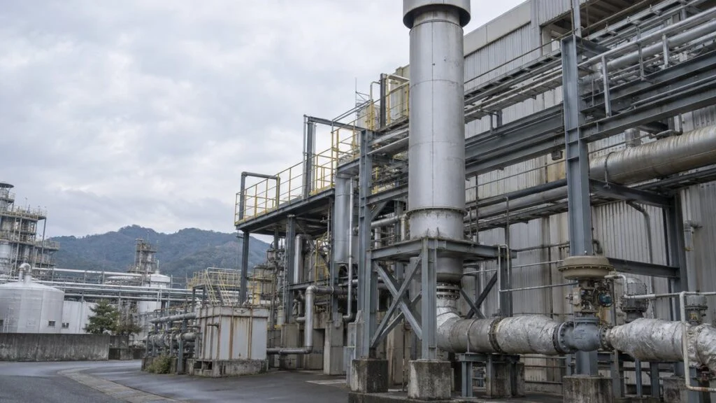
You are reviewing the P&ID or control narrative for a boiler or steam turbine package from a Japanese supplier, and one valve on a branch off the main steam line is labeled 放蒸弁 (hojoben). In the plant, operators notice that it opens every time a process unit shuts down, and someone asks whether it is a safety valve, whether it can be closed to save steam, or whether its setpoint can simply be raised.
Short answer: a hojoben is a steam vent valve. It is a control valve that releases surplus steam to hold down rising upstream pressure, usually when a large steam user suddenly stops. A boiler cannot stop making steam the instant you cut the fuel, and the vent valve covers that lag, which reduces how often the safety valves lift during normal operating swings. It does not replace the safety valves, which remain the final overpressure protection.
This guide uses a main steam line as the example. It covers how a steam vent valve works, how it differs from safety valves, pressure-reducing valves, and turbine bypass valves, when it opens, and how much steam and heat venting costs. It ends with a checklist and a list of questions to send to the Japanese supplier.
Contents
What Is a Hojoben (Steam Vent Valve)?
A steam vent valve sits on a discharge line that branches off the steam piping, and it changes its opening according to upstream pressure. In Japanese, hojoben (放蒸弁) literally means "steam-release valve." English documents describe the same function with names such as steam vent valve, steam dump valve, or, in power plants, sky vent valve. The name on your drawings depends on the supplier, so confirm the function from the P&ID and the control description rather than from the name alone.
You find these valves on main steam lines that vent surplus steam to atmosphere, and also on process steam systems in factories. Main steam is the steam a boiler produces and sends to a turbine or other users. Because the vent line is a separate branch from the header that feeds the users, the system has somewhere to send steam when demand suddenly drops.
Figure 1: Main Steam Header, Vent Line, and Pressure Signal Path
Solid lines are steam; dashed lines are measurement and control signals. The vent valve and the safety valve sit on separate branches.
Conceptual diagram. The number and location of safety valves, their discharge points, and any trip signals depend on the plant design. PT = pressure transmitter.
How It Controls Pressure
A pressure transmitter measures upstream pressure, and a pressure controller compares it with the setpoint to calculate the valve opening it needs. As pressure rises, the controller drives the valve further open, more steam leaves through the vent line, and the rise upstream slows down.
When demand returns or the boiler's steam output falls, the surplus shrinks and the valve moves back toward closed. Unlike an on/off valve, a steam vent valve normally throttles: it runs at intermediate openings to match the amount of steam it releases.
On a pneumatic valve, the actuator takes the control signal and moves the stem to change the flow path. A positioner keeps the actual stem position in line with the commanded opening, so there is a small position loop running inside the larger pressure loop.
If pressure will not come down, start by looking at the command and the actual valve position separately. The two cases call for different checks: a command that is not increasing usually sends you back to the measurement and the controller, while a command that increases with no valve movement usually sends you to the actuator, positioner, or valve itself. For position feedback alarms on Japanese valve systems, see our guide to the jutai (valve travel) alarm.
Vent Noise and the Silencer
When high-pressure steam is released to atmosphere, it expands violently through the narrow flow path in the valve and near the outlet, and that flow is very loud. For that reason, vent lines are often fitted with a silencer.
A silencer reduces discharge noise by breaking the steam into many small jets and giving it room to expand. It is selected for a specific flow rate and inlet condition; simply fitting a large pipe to the end of the vent line does not do the same job.
Figure 2: Conceptual Cross-Section of a Vent Valve Seat and Silencer
The gap at the valve seat sets the flow; the perforated section of the silencer breaks up the jet.
Orange arrows show flow. Steam passes through the seat opening, cannot escape through the closed top of the perforated tube, and exits through the side holes to atmosphere. This section only shows the function; actual shape, number of stages, and whether sound-absorbing material is used vary by model.
When sizing, treat the vent valve, the piping to the silencer, and the silencer as one discharge system. Any back pressure at the valve outlet reduces the pressure drop across the valve, so the valve's own capacity does not tell you how much the system can release.
The valve's flow coefficient (Cv) is the starting point for checking the required flow. For steam, you also need the inlet pressure and temperature and the outlet pressure, because the capacity calculation must treat steam as a compressible fluid.
The discharge point brings hot steam and noise, and the piping also takes a reaction force from the jet. Follow the design drawings and the manufacturer's instruction manual for locating the outlet away from walkways, supporting the piping, and draining low points.
Steam Vent Valve vs. Safety Valve, PRV, and Turbine Bypass Valve
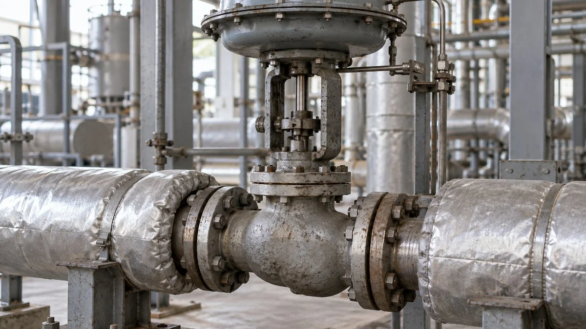
The job of a steam vent valve is to absorb pressure swings during operation and keep the steam system stable. It releases surplus steam that normal combustion control cannot absorb quickly enough, which cuts down unnecessary safety valve lifts.
A vent valve controls pressure; a safety valve protects equipment from overpressure. Having a vent valve on the line does not take over the protective function required of the safety valves.
A safety valve is the final protective device: it releases fluid automatically when pressure reaches its set value. Nothing done for operating convenience should prevent it from lifting, and after it lifts, the cause of the pressure rise and the condition of the valve should be investigated. A vent valve, by contrast, depends on a sensor, a controller, and an actuator working together, and a fault in any of them affects how it behaves.
Related: Full-Bore vs Lift-Type Safety Valves: JIS Terms Explained
| Valve | What it controls or protects | Where the steam goes |
|---|---|---|
| Steam vent valve (hojoben) | Holds down upstream pressure by releasing surplus steam during operation | To atmosphere, usually through a silencer |
| Safety valve | Final protection against overpressure; opens automatically at its set pressure | To its own discharge point |
| Pressure-reducing valve (PRV) | Controls downstream pressure while supplying steam to users | To the steam users |
| Turbine bypass valve | Opens a path around the turbine | To a condenser (where so designed), so the steam is recovered as water |
Coordinating Setpoints Between Normal Operation and Overpressure Protection
The basic principle: venting starts above the boiler's normal operating pressure and controls pressure before it reaches the safety valve set pressure. Coordination is not just about putting the pressures in the right order. The size of normal pressure swings and the response speed of each valve also have to fit.
Figure 3: Pressure Bands and Which Function Covers Each
Higher pressure at the top. This is not a scale of actual setpoints or margins.
The safety valve's reseat pressure also has to be considered. Actual setpoints are determined by the applicable regulations, the allowable pressure of the protected equipment, and the approved equipment and control specifications.
If the vent setpoint is too close to normal operating pressure, the plant ends up dumping steam on small fluctuations. If it is too close to the safety valve set pressure, pressure can reach the safety valve's operating range while the vent valve is still opening.
A safety valve also does not necessarily reseat at the same pressure at which it started to lift; the difference is called blowdown. Spirax Sarco's safety valve selection guidance, for example, recommends setting the safety valve far enough above normal operating pressure that it can reseat above that pressure after discharging.
When operators see frequent venting, avoid simply raising the setpoint. First compare normal pressure fluctuations, changes in steam demand, the transmitter reading, and the actual valve movement, and then choose a fix that matches the cause.
Pressure-Reducing Valves and Turbine Bypass Valves
A pressure-reducing valve controls downstream (secondary) pressure while it delivers steam to users. A vent valve controls upstream (primary) pressure by getting rid of surplus steam. The two watch different pressures and send steam to different places.
A turbine bypass valve opens a path that lets steam go around the turbine. Where the bypass goes to a condenser, the steam is recovered as water instead of being lost to atmosphere, which is the key difference from a vent line. A condenser, however, can only accept limited steam flow, pressure, and temperature, so how the bypass and vent valves share the load is decided in the design of the whole system, condenser included.
When Does a Steam Vent Valve Open?
On a main steam line, venting is needed when steam use suddenly drops below steam production. The typical cases are a large, sudden load drop, a turbine trip, and operation below the boiler's minimum stable load.
Sudden Load Drops
When steam use falls, for example at the end of a heating step, the steam that was flowing to users is left over in the piping. Combustion control reduces firing, but until steam output catches up there is still a gap, and pressure rises.
The vent valve releases that surplus and softens the rise. Among load changes, it is mainly sudden drops in demand that push pressure up; a sudden increase in demand causes the opposite problem, steam shortage and falling pressure.
When reviewing operating records, do not look at pressure alone. Put steam flow and the firing-rate command on the same time axis. If venting lines up with the time a process changes over, you can trace how the users' shutdown and the boiler's response interact.
When checking the pressure transmitter signal, also confirm how the 4–20 mA signal maps to the measuring range. Do not rely only on the number on the control screen; check that the input range matches the actual pressure.
Related: 4-20 mA vs 1-5 V: Why Japanese Panels Use 250 Ω Inputs
Turbine Trips
A trip is an emergency shutdown that protects equipment when something goes wrong. When the turbine's inlet valves close quickly, a large steam user disappears at once, and main steam pressure tends to rise.
Even when the shutdown starts from something like a grid fault, what directly affects pressure is the interrupted steam flow. Do not infer vent valve behavior from the generator trip signal alone; read it together with the turbine valve movements.
Figure 4: The Gap Between Demand and Steam Output Right After a Turbine Trip
The inlet valves close at time 0. Until boiler output catches up, the surplus needs a path out.
Schematic in which demand drops to zero when the valves close. Apart from time 0, there is no scale for time or flow; the decline in steam output, vent flow, and valve response time do not represent values from a real plant.
Some plants do not wait for pressure to rise. They also use the trip signal to open the valve in advance. The required opening speed has to be achieved by the whole chain, including the actuator and signal processing, not just the valve body.
These commands are typically handled in the distributed control system (DCS) or similar. Pressure control and the emergency feed-forward command serve different purposes, so the control specification should also state which one takes priority.
During recovery, do not assume the vent valve returns to normal as soon as the trip is reset. Follow the actual restart conditions in the plant, including how they relate to turbine speed and inlet valve movement.
Demand Below the Boiler's Minimum Stable Load
Every boiler has a minimum load at which it can keep burning stably, and that limit depends on the fuel and the firing method. If demand stays below it while the boiler keeps running, there is not enough demand to take all the steam produced.
In that situation, the plant may need to vent the temporary surplus to hold pressure. This is not only an issue for solid-fuel boilers; with oil- or gas-fired units, too, check the minimum load and control range of the specific model.
If low demand lasts a long time, reduce venting by reviewing how many boilers are running and how load is shared between them. Where demand peaks and dips follow a regular cycle, a steam accumulator, which stores surplus energy in hot water, is another option. It fits applications where the charging time, the usable pressure range, and the required capacity all work out.
Related: Boilers in Japan: Legal Classes, Operator Licenses, Fuels
Worked Example: How Much Does Venting Cost?
Suppose a boiler's minimum stable steam output is 2.0 t/h (about 4,400 lb/h) and steam demand has dropped to 1.5 t/h (about 3,300 lb/h). With no heat storage and no other system to take steam, and with pressure held constant in steady state, the difference of 0.5 t/h is surplus. All values in this example are assumptions for illustration.
If this venting continues for 10 minutes, about 83.3 kg (about 184 lb) of steam is lost. Because the flow rate is per hour, convert the duration from minutes to hours before multiplying.
Now assume a specific enthalpy of 2,800 kJ/kg for the steam and 400 kJ/kg for the makeup water. Taking the heat needed to turn makeup water back into steam as the basis, the heat lost is the difference between the two multiplied by the vented mass.
Figure 5: Steam Balance for the Assumed 10 Minutes
The vent valve holds pressure, but the heat and water in the vented steam never reach the users.
| Destination | Flow | Mass in 10 min | Share of steam supplied |
|---|---|---|---|
| Supplied by boiler | 2.0 t/h | about 333.3 kg | 100% |
| Used by users | 1.5 t/h | 250 kg | 75% |
| Vented to atmosphere | 0.5 t/h | about 83.3 kg | 25% |
With the example's enthalpy difference of 2,400 kJ/kg, the vented steam carries 200 MJ. The percentages are not the fuel-cost loss or a boiler efficiency loss.
200 MJ (about 190,000 Btu) over 10 minutes is the same as throwing away about 333 kW of heat on average. To convert this into fuel, you also need the boiler efficiency and the fuel's heating value.
In a real calculation, take the specific enthalpy from the steam's pressure and temperature. This balance only shows the scale of the loss; it is a separate calculation from the pressure rise right after a trip or the valve capacity you need.
Checklist: When the Vent Valve Opens Too Often
Before changing anything, overlay the start time and duration of each venting event on the process operating log. Whether the valve is handling short, sharp changes or staying open throughout low-demand periods changes which fix comes first.
- Main steam pressure, steam demand, and boiler steam output over time
- Vent valve opening command and actual position, and the time of any trip signal
- The time the firing rate starts to drop, and whether the boiler reaches minimum load
- Signs of leakage after the valve closes, and changes in noise or vibration
- Transmitter range and 4–20 mA scaling versus the pressure shown on screen
Do not look for leaks by approaching hot sections, or move the stem of an operating valve by hand. Collect data from the installed instruments first, and inspect the valve itself only under the plant's shutdown and isolation procedures.
Questions to Ask the Japanese Supplier
If the boiler or turbine package came from Japan, these questions help you get the information that is usually spread across the P&ID, the control narrative, and the valve datasheet.
- What is the function of the valve tagged 放蒸弁 (hojoben): pressure control only, or also opened by a trip signal?
- What is its pressure setpoint and control band, and how are they coordinated with the safety valve set pressure and blowdown?
- Which signals open it (pressure, turbine trip, other interlocks), and which one has priority in the control logic?
- What is its fail position on loss of air or power, including any auxiliary circuits?
- What vent flow, inlet conditions, and back pressure were used to size the valve, the outlet piping, and the silencer?
- How do the vent valve and the turbine bypass valve share the load, and what are the condenser's limits?
- What conditions must be met before the valve returns to normal control after a trip is reset?
- What seat leakage class is specified, and how should leakage be checked?
Limits of This Guide
This article explains the general function. Valve names, setpoints, interlocks, and fail positions vary by plant, supplier, and project, so the drawings, control specifications, and manuals for your equipment take precedence. Safety valve settings and protective devices must follow the regulations and codes that apply where the plant is installed, and decisions about them belong to the responsible engineer and the equipment owner. The numbers in the worked example are illustrative only.
FAQ
Is it abnormal if the steam vent valve opens?
No, not if it opens as designed, for example during a sudden load drop or at startup and shutdown. If it stays open for long periods under conditions where it is normally closed, investigate the gap between demand and steam output and the state of the controls.
Can a vent valve replace the safety valve?
No. Installing a vent valve is not a reason to omit the protection a safety valve provides. Pressure control and overpressure protection are separate functions, and protective devices must be installed according to the regulations and specifications that apply to the equipment.
Does a steam vent valve always fail open on loss of air or power?
Not necessarily. The fail position is set by the plant design, including the actuator and auxiliary circuits. Do not assume it opens because of its name; check the fail action in the valve datasheet against the control conditions for loss of air and power.
If I can't see white steam at the outlet, is the valve not leaking?
You cannot tell whether the valve is fully closed just by looking at the discharge point. Leak checks use flow, temperature, and other data in addition to the position indication, following the method the plant has defined.
Can we stop venting to save energy?
Blocking venting that is needed to control pressure during operation is dangerous. To save energy, reduce the surplus at its source, by matching supply to demand or by storing heat, rather than closing off the discharge path.
To read a vent valve's behavior, look at both the steam producers and the steam users, not just the valve. Estimating losses from venting time and flow rate is also a practical first step in plant energy management.
Sources
- Vent valve application, high temperature, vibration, and seat leakage: Emerson, "Sky Vent Control Valve Solutions"
- Turbine bypass at turbine trip: Emerson, "Sempell Model 115 Turbine Bypass Valve"
- Role of safety valves: Sankyo Seisakusho, safety and relief valve technical information (Japanese)
- Operating pressure and blowdown margin for safety valves: Spirax Sarco, "Safety Valve Selection" (general setting principles only; no values from overseas codes are applied to Japanese installations)
- Silencer principle and construction: Miura Environmental Science Laboratory, silencer brochure (Japanese)
- Silencers for atmospheric steam discharge: SK Tech, atmospheric discharge silencers (Japanese)
- Steam demand fluctuation and heat storage: Spirax Sarco, "Steam Accumulators"
Original article in JapaneseThis guide is adapted from a MONOSCOPE article written for readers in Japan: 放蒸弁とは?役割と作動する状況、安全弁・バイパス弁との違い
About the editor
 MONOSCOPE EditorFOUNDER & EDITOR
Spent about ten years at a plant equipment maker and a plant engineering company, proposing, designing, and commissioning equipment, then moved into web marketing. Now a web consultant for B2B manufacturers, helping them explain their products and technology. Licensed in Japan as an Energy Manager and a Third-Class Chief Electrical Engineer.
Has run an engineering blog since 2017 (500+ articles) and a Japanese YouTube channel with about 20,000 subscribers. Each English guide is written from the Japanese shop-floor point of view and checked against the cited standards.