Plant North vs True North: PN Symbol on Japanese Drawings
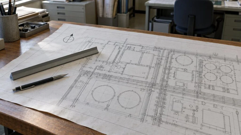
A plot plan arrives from a Japanese EPC contractor or equipment supplier. In one corner there is a circle marked 0°, 90°, 180°, and 270°, with "PN" at the top and a second arrow labeled "N" tilted off to one side. The vessel drawings give nozzle locations as angles, and nobody on your side is sure which "north" those angles are measured from.
The short answer: PN stands for plant north, a reference direction the project chooses for its drawings. It is not a direction on the globe. It is separate from true north (the north on a map) and from magnetic north (where a compass needle points). On Japanese plant drawings you may also see these written in kanji: 真北 (shinpoku, true north) and 磁北 (jihoku, magnetic north).
This guide covers how to read the PN symbol, how plant north differs from true and magnetic north, how a project typically sets PN, and what to check on the drawings you receive. It ends with a checklist and a ready-to-send query for the Japanese side.
Contents
What Is Plant North (PN)?
Plant north is the direction a plant project treats as "north" for all of its layout and equipment drawings. It is usually shown with a symbol like this:
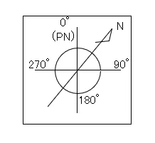
The 0° mark is plant north. The tilted arrow labeled N points to actual (true) north. Angles are read clockwise from 0° (PN): 90°, 180°, 270°. Drawings are usually laid out with 0° at the top of the sheet, so 90° is to the right, 180° is down, and 270° is to the left.
Why not just use compass directions? Because geographic directions alone make it hard to describe where equipment sits relative to other equipment. Take a plant site that runs from southwest to northeast:
Left: the site drawn with true north up. Right: plant north set along the site, so the site sits square on the sheet.
Illustrative example. Plant north here is 45° counterclockwise from true north.
On the left, every direction on the site falls somewhere between the compass points, which makes positions hard to describe in words. On the right, the project sets its own reference direction and numbers the angles 90°, 180°, and 270° clockwise from it. To put equipment B on the "south" side of equipment A, the instruction becomes "install B on the 180° side of A (relative to PN)," which leaves much less room for misunderstanding.
The site is rotated 45° from true north. With PN, each direction comes out as one clean number.
Same example as Figure 1: plant north is 45° counterclockwise from true north.
Plant north belongs on the plan views of the main equipment drawings, so anyone reading them can see which way each item faces relative to the plant as a whole.
Plant North vs. True North vs. Magnetic North
When a drawing says "north," it can mean one of three things: true north (TN), magnetic north (MN), or plant north (PN). True north and magnetic north are set by the earth. Plant north is set by people, one project at a time.
| True north (TN) | Magnetic north (MN) | Plant north (PN) | |
|---|---|---|---|
| What it is | North along the earth's axis of rotation (toward the North Pole); the north shown by map meridians | Where a compass needle points | A reference north chosen for each plant, usually to match the buildings and equipment rows |
| How it is fixed | Fixed for each location; does not change | Set by the earth's magnetic field; varies by location and shifts a little each year | Decided by the project at the start of design |
| Offset from true north | None (it is the reference) | In Japan, about 6–10° west | Angle θ, different for every plant |
| Main uses | Maps, surveying, building permits | Getting a rough bearing on site with a compass | Orientation of plot plans, equipment layouts, piping plans, and equipment drawings |
| How it appears on drawings | North arrow marked "N" or "TN" | Declination shown on topographic maps | 0° on the PN symbol, plus a note giving the angle to true north |
Here are all three on one drawing, with plant north at the top of the sheet:
The angle θ between PN and true north is chosen for each plant. The angle between true and magnetic north (the declination) depends on location and year.
Declination: GSI magnetic chart, 2020.0 values (westerly). It changes over time, so look up the current value for your site. θ is different for every plant.
Across Japan, magnetic north lies about 6–10° west of true north: about 10° in Sapporo and about 6° in Naha, based on GSI's 2020.0 values. If you check directions on a Japanese site with a compass, you need to allow for this offset. The declination drifts as the earth's magnetic field changes, so GSI updates its magnetic charts every five years. For a specific location, the value also appears on GSI's 1:25,000 topographic maps and its online GSI Maps service.
Plant north has no fixed link to either true or magnetic north. Projects usually set it to match the site and the main buildings. With PN at the top of the sheet, equipment positions can be described with simple angles: 0°, 90°, 180°, and 270°.
The angle θ between PN and true north is written next to the PN symbol on the plot plan and similar drawings. True north still matters in Japan: building regulations such as the north-side slant-plane height limit and the shadow restrictions are measured from true north, so building permit drawings must show it.
How a Project Sets Plant North
Plant north is fixed on the overall plot plan early in design, and every plan view drawn after that uses the same orientation. If PN shifts from one drawing to the next, equipment can end up installed facing the wrong way, or piping connections (tie-ins) can be mismatched.
The starting point is always the project's drawing standard or the coordinates of existing facilities. When PN is being set for the first time, the process generally looks like this:
Set 0° to match the buildings, then record the angle to true north on the drawings.
A piping design reference outside Japan (Wermac) gives a rule of thumb of keeping PN within 45° of true north. One of the four directions square to the long sides always falls within 45°.
Plant coordinates usually follow PN as well: the PN direction is "north" (N) and 90° clockwise from it is "east" (E), so a point is given as, for example, "N 120.000, E 85.000." Keep the coordinate grid and the PN direction aligned.
The layout itself is worked out from material flow, access, and maintenance space, as with any factory layout. PN is the tool for communicating the agreed layout correctly on paper. In CAD or Visio, keeping the top of the page at 0° (PN) lets you specify equipment rotation directly as a drawing angle.
What to Check on Drawings You Receive
When drawings come in, don't stop at confirming that a PN symbol is there. Cross-check these four points:
Look beyond the PN symbol: the angle note, the coordinates, and the orientation on equipment drawings all need to agree.
If the project specification defines its own drawing conventions, those take precedence.
Cylindrical equipment such as tanks and columns is where this matters most. Nozzle positions are given as angles, so if 0° on the equipment drawing does not match PN, every piping connection point on the vessel ends up rotated.
Nozzle orientation also fixes where the companion flanges supplied by the piping side must sit. If the orientation on a supplier's approval drawing (shonin-zu) differs from what was specified, confirm it as a deviation on the deviation list.
A P&ID (piping and instrumentation diagram) shows how pipes, valves, and instruments connect, not where they are, so check PN on the plan views instead.
Related: How to Read P&ID Instrument Symbols: ISA-5.1 vs JIS
Checklist and Query Template
Use this list when you review a set of plant drawings from a Japanese supplier or contractor:
- PN symbol present on the plot plan and on every plan view
- 0° (PN) at the top of the sheet, or the deviation from that clearly shown
- True north arrow and the angle θ between PN and true north on the overall plot plan
- Same θ value on every drawing that shows it
- Plant coordinates (N/E) aligned with PN, with the same reference point as the plot plan
- Nozzle and manhole orientation on vessel and tank drawings: 0° reference and direction (clockwise or counterclockwise, viewed from above or below)
- Vendor drawings using the same PN as the project drawings
- Any orientation that differs from the specification listed on the deviation list
If any of these are unclear, a short written query avoids guesswork. Adjust the drawing numbers and wording to suit your project:
Subject: Query on plant north and nozzle orientation – [Project name]
We are reviewing drawings [drawing numbers]. Please confirm the following:
1. Is the "PN" on these drawings the project plant north shown on the plot plan [drawing number]?
2. What is the angle between plant north and true north, and in which direction (clockwise or counterclockwise from PN)?
3. Are the plant coordinates (N/E) measured along plant north, and what is the reference point?
4. On the equipment drawings, is nozzle orientation 0° = plant north, measured clockwise as viewed from above?
5. Do your vendor drawings use the same plant north as the project drawings?Thank you for your confirmation.
Where This Guide Does Not Apply
- Project standards come first. Clients, EPC contractors, and plant owners often have their own drawing standards. Where they define PN, coordinates, or nozzle orientation, follow them over the general practice described here.
- The 45° limit is a rule of thumb. It comes from a piping design reference. Check whether your project specification sets its own limit.
- Declination values here are for Japan. The 6–10° west figures are GSI 2020.0 values for Japan only. For sites in other countries, use the local magnetic declination for the current year.
- Existing plants may differ. Where a project builds on existing facilities, PN and coordinates follow the existing coordinates rather than the steps above.
- Compass bearings are approximate. Actual equipment setting-out is done from surveyed reference lines and benchmarks, not from compass readings.
FAQ
What Does PN Mean on a Drawing?
On plant drawings, PN stands for plant north. In other fields, PN can mean something else, such as part number, so check whether it appears next to a direction symbol.
Which Arrow on the PN Symbol Is Actual North?
The 0° mark (the side labeled PN) is plant north. The tilted arrow labeled "N" is actual (true) north. If a drawing shows no true north arrow, check the angle on the overall plot plan.
How Is a Building North Arrow Different from Plant North?
The north arrow on an architectural site plan normally shows true north, because building regulations (in Japan, the north-side slant-plane height limit and shadow restrictions) are checked against it. Plant drawings show PN in addition, as the project's internal reference for design and construction.
How Do I Match Plant North to Directions on Site?
There is no "PN" marker on site. What you can find there is magnetic north or true north. In Japan, turn east (clockwise) from compass north by the declination to get true north, then apply the angle θ between true north and PN from the plot plan.
Bearings corrected for declination are prone to error, so actual installation is set out from surveyed reference lines and points. Use a compass only to get a rough sense of the drawing's orientation on site.
Is Nozzle Orientation Always Measured Clockwise from Plant North?
Usually: 0° is plant north and angles run clockwise as seen from above. Project specifications can define it differently, so check the convention noted on the vessel drawing or ask the supplier.
For general conventions on Japanese drawings, see How to Read Japanese Engineering Drawings.
Sources
- Declination in Japan (about 10° in Sapporo, about 6° in Naha, 2020.0 values): Geospatial Information Authority of Japan, "Geomagnetism" (Japanese)
- Magnetic chart epochs, direction of declination, and update cycle: Geospatial Information Authority of Japan, "Magnetic Charts" (Japanese)
- North-side height limit measured "in the true north direction": e-Gov, Building Standards Act, Article 56 (Japanese)
- True north for shadow diagrams and the error of declination-corrected bearings: Sakai City, "True North for Shadow Diagrams" (PDF, Japanese)
- Setting plant north (within 45° of true north): Wermac, "Plant Coordination System part 1"
- North arrows and N/E coordinates on plot plans: Wermac, "Plant Coordination System part 2"; Project Materials, "What Is Plot Plan?"
- Nozzle orientation on cylindrical equipment (0° = north, clockwise from above): Bentley, "Placing Nozzles"; PipingDesigners.com, "Vertical Vessel Orientation"
Original article in JapaneseThis guide is adapted from a MONOSCOPE article written for readers in Japan: プラントノース(PN)とは?記号と真北・磁北との違い、図面での使い方
About the editor
 MONOSCOPE EditorFOUNDER & EDITOR
Spent about ten years at a plant equipment maker and a plant engineering company, proposing, designing, and commissioning equipment, then moved into web marketing. Now a web consultant for B2B manufacturers, helping them explain their products and technology. Licensed in Japan as an Energy Manager and a Third-Class Chief Electrical Engineer.
Has run an engineering blog since 2017 (500+ articles) and a Japanese YouTube channel with about 20,000 subscribers. Each English guide is written from the Japanese shop-floor point of view and checked against the cited standards.