Cable Shield Grounding: One End vs Both Ends, Japan Specs
A wiring diagram from a Japanese equipment maker may carry a short note for a signal cable: シールド線使用 ("use shielded cable"), CVV-S, or シールドは受信側で片側接地 ("ground the shield at one end, on the receiving side"). The note is brief, but it decides where the cable shield connects to ground, and getting it wrong can turn the shield into a source of noise.
The general rule in Japanese practice depends on what the shield is for. An electrostatic shield, used on 4–20 mA and other instrument signal lines, is grounded at one end only, at the panel on the receiving side. An electromagnetic shield, which reduces voltage induced by the magnetic field of nearby power cables, is grounded at both ends. A shield that is not grounded at all does very little. When a device manual or a network standard specifies something else, that instruction comes first.
This guide explains the terms you will see on Japanese drawings and specifications, the reasoning behind one-end and both-end grounding, and what to confirm with the Japanese supplier and against your local code before the cables are installed. It describes how Japanese documents specify shield grounding. It is not an installation procedure.
- Japanese documents use 片側接地 (katagawa setchi), 片端接地 (katahashi setchi), or 1点接地 (itten setchi) for grounding at one end, and 両端接地 (ryotan setchi) or 2点接地 for grounding at both ends
- Electrostatic shields (copper tape, copper braid, or aluminum foil tape with a drain wire) on instrument signal lines: one end, on the receiving side. Grounding both ends can create a ground loop that injects noise
- Electromagnetic shields (soft iron tape plus copper tape), and shields used against high-frequency noise: both ends
- An ungrounded shield gives almost no shielding effect
- Network cables follow their own rules. One Japanese instrument maker lists CC-Link, MECHATROLINK, and PROFIBUS-DP as both-end, and EtherNet/IP and Modbus/RTU as one-end
- The device manual overrides these rules of thumb. Safety grounding is set by the electrical code where the equipment is installed (for example, the NEC or IEC 60364), not by the shield note
Contents
- Quick Reference: Shield Terms on Japanese Drawings
- What Is a Shielded Cable?
- Electrostatic vs. Electromagnetic Shields
- One End or Both Ends: Why the Shield Type Decides
- Typical Uses and Network Cable Rules
- How to Read Shield Notes on a Japanese Drawing
- Local Codes and the Device Manual Come First
- Checklist: What to Ask the Japanese Supplier
- Limits of This Guide
- FAQ
- Sources
Quick Reference: Shield Terms on Japanese Drawings
These are terms you are likely to see in Japanese wiring diagrams, cable schedules, and device manuals. The romanized reading is shown in italics.
| Japanese term | Reading | Meaning |
|---|---|---|
| シールド線、シールドケーブル | shirudo-sen, shirudo keburu | Shielded wire, shielded cable |
| 遮へい、しゃへい(遮蔽) | shahei | Shield, shielding |
| 静電しゃへい、静電シールド | seiden shahei | Electrostatic shield |
| 電磁しゃへい、電磁シールド | denji shahei | Electromagnetic (magnetic) shield |
| 接地、アース | setchi, asu | Grounding (earthing) |
| 片側接地、片端接地、1点接地 | katagawa setchi, katahashi setchi, itten setchi | Shield grounded at one end (single-point grounding) |
| 両端接地、2点接地 | ryotan setchi, niten setchi | Shield grounded at both ends |
| 受信側、信号受取り側 | jushin-gawa, shingo uketori-gawa | Receiving side: the end that receives the signal |
| 盤側/現場側 | ban-gawa / genba-gawa | Panel end / field end |
| ドレンワイヤ | doren waiya | Drain wire |
| FG、E(端子)、アースバー | – | Frame ground terminal, earth terminal, ground bar in the panel |
| 強電系 | kyoden-kei | Power circuits (as opposed to signal circuits) |
| CVV-S/CVV-SB | – | Control cable, vinyl insulated and sheathed, with copper tape shield (S) or copper braid shield (SB) |
What Is a Shielded Cable?
A shielded cable has a conductive layer wrapped between the signal conductors and the outer sheath to keep noise out. That layer is the shield.
Noise varies in level, frequency, and the way it couples into a cable, so a stable system depends on choosing a shield that matches the noise you expect.
The shield surrounds the conductors, and the sheath protects everything.
Whether a cable has a drain wire depends on the shield type (JMACS technical data, "Noise Countermeasures for Cables").
Noise reaches a signal line in two main ways. In electrostatic (capacitive) coupling, the voltage on a nearby conductor couples across to the signal line. In electromagnetic (magnetic) induction, the magnetic field created by current in a nearby cable induces a voltage. Which path you need to block decides the type of shield and how it is grounded.
Electrostatic vs. Electromagnetic Shields
Shielded cables fall into two broad groups: those that keep external noise out of the signal line (electrostatic shields) and those that reduce voltage induced by the magnetic field of power cables (electromagnetic shields). Figure 2 compares them.
They block different noise paths, so the materials and the grounding differ.
Materials and grounding methods are from JMACS technical data, "Noise Countermeasures for Cables." If the device manual specifies otherwise, follow the manual. Network cables follow the recommendations of each network standard.
Cables with Electrostatic Shields
Electrostatic shields protect the signal from external noise such as electrostatic coupling and unwanted radiation. Most shielded cables in control panels and instrumentation wiring are used for this purpose.
The conductors are covered with copper or aluminum tape or a copper wire braid, which intercepts noise and carries it to ground. According to Japanese cable maker JMACS, the shield materials compare as follows:
- Copper tape: easy to connect, but not suited to runs with many bends. This is the shield on CVV-S control cable
- Copper wire braid: flexible and suited to runs with many bends. This is the shield on CVV-SB
- Aluminum foil tape with drain wire: a simple construction, but its shielding is adequate for practical use, and it keeps the cable light
CVV is a Japanese control cable with vinyl insulation and a vinyl sheath, for control circuits of 600 V or less. CVV-S and CVV-SB are the shielded versions. Instrumentation cables use other type codes, such as the KNPEV-SB family, so check the cable maker's datasheet when you need the exact shield construction.
Analog signals such as 4–20 mA also use electrostatic shielded cable to protect the signal from external noise.
Related: 4-20 mA vs 1-5 V: Why Japanese Panels Use 250 Ω Inputs
Cables with Electromagnetic Shields
Electromagnetic shields protect signal lines from the magnetic field of high-current power cables.
The shield is a double layer: a magnetic soft iron tape, with a soft copper tape over it to lower the shield's resistance. The iron tape makes these cables stiff and poorly suited to runs with many bends.
Twisting the two signal wires into a pair and keeping signal cables away from power cables also reduce magnetic induction. Where the two must run in parallel, keep them as far apart as possible.
One End or Both Ends: Why the Shield Type Decides
Both types of shield need to be grounded. What differs is where.
Electrostatic Shields: Ground One End Only
For an electrostatic shield, Japanese practice is to ground the shield at one end only. JMACS calls for single-point grounding and warns that grounding both ends can sharply reduce the shielding effect, or even make the cable pick up induced noise.
The reason is the potential difference between two distant ground points. Stray currents, caused by sources such as AC power lines, flow through the earth, so the ground in the field and the ground at the panel are not necessarily at the same potential.
If both ends of the shield are grounded, that potential difference drives current through the shield, and the current induces noise in the signal conductors. This current path is called a ground loop.
With both ends grounded, the potential difference between the two grounds drives a current loop through the shield.
Sources: JMACS technical data, "Noise Countermeasures for Cables"; M-System, "Shielded Wire and Surge Protectors."
When the ground-loop current induces noise in the conductors, the shield itself becomes the noise source. Grounding one end leaves the shield with no path for that current.
Which End Is Grounded?
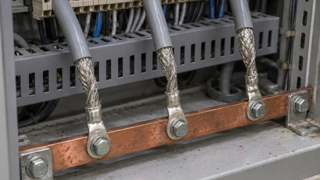
Instrument shields are usually grounded at one point on the receiving side, meaning the control panel or control room cabinet. The shield lands on the panel's ground terminal (FG or E terminal) or ground bar. Japanese manufacturer documents describe the same idea:
- Mitsubishi Electric: the installation manual for the FX3U-4DA analog output block says to ground the shield at one point on the signal receiving side, and not to share a common ground with power circuits. Because this block is an output, the receiving side is the device it sends the signal to
- JMACS (cable maker): for analog input signals, ground the shield on the computer side, where the current signal is converted to a voltage
- Yokogawa: for FOUNDATION Fieldbus wiring, ground the shield at one point only, usually at the host or power-supply end
At the field transmitter, the shield is typically cut back and insulated so that it does not touch the transmitter case or the conduit. When the device manual specifies a different arrangement, the manual takes precedence.
The shield is grounded inside the panel. At the field end it is insulated and left floating.
If the cable passes through a junction box, the shield is carried through on a terminal, and the ground point stays at the panel end only.
For how junction boxes appear on Japanese drawings, see Junction Box (JB) on Japanese Drawings. Field wiring versus panel wiring is covered in Naisen vs Gaisen.
Ungrounded Shields Do Almost Nothing
A shield that is grounded at neither end does very little shielding. The noise it picks up has nowhere to go, and the shield's potential is left undefined.
The Ibaraki Prefectural Industrial Technology Center in Japan compared radiated noise (30–700 MHz) from 0.6 m (2 ft) cables carrying an 8 MHz clock signal. An ungrounded two-core shielded cable performed almost the same as an unshielded twisted pair.
The report concludes that a shielded cable has no EMC suppression effect unless it is grounded, and in this test, grounding both ends (two-point grounding) worked best. The test used short cables on electronic equipment at high frequencies, but JMACS also states that, for instrumentation cables, leaving the shield ungrounded sharply reduces its effect.
With one-end grounding, the floating end has no path for lightning surges. In an example of signal lines fitted with surge protectors, M-System recommends covering the cut end with an insulator such as heat-shrink tubing to prevent sparking, or installing a separate surge protector for the shield. If your site is exposed to lightning, ask the supplier how the floating end is meant to be treated.
Whether one end or both are grounded, the shield must be grounded, and in general, the lower the ground resistance, the better the shielding.
Electromagnetic Shields: Ground Both Ends
Electromagnetic shields are grounded at both ends. This gives current a path through the shield, and that current cancels the effect of the magnetic field.
When an external magnetic field drives current through the shield, the current induces a voltage in the conductors that opposes the noise voltage. The two cancel, so less noise remains on the signal. The Ibaraki report explains the benefit of two-point grounding the same way.
Both-end grounding, however, forms a loop through the earth. JMACS states that the ground potential difference between the two ends must be eliminated so that no current flows through that loop. As with electrostatic shields, lower ground resistance gives better shielding.
For high-frequency noise in electronic equipment (EMC), grounding both ends is also the norm. Murata's noise suppression course says ordinary shielded cables are grounded at both ends, and that an electrostatic shield can sometimes be grounded at one end only.
In short, low-frequency instrument signals get one-end grounding, and high-frequency noise is handled with both-end grounding.
Typical Uses and Network Cable Rules
Everyday examples of shielded cable include shielded LAN cable (STP), TV antenna coaxial cable, and some phone charging cables. Many standard LAN cables are unshielded (UTP), so check the packaging or the cable marking.
In plants and factories, shielded cables typically carry:
- 4–20 mA instrument signals (transmitter to control panel or DCS)
- Thermocouple and RTD signals, which are small signals
- Pulse and analog input/output signals
- Field networks and other communication links
For signal names such as AI, AO, and PI, see DI/DO, AI/AO, PI/PO on Japanese I/O lists.
Related: Thermocouple vs RTD: JIS/IEC Classes on Japanese Equipment
Communication cables are different: each network standard has its own recommended shield grounding. Figure 5 combines the rules above with the network recommendations collected by M-System, a Japanese signal-conditioner maker. Check the device manual and the network's installation guide first, and use the signal type and the purpose of the shield only when neither says anything.
Low-frequency instrument signals: one end. Magnetic or high-frequency noise: both ends.
Sources: JMACS technical data; Murata, "Basics of Noise Countermeasures"; M-System, "Instrumentation Tips." M-System notes that its network article is an edited version of a January 2012 piece and that standards may have changed since, so confirm against the current installation guide for each network.
How to Read Shield Notes on a Japanese Drawing
The fictional notes below show the kind of wording you may see and what each one usually means. Treat the interpretation as a starting point, and confirm it with the supplier.
| Note on the drawing (fictional example) | What it usually means | What to confirm |
|---|---|---|
| シールド線使用 (use shielded cable) | The signal must use shielded cable. The cable type is often given in the cable schedule | Cable type (e.g., CVV-S, CVV-SB, or an instrumentation cable) and whether a local equivalent is acceptable |
| シールドは盤側にて片側接地 (shield grounded at one end, panel side) | Ground the shield at the panel only. The field end floats | Which terminal or ground bar in the panel, and how the field end is to be finished |
| シールドは信号受取り側で一点接地 (single-point ground on the receiving side) | Ground at the end that receives the signal. For an output module, that is the receiving device, not the PLC | Which device is the receiving side for each signal |
| 現場側 絶縁処理 (field end: insulate) | At the field device, the shield is cut back and insulated so it touches nothing | Whether the device manual requires a different treatment, and how lightning exposure is handled |
| 両端接地 (ground both ends) | Electromagnetic shield, high-frequency signal, or a network that specifies both ends | Ground potential difference between the two ends, and the network's installation guide |
| 強電系と共通接地しないこと (do not share a ground with power circuits) | The shield ground must not be tied into the power-circuit ground | Where the separate signal ground connects to the plant grounding system under your local code |
| 中継端子箱にてシールド中継 (shield carried through at the junction box) | The shield is connected through a terminal in the junction box, not grounded there | That the junction box adds no second ground point |
Some Japanese manuals also give a separation distance. The Mitsubishi FX3U-4DA manual, for example, asks for analog signal cables to be kept at least 100 mm (4 in) away from main-circuit and high-voltage wiring. Other devices may give different values, so read each manual.
Local Codes and the Device Manual Come First
A Japanese shield note describes noise control for signal cables. It does not replace the safety grounding of the equipment, and it does not override the electrical code where the equipment is installed.
- Safety (protective) grounding: set by the electrical code at the installation site, such as NEC Article 250 in the US or IEC 60364 and the national code elsewhere. A shield ground does not replace the equipment grounding conductor
- Network cabling: follow the network's own installation guide. IEC 61918 covers installation of industrial communication networks and includes a clause on earthing and bonding of shielded cabling
- Device-specific requirements: the manual of the transmitter, PLC module, or drive overrides general rules, including which end to ground
- Termination method: how the shield or drain wire is connected and insulated follows the cable and accessory makers' instructions and your site's standards. Panel work follows your site's lockout/tagout and voltage-verification procedures. Before disconnecting a signal cable on running equipment, check the effect of losing that signal with the operations team
Your electrical engineer of record, the equipment maker, and, where required, the local inspector decide how these fit together on your site.
Checklist: What to Ask the Japanese Supplier
Use these questions when a Japanese drawing or specification calls for shielded cable and the grounding is unclear.
- For each shielded cable, is the shield electrostatic or electromagnetic, and is it grounded at one end or both?
- For one-end grounding, which end is grounded, and to which terminal (FG, E, SG, or ground bar)?
- How should the floating end be finished, and is a shield surge protector needed in lightning-prone areas?
- For shields specified for one-end grounding, is the shield carried through each junction box on a terminal, without adding a second ground point?
- Is the lead from the shield to the ground terminal kept as short as practical? A long lead can itself pick up noise
- Which cable type is specified (CVV-S, CVV-SB, instrumentation cable), and is a local cable with a comparable shield (tape, braid, or foil with drain wire) acceptable?
- For network cables, which installation guide and version does the design follow?
- Is the signal ground kept separate from the power-circuit ground, and where does it connect to the plant grounding system?
- What separation from power cables does the device manual require? If signal and power cables must share a metal duct, is a grounded metal separator specified?
Sample Inquiry Email
Subject: Shield grounding for signal cables – Drawing [drawing number]
Dear [Name],
Thank you for the wiring diagrams for [equipment name]. Before we install the field cables, please confirm the shield grounding for the following signals: [tag numbers].
1. Is each shield grounded at one end or at both ends?
2. If one end, which end (panel or field) and which terminal?
3. How should the ungrounded end be finished?
4. Do you accept [local cable type] in place of CVV-S, provided it has a [copper tape / braid] shield?
5. Does the network cabling follow a specific installation guide? If so, please send the document name and version.
Our installation must also comply with [NEC / local code], so please let us know if your drawing assumes any Japanese site condition we should review.
Best regards,
[Your name]
Limits of This Guide
- The one-end and both-end rules here are rules of thumb from Japanese cable and instrument makers. Device manuals, network standards, and project specifications can differ, and they take precedence
- This guide covers shields on control and instrument signal cables. It does not cover medium- or high-voltage power cable shields, which are grounded for fault-current and shock protection under different rules
- Drawing wording varies by company. The notes in this guide are fictional examples
- This is not an installation procedure. Grounding and termination work follows your local electrical code, the manufacturers' instructions, and your site's procedures
FAQ
What happens if a cable shield is not grounded?
It provides almost no shielding. The noise it picks up has nowhere to drain, and in one Japanese public test an ungrounded shielded cable performed almost the same as an unshielded twisted pair. A floating end can also carry high voltage from lightning surges and spark over.
Should a cable shield be grounded at one end or both ends?
It depends on the purpose. Electrostatic shields on low-frequency instrument signals such as 4–20 mA are grounded at one end. Electromagnetic shields, high-frequency EMC applications, and networks whose standard calls for it are grounded at both ends. The device manual overrides both rules.
Which end of the shield should be grounded, the panel or the field?
Japanese practice for instrument signals is the receiving side, usually the control panel, and maker documents describe single-point grounding on the receiving side. Some devices specify grounding at the field end. In that case, follow the manual. Either way, the key is a single ground point.
What does CVVS (CVV-S) cable mean?
CVV is a Japanese control cable with vinyl insulation and a vinyl sheath, used for control circuits of 600 V or less. CVV-S adds a copper tape shield, and CVV-SB adds a copper wire braid shield. When sourcing locally, compare the shield construction and the voltage rating on the datasheet rather than the name.
What is the difference between the shield and the drain wire?
The shield is the layer that intercepts noise. The drain wire is a bare wire running along the shield. Aluminum foil shields are hard to connect to a terminal directly, so the drain wire is used for the ground connection.
Is this the same as grounding the shield of a medium-voltage power cable?
No. The shield of a high-voltage power cable is grounded mainly for protection against ground faults and electric shock, and the method is set by electrical codes and the cable maker. This guide covers signal cables in control and instrumentation. For leakage protection in low-voltage circuits on Japanese drawings, see NFB vs. MCCB vs. ELB.
Sources
- Shield types and grounding (electrostatic: single point; electromagnetic: both ends): JMACS, technical data "Noise Countermeasures for Cables" (Japanese)
- CVV, CVV-S, and CVV-SB: JMACS, CVV control cable product page (Japanese)
- Single-point grounding on the receiving side, no common ground with power circuits, 100 mm separation: Mitsubishi Electric, FX3U-4DA Installation Manual JY997D20801 (Japanese)
- Ground potential difference, one-end grounding, and the floating end: M-System, Instrumentation Tips "Shielded Wire and Surge Protectors" (Japanese)
- Shield grounding by network: M-System, Instrumentation Tips "Shield Wiring for Communication Cables" (Japanese)
- Both-end grounding and electrostatic shields: Murata Manufacturing, "Basics of Noise Countermeasures: Radiated Noise and Countermeasures 3" (Japanese)
- Effect of ungrounded shields: Ibaraki Prefectural Industrial Technology Center, Research Report No. 24, "Study on EMC Countermeasure Techniques I: Cables" (Japanese)
- Fieldbus shield grounded at one point: Yokogawa, "10 Steps to Better Foundation Fieldbus Installations"
- Instrumentation cable example: JMACS, KNPEV-SB specification (Japanese)
- Industrial network installation: IEC 61918, Industrial communication networks – Installation of communication networks in industrial premises (preview)
Original article in JapaneseThis guide is adapted from a MONOSCOPE article written for readers in Japan: シールドケーブルの種類と正しい接地方法|片側接地・両端接地の使い分け
About the editor
 MONOSCOPE EditorFOUNDER & EDITOR
Spent about ten years at a plant equipment maker and a plant engineering company, proposing, designing, and commissioning equipment, then moved into web marketing. Now a web consultant for B2B manufacturers, helping them explain their products and technology. Licensed in Japan as an Energy Manager and a Third-Class Chief Electrical Engineer.
Has run an engineering blog since 2017 (500+ articles) and a Japanese YouTube channel with about 20,000 subscribers. Each English guide is written from the Japanese shop-floor point of view and checked against the cited standards.