JIS Surface Roughness: Ra, Rz, and Triangle Finish Symbols
A drawing arrives from a Japanese customer or supplier. One face is marked Ra 1.6, a sealing face says Rz 6.3, and an older sheet in the same package has ▽▽▽ next to a bore and "6.3S" on a flange. All four are surface roughness callouts (表面粗さ, hyomen arasa), but they reflect different editions of JIS (Japanese Industrial Standards), and some are older notations that the current standard no longer uses.
Reading them correctly matters because the same symbol can mean different things. Ra and Rz measure different features of a surface, so on the same surface the Rz value is several times the Ra value. And "Rz" itself changed meaning in the 2001 edition of JIS B 0601. If the machine shop and the inspector read an old drawing differently, parts can be made to one number and rejected against another.
This guide explains what Ra and Rz measure, how to read old Rz, Rmax, and triangle (▽) marks, how JIS relates to ISO 4287, ISO 21920, and ASME B46.1, and what roughness common machining processes reach. It ends with a quick-reference table, a checklist of what to confirm with the Japanese side, and an FAQ. The status of each standard was checked as of October 1, 2026.
Contents
- Quick Reference: Roughness Callouts on Japanese Drawings
- Ra vs. Rz: What Each Number Measures
- JIS B 0601 Ra and Rz: Old Rz vs. New Rz
- Which Standards Apply Today: JIS, ISO 4287, and ISO 21920
- How to Read JIS Surface Finish Symbols
- Triangle Surface Finish Symbols (▽▽▽) on Japanese Drawings
- Typical Ra by Machining Process
- How Surface Roughness Is Measured
- Is a Finer Roughness Callout Always Better?
- Checklist: What to Confirm With the Japanese Side
- Limits of This Guide
- Summary
- FAQ
- Sources
Quick Reference: Roughness Callouts on Japanese Drawings
Use this table to identify what you are looking at, then read the matching section below for details.
| What you see | What it usually means | Where it comes from | What to do |
|---|---|---|---|
| Ra 1.6 | Arithmetical mean roughness, upper limit 1.6 µm (about 63 µin) | Current JIS B 0031 / B 0601 (Ra defined as in ISO 4287) | Measure Ra as specified |
| Rz 6.3 on a drawing that applies JIS B 0601:2001 or later | Maximum height of the profile, upper limit 6.3 µm | JIS B 0601:2001 and later (matches ISO 4287 Rz) | Measure Rz (maximum height) |
| Rz on a drawing that applies JIS B 0601:1994 or earlier | Possibly ten-point mean roughness (now called RzJIS) | JIS B 0601:1994 and earlier | Check the drawing date and standard; confirm in writing |
| Ry, Rmax, or a value with "S" (e.g., 6.3S) | Maximum height (today's Rz) | JIS B 0601:1994 (Ry), 1982 (Rmax) | Treat as maximum height; confirm the edition |
| Value with "a" (e.g., 1.6a) | Arithmetical mean roughness (Ra) | Older JIS notation | Read as Ra |
| Value with "Z" (e.g., 6.3Z) | Ten-point mean roughness (old Rz, now RzJIS) | Older JIS notation | Agree on RzJIS or a replacement value |
| ▽▽▽▽ / ▽▽▽ / ▽▽ / ▽ | Old finish marks; more triangles mean a smoother surface | Older JIS notation; ranges from the 1994 editions' reference tables | Use the Ra ranges in Figure 6 only as a guide; agree on an Ra value |
| ~ (wavy line) | Surface left unmachined (as cast, as forged) | Old finish marks | Confirm whether any limit applies |
Ra vs. Rz: What Each Number Measures
In short, Ra is the average of the peaks and valleys across the whole profile, while Rz is the distance from the highest peak to the deepest valley. JIS calls Ra the arithmetical mean roughness and Rz the maximum height roughness. Both are given in micrometers (µm).
Magnify a machined surface and you see a series of small peaks and valleys. Take a cross-section of that surface, remove the longer-wavelength waviness, and you get the roughness profile. Both Ra and Rz are calculated from a fixed stretch of this profile called the sampling length.
Ra averages the deviation from the mean line. Rz is the gap between the highest peak and the deepest valley.
This schematic illustrates the concept and is not a measured profile. Definitions follow JIS B 0601:2013.
Ra is the mean of the absolute distances between the profile and the mean line. Because it averages the whole profile, a single scratch barely moves the number. That stability is why Ra is widely used to specify the roughness of a part as a whole.
Rz adds the height of the highest peak to the depth of the deepest valley within the sampling length. One protruding peak or deep scratch shows up strongly in the result. Designers often specify Rz on sealing faces and sliding surfaces (surfaces that rub against a mating part), where a small local defect can cause leaks or wear.
They look at different features, so their values do not match even on the same surface.
Definitions per JIS B 0601:2013. Typical uses are summarized from machining suppliers' technical references.
JIS B 0601 Ra and Rz: Old Rz vs. New Rz
An Rz on an older Japanese drawing may not mean what Rz means today. Up to the 1994 edition of JIS B 0601, Rz meant ten-point mean roughness (十点平均粗さ, juten heikin arasa). From the 2001 edition on, Rz means maximum height roughness. The symbol is the same, but the calculation is different.
Ten-point mean roughness is the average height of the five highest peaks plus the average depth of the five deepest valleys. Because it averages five points on each side, it tends to give a smaller number than today's Rz, which depends only on the single highest peak and deepest valley.
The symbol for maximum height also moved: Rmax in the 1982 edition, Ry in the 1994 edition, and Rz from 2001. Ten-point mean roughness was dropped from the international standard, ISO 4287:1997. Because Japanese industry had used it so widely, JIS kept it for reference in an annex under the symbol RzJIS.
Rz changed meaning in the 2001 edition.
Based on the main text and Annexes JA and JB of JIS B 0601:2013 and technical references from Mitutoyo and Keyence.
JIS B 0031:2003, the standard for indicating surface texture on drawings, states in effect that a callout made under an older standard is interpreted according to the rules in force at that time. In other words, whether an Rz on a drawing means maximum height or ten-point mean depends on when the drawing was made and which standard it applied.
Older drawings may also put a letter after the number, as in "1.6a," "6.3S," or "6.3Z." In makers' reference tables taken from the old standard, "a" stands for arithmetical mean roughness, "S" (or "s") for maximum height, and "Z" (or "z") for ten-point mean roughness.
When you reuse an old drawing or receive one in the old notation, check the title block and notes for the applicable standard. If it is still unclear, agree with the Japanese side on how to read it before work starts. For example, rewrite a ten-point mean requirement as RzJIS so that the purchaser and the machine shop are reading the same value.
Which Standards Apply Today: JIS, ISO 4287, and ISO 21920
According to the Japanese Standards Association (JSA) catalog, as of October 1, 2026, JIS B 0601:2013 defines the parameters and JIS B 0031:2003 defines the drawing indication. Neither has been withdrawn or replaced.
JIS B 0031 received Amendment 1 in March 2022. That amendment followed the replacement of a filter standard that JIS B 0031 cites. It did not change the drawing symbols.
Definitions, drawing indication, and measurement are covered by separate standards.
JIS status taken from the JSA Webdesk catalog on October 1, 2026.
On the international side, ISO published the ISO 21920 series in December 2021, replacing ISO 4287, ISO 4288, ISO 1302, and other standards. The ISO editions that the current JIS standards correspond to have therefore been superseded.
When we checked, the JSA catalog listed no JIS standard corresponding to ISO 21920, although JSA does sell Japanese translations of it.
To keep things clear, read Japanese drawings by JIS B 0601:2013 and JIS B 0031:2003, and treat a drawing that cites ISO 21920 as a different standard. ISO 21920 changes how some parameters are calculated, and technical commentaries note that the same surface can give different values.
JIS is starting to catch up, though. JSA's list of planned JIS revisions (as of September 11, 2026) includes aligning JIS B 0031 with ISO 21920-1 and JIS B 0633 with ISO 21920-3, with drafting scheduled to begin in July 2026.
No revision date has been announced, so cite standards with their year of issue on drawings and in internal specifications. Also note that the JIS B 0681 series covers areal (3D) roughness. It runs in parallel with profile parameters such as Ra and Rz rather than replacing them.
Where ASME B46.1 Fits
In the US, surface texture is covered by ASME B46.1, Surface Texture (Surface Roughness, Waviness, and Lay), and drawings often give Ra in microinches (µin). The unit conversion is exact: 1 µin = 0.0254 µm, so 1 µm ≈ 39.37 µin. In practice, charts pair the JIS/ISO preferred values with rounded microinch values, such as 0.8 µm = 32 µin and 1.6 µm = 63 µin.
Some US flange and piping documents use the term AARH (arithmetic average roughness height) for the same averaged roughness that Ra describes. This guide maps only the units. It does not compare ASME and JIS definitions of other parameters, cutoffs, or acceptance rules, so confirm those separately when a part must satisfy both.
| Ra (µm, JIS/ISO) | Ra (µin, conventional) | Exact conversion (µin) |
|---|---|---|
| 0.025 | 1 | 0.98 |
| 0.05 | 2 | 1.97 |
| 0.1 | 4 | 3.94 |
| 0.2 | 8 | 7.87 |
| 0.4 | 16 | 15.7 |
| 0.8 | 32 | 31.5 |
| 1.6 | 63 | 63.0 |
| 3.2 | 125 | 126 |
| 6.3 | 250 | 248 |
| 12.5 | 500 | 492 |
| 25 | 1000 | 984 |
| 50 | 2000 | 1969 |
How to Read JIS Surface Finish Symbols
Read the shape of the check-mark symbol to see whether material removal is allowed, then read the parameter and value next to it to see the requirement. JIS groups roughness, waviness, flaws, and similar features under the term surface texture (表面性状, hyomen seijo), and it defines three basic symbols.
The symbol shape shows whether material removal is required. Positions a–e hold the requirements.
Schematic based on JIS B 0031:2003. Proportions do not match the figures in the standard.
The basic symbol applies when it does not matter whether material is removed (by cutting, grinding, or similar processes). Adding a bar to close the symbol into a triangle means "material removal required." Adding a circle means "material removal not allowed," so the surface stays as cast or as supplied.
To state a requirement, the drawing extends the long leg of the symbol with a horizontal line and writes the parameter and value below it, as in "Ra 1.6." The value is an upper limit, and the unit (µm) is left off. To specify the manufacturing method or the lay direction, the drawing adds them at positions c and d in Figure 5.
Lay is the direction of the tool or wheel marks. JIS provides symbols for lay parallel to the projection plane, perpendicular, crossed, multidirectional, circular, radial, and nondirectional.
Related: How to Read Japanese Engineering Drawings (JIS B 0001)
How "max" Changes the Acceptance Rule
With no suffix, the 16% rule applies. The part passes if no more than 16% of the values measured on all the sampling lengths in one evaluation length exceed the specified value.
Add "max," as in "Rzmax 6.3," and the max rule applies: no measured value anywhere on the surface may exceed the limit. That is a much stricter requirement. When both upper and lower limits are given, they are marked U and L.
One of the main changes in the planned revision of JIS B 0031 is to follow ISO 21920-1 by dropping the 16% rule and keeping only the max rule. Drawings made under the current JIS B 0031:2003 still default to the 16% rule.
Related: Datum Selection in GD&T: JIS vs ASME on Japanese Drawings
Triangle Surface Finish Symbols (▽▽▽) on Japanese Drawings
As a guide, ▽▽▽ corresponds to Ra 0.4–1.6, ▽▽ to Ra 3.2–6.3, and ▽ to Ra 12.5–25 (µm). The triangles are an older notation called finish marks (仕上げ記号, shiage kigo). The more triangles, the smoother the surface.
Convenience correspondence from the reference tables in older JIS editions.
From MISUMI and Linex excerpts of the reference tables in JIS B 0601:1994 and JIS B 0031:1994. Units: µm. Approximate µin values were added by MONOSCOPE (1 µm ≈ 39.37 µin). Old Ry corresponds to today's Rz; old Rz corresponds to today's RzJIS. The reference table notes that the correspondence is for convenience and is not exact.
Treat these ranges as a starting point for discussion, not a conversion. When a drawing still carries triangle marks, ask the Japanese side to confirm a single Ra (or Rz) value for each surface and to update the drawing or add a note.
Can You Convert Ra to Rz?
There is no exact conversion formula. Ra is an average and Rz is a peak-to-valley value, so the ratio between them depends on the shape of the surface. A uniform surface with few scratches gives a small ratio; a surface with scattered deep scratches gives a large one. The reference notes to the indication examples in JIS B 0031:2003 also state that Rz is often well above three times Ra.
The common rule of thumb that "Rz is about four times Ra" comes from the way the reference table in Figure 6 is laid out. The preferred number series pairs Ra 1.6 with 6.3 and Ra 3.2 with 12.5, a factor of four. That pairing helps designers choose drawing values. It is not a formula for converting one measured value into the other.
So you cannot measure Rz on a surface specified in Ra, divide by four, and call it a pass. Measure the parameter the drawing specifies: Ra if it says Ra, Rz if it says Rz.
Typical Ra by Machining Process

As a rough guide, turning and milling reach about Ra 1.6, grinding Ra 0.2–1.6, and lapping or superfinishing Ra 0.2 or finer. These numbers shift a great deal with the tool, feed, material, and machine condition.
MISUMI's technical data includes a table of roughness ranges by process. Even within turning, the range runs from Ra 0.1–0.4 for carefully controlled precision work to Ra 12.5 or more for roughing. The process name alone does not set the roughness.
Smoother to the left. The dark segment is the range listed as "precision"; the light segment is the rest of the range.
Plotted on a log scale from the "roughness ranges by machining method" table in MISUMI's technical data (Ra, µm). These are not JIS limits; actual values depend on tool, feed, material, and other conditions. The table has no "precision" range for EDM.
Sanwa Needle Bearing, a Japanese precision machining company, also gives Ra 1.6–0.8 as a typical range for turning. It notes that holding Ra 0.4 or finer consistently usually requires adding grinding. The company publishes guide values by process for precision work, and they broadly match the dark segments in Figure 7.
The old finish-mark grades in Figure 6 are another clue to the process. Sado Seimitsu, a precision parts maker, describes those grades as guide values only. It adds that advances in machine tools and cutting tools now let cutting reach Ra 1.6 or finer, and turning about Ra 0.8.
The last operation does not decide roughness on its own. A part that needs hardness is typically machined to shape, quenched and tempered, and then ground to remove heat-treatment distortion and reach the final finish.
A callout of Ra 0.4 or finer is hard to hold by cutting alone, so it often adds a grinding or polishing step. Knowing how cutting, grinding, and casting differ helps you predict how a roughness callout will affect the process plan.
Related: Quenching, Tempering, Annealing, Normalizing on JIS Drawings
How Surface Roughness Is Measured

The standard tool is a stylus profilometer. A diamond stylus with a rounded tip traces the surface, and the instrument records its vertical movement as a profile. JIS B 0651 specifies a conical stylus with a spherical tip and lists tip radii of 2 µm, 5 µm, and 10 µm.
Measuring direction matters too. Under JIS B 0633, if the drawing does not specify a direction, you measure in the direction that gives the largest Ra or Rz, which is perpendicular to the lay. Tracing along the tool marks gives a value lower than the true roughness.
Sampling Length and Evaluation Length
To separate roughness from the rest of the profile, you need to decide which wavelengths count as roughness. That boundary is the cutoff value λc (lambda c), and it equals the sampling length.
The standard evaluation length is five sampling lengths. JIS B 0633 selects them by roughness level as follows:
- Ra over 0.02 up to 0.1: sampling length 0.25 mm, evaluation length 1.25 mm
- Ra over 0.1 up to 2: sampling length 0.8 mm, evaluation length 4 mm
- Ra over 2 up to 10: sampling length 2.5 mm, evaluation length 12.5 mm
- Rz over 0.5 up to 10: sampling length 0.8 mm, evaluation length 4 mm
- Rz over 10 up to 50: sampling length 2.5 mm, evaluation length 12.5 mm
These ranges apply to non-periodic profiles, where peaks and valleys are irregular, as on ground surfaces. For periodic profiles, as on turned surfaces, the sampling length is chosen from the mean spacing of the profile elements (RSm).
Most finished surfaces on ordinary machine parts fall in the 0.8 mm sampling length, 4 mm evaluation length range (about 0.03 in and 0.16 in). Changing the cutoff changes the result on the same surface, so record the measurement conditions with the results whenever you compare measurements.
The instrument itself must be reliable. Check it with surface roughness reference specimens and manage its calibration and traceability the same way you manage dimensional gauges.
Related: JCSS Calibration: Certificates, Intervals, and Records
Profile Roughness vs. Areal Roughness
Ra and Rz are profile parameters, measured along a single line. Areal roughness instead captures the height of a whole area, using a laser microscope, white-light interferometer, or similar instrument, and evaluates it as a surface. Non-contact methods have the advantage of not marking the part.
Areal parameters start with S and are defined in JIS B 0681-2 (corresponding to ISO 25178-2). Sa extends Ra to an area (arithmetical mean height), and Sz extends Rz (maximum height). Areal evaluation is less affected by the variation in results from measurement location and trace direction that profile methods face.
That said, Sa does not necessarily equal Ra, and Sz does not necessarily equal Rz, because the measured area and the filtering differ.
If a drawing specifies Ra, evaluate it as profile roughness. Indicating areal requirements on drawings is covered by a separate standard, JIS B 0681-1:2023.
Is a Finer Roughness Callout Always Better?
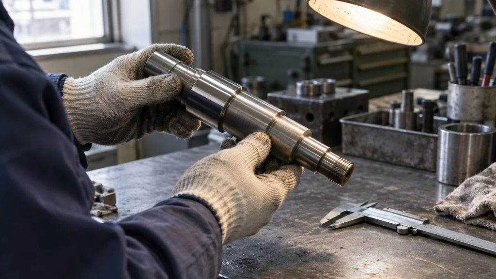
No. Set roughness by balancing what the surface has to do against what it costs to make. A value finer than the function needs adds operations, lead time, and cost, and may not improve the product at all.
The roughness a surface needs depends on its job.
Fatigue strength based on Kobelco Research Institute technical material; sliding and sealing based on Sado Seimitsu and NOK references.
Real design standards show how values vary by application. NOK's O-ring catalog (based on JIS B 2401-2:2012) sets the roughness of the contact surfaces an O-ring seals against, by application.
For static seals without pressure pulsation, it gives Ra 1.6 / Rz 6.3; with pulsation, Ra 0.8 / Rz 3.2; and for dynamic seals, Ra 0.4 / Rz 1.6. The installation chamfer is Ra 3.2 / Rz 12.5, and the groove side and bottom have their own values for each application.
Even around a single O-ring groove, then, moving surfaces get fine values, and surfaces the seal only passes over during assembly can be rougher. The catalog explains that groove roughness affects friction and wear in dynamic use, and in static use, whether the rubber conforms to the mating surface well enough to seal reliably.
Example: Assigning Roughness Surface by Surface (Fictional)
This is a fictional example to show the reasoning. Suppose a stepped shaft, similar to a motor output shaft, is made by turning. Calling out "Ra 0.4" on every surface would mean grinding every diameter, adding operations and cost.
Sort the surfaces by function instead. The surface under the oil seal lip handles both sliding and sealing, so it needs a fine finish. The bearing seat needs a stable fit. The remaining diameters and end faces touch no mating part, so they can stay as turned.
For example, Ra 0.4 on the seal surface, Ra 0.8 on the bearing seat, and Ra 3.2–6.3 elsewhere means grinding only the two surfaces that need it. These numbers are for illustration only. In practice, follow the values recommended by the seal and bearing manufacturers.
Watch the downstream processes, too. With some types of plating, the substrate texture shows through the coating, so decide whether the drawing value applies before or after treatment. JIS B 0031 includes indication examples that separate requirements before and after surface treatment.
Related: JIS Plating Callouts (Ep-Fe/Zn8/CM2) and ASTM Equivalents
Surfaces with tight dimensional tolerances, such as fits, also need a correspondingly fine roughness. MISUMI explains that on a rough surface, friction wears down the peaks quickly and the dimension drifts from the design value. In practice, decide tolerance and roughness together, starting from what the surface has to do.
Checklist: What to Confirm With the Japanese Side
Before you machine or inspect a part from a Japanese drawing, confirm these points in writing with the Japanese customer, designer, or supplier.
- Which edition applies? Check the title block (表題欄, hyodai-ran) and notes for the drawing date and the cited standard, such as JIS B 0601:2013 or JIS B 0601:1994.
- What does each Rz mean? On drawings made before 2001, ask whether Rz means maximum height (today's Rz) or ten-point mean roughness (RzJIS).
- What replaces triangle marks? For ▽, ▽▽, ▽▽▽, or ▽▽▽▽, ask for a single Ra or Rz value per surface instead of working from the guide ranges.
- What do suffix letters mean? Confirm "a," "S," and "Z" readings (Ra, maximum height, ten-point mean) if they appear.
- Which acceptance rule applies? The 16% rule (no suffix) or the max rule ("max")? Are there U/L upper and lower limits?
- Which unit and value govern? If your system uses µin, agree whether the µm value or the rounded µin value is the contractual limit.
- What measurement conditions apply? Cutoff (sampling length), evaluation length, stylus tip radius, and measuring direction, especially when your lab and the Japanese lab must agree.
- Before or after surface treatment? For plated or coated surfaces, which state does the roughness value apply to?
- Is ISO 21920 or ASME B46.1 involved? If your drawing or contract cites a different standard, confirm which one governs.
- Are any values finer than the function needs? If a callout forces extra grinding, ask whether a coarser value is acceptable on surfaces with no functional role.
Limits of This Guide
- The triangle-mark and Ra/Rz correspondences come from reference tables that themselves say the relationship is for convenience and not exact. They are not acceptance criteria.
- Microinch values are conversions and conventional rounded pairs. This guide does not compare ASME B46.1 parameter definitions, filters, or acceptance rules with JIS.
- Roughness by process varies with tool, feed, material, and machine. The ranges shown are published guide values, not capabilities of any specific shop.
- Standard status was checked as of October 1, 2026. JIS B 0031 and JIS B 0633 are scheduled for revision, and the rules may change. Check current editions before you rely on them.
- Company and industry practice varies. Where a customer specification, industry standard, or seal or bearing maker's recommendation applies, it takes priority over the general guidance here.
Summary
- Ra is the average deviation of the profile; Rz is the highest peak plus the deepest valley. On the same surface, Rz is several times larger.
- In JIS up to 1994, Rz meant ten-point mean roughness; from 2001, it means maximum height. On old drawings, check the applicable standard.
- As of October 1, 2026, JIS B 0601:2013 and JIS B 0031:2003 are current. ISO has moved to ISO 21920, and work to align JIS B 0031 and related standards has started.
- Triangle marks to Ra, and Ra to Rz, are guide correspondences from old JIS reference tables. There is no exact conversion formula.
- Ra converts to microinches at 1 µm ≈ 39.37 µin (for example, 1.6 µm ≈ 63 µin).
- Finer is not always better. Set roughness surface by surface, based on sliding, sealing, fatigue, appearance, and cost.
Surface roughness is the number that connects three roles: the designer writes it on the drawing, the machinist produces it, and the inspector measures it. When an old symbol is unclear, start by checking the applicable standard and the date of the drawing, and agree on one reading with the Japanese side.
FAQ
What does ▽▽▽ mean on a Japanese drawing?
It is an old JIS finish mark for a fine machined finish. Reference tables pair it with roughly Ra 0.4–1.6 µm (about 16–63 µin). The correspondence is not exact, so ask the Japanese side to confirm an Ra value.
Is JIS Rz the same as ISO Rz?
From the 2001 edition of JIS B 0601, Rz means maximum height, corresponding to Rz in ISO 4287:1997. Before 2001, JIS Rz meant ten-point mean roughness, which current JIS calls RzJIS. ISO 21920 changes some calculations, so check which ISO standard a drawing cites before you treat values as equivalent.
What is RzJIS?
RzJIS is ten-point mean roughness: the average of the five highest peaks plus the average of the five deepest valleys. It is the old JIS Rz, kept in an annex of JIS B 0601 for reference.
How do I convert Ra 1.6 to microinches?
Multiply by 39.37: Ra 1.6 µm is about 63 µin. Charts commonly pair 0.8 µm with 32 µin and 3.2 µm with 125 µin.
Can I convert Ra to Rz with a factor?
No. The ratio depends on the surface. The "Rz ≈ 4 × Ra" rule comes from how preferred values are paired in reference tables, not from measurement. Measure the parameter the drawing specifies.
Sources
- Parameter definitions and current status: Japanese Standards Association (JSA) Webdesk, JIS B 0601:2013 (Japanese) (accessed October 1, 2026)
- Drawing indication and amendment: JSA Webdesk, JIS B 0031:2003 (Japanese), JSA, list of JIS drafts under revision, as of June 7, 2022 (Japanese)
- Planned revisions of JIS B 0031 and JIS B 0633: JSA, list of JIS drafts under revision, as of September 11, 2026 (Japanese)
- Drawing-related JIS and Japanese translations of ISO 21920: JSA Webdesk, drawing JIS list (Japanese)
- Assessment, instruments, and areal standards: JIS B 0633:2001, JIS B 0651:2001, JIS B 0681-2:2018, JIS B 0681-1:2023 (JSA Webdesk, Japanese)
- Old vs. new symbols: Mitutoyo, on the 2001 JIS for surface roughness (Japanese), Keyence, differences between JIS B 0601-1994 and JIS B 0601-2001 (Japanese), MISUMI, surface texture: profile method, including JIS B 0601:2013 excerpts (Japanese), Mitsubishi Materials, surface roughness (Ra, Rz, RzJIS)
- Old finish marks vs. Ra: MISUMI, surface roughness excerpts from JIS B 0601:1994 and JIS B 0031:1994 (Japanese), Linex, JIS excerpts: surface roughness (Japanese)
- Symbols, 16% rule, and max rule: MISUMI, indication of surface texture, excerpts from JIS B 0031:2003 (Japanese)
- ISO 21920 and the standards it replaced: ISO 21920-2:2021, Digital Surf, "What are the differences between ISO 4287 and ISO 21920?", PTB, roughness measurement standards
- ASME B46.1 and µm–µin conversion: ASME, B46.1 Surface Texture (Surface Roughness, Waviness, and Lay), Wevolver, surface finish chart: Ra, Rq, and N grade conversions, Project Materials, Ra vs. AARH
- Roughness by machining process: MISUMI meviy, surface roughness, roughness ranges by machining method (Japanese), Sanwa Needle Bearing, surface roughness in turning (Japanese), Sado Seimitsu, surface roughness explained (Japanese)
- Sampling length, evaluation length, and stylus characteristics: Mitutoyo, surface roughness basics (Japanese)
- Instruments and areal roughness: Keyence, principles of common measuring instruments (Japanese), Keyence, areal roughness (ISO 25178) (Japanese), Keyence, Sa arithmetical mean height (Japanese)
- Tolerance, roughness, and fatigue strength: MISUMI meviy, surface roughness symbols Ra and Rz (Japanese), Kobelco Research Institute, Kobelnics No. 57, fatigue basics for fatigue design (Japanese)
- O-ring groove roughness: NOK, O-ring catalog (Cat. No. 051), Section 7, design criteria, Table 5-2 (Japanese)
Original article in JapaneseThis guide is adapted from a MONOSCOPE article written for readers in Japan: 表面粗さRaとRzの違いは?図面の記号と加工別の目安をQ&Aで整理
About the editor
 MONOSCOPE EditorFOUNDER & EDITOR
Spent about ten years at a plant equipment maker and a plant engineering company, proposing, designing, and commissioning equipment, then moved into web marketing. Now a web consultant for B2B manufacturers, helping them explain their products and technology. Licensed in Japan as an Energy Manager and a Third-Class Chief Electrical Engineer.
Has run an engineering blog since 2017 (500+ articles) and a Japanese YouTube channel with about 20,000 subscribers. Each English guide is written from the Japanese shop-floor point of view and checked against the cited standards.