Circuit Protector (CP) vs. Circuit Breaker (NFB) and Fuse
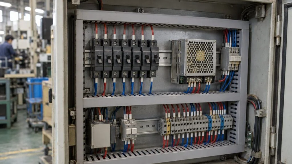
Imagine a machine shipped from Japan. On the control panel drawing, the 24 V DC outputs feed a row of small devices marked "CP," each with a rating such as "2P 3A." The parts list calls them サーキットプロテクタ (circuit protector). One of them trips every time the machine starts, and someone on your team suggests swapping it for a local miniature circuit breaker of the same amps, or for the next size up.
A circuit protector (CP) protects equipment and control circuits from overcurrent. A breaker labeled NFB or MCCB protects the wiring. They are built to different standards and do different jobs, so a matching current rating does not make one a drop-in replacement for the other, or for a fuse.
This guide explains what a CP is, how it trips, how to read P/E notation and model codes, how it differs from an NFB, a fuse, and an ELB, what to check when you select or replace one, and why resetting a CP is not the same as restarting the machine. It ends with a checklist, questions for the Japanese supplier, and a sample inquiry email.
Contents
- Key Points
- Quick Reference: Protective Devices on Japanese Drawings
- What Is a Circuit Protector (CP)?
- How a Circuit Protector Trips
- Reading CP Notation: Poles, Elements, and Model Codes
- Circuit Protector vs. Circuit Breaker (NFB/MCCB)
- Circuit Protector vs. Fuse
- Circuit Protector vs. ELB (Earth Leakage Breaker)
- Selecting or Replacing a Circuit Protector
- After a Trip: Resetting the CP vs. Restarting the Machine
- Checklist Before Replacing or Re-Rating a CP
- Questions for the Japanese Supplier
- Limits of This Guide
- FAQ
- Sources
Key Points
- CP = circuit protector, formally 機器保護用遮断器 (kiki hogo-yo shadanki, "breaker for equipment protection"). The Japanese standard is JIS C 4610, based on IEC 60934, Circuit-breakers for equipment (CBE)
- A CP protects devices and control circuits inside equipment. An NFB/MCCB protects wiring. A CP does not replace upstream wiring protection
- "2P1E" means two poles and one overcurrent trip element, not two power sources
- Selecting a CP takes more than the amp rating: check AC or DC, voltage, inrush current and its duration, breaking capacity at your voltage, the DC power supply's current limit, panel temperature, and auxiliary contacts
- "Auto reset" on a CP does not necessarily mean the circuit switches itself back on, and when the machine may restart is a separate decision, based on the machine's risk
- If a CP keeps tripping, find the cause before you consider a larger rating
Quick Reference: Protective Devices on Japanese Drawings
Use this table to match the label on a Japanese drawing or parts list with the device it refers to. The last column gives the closest international or North American category. It does not mean the products are interchangeable.
| Label you may see | What it is | Main job | Japanese standard | Closest category outside Japan |
|---|---|---|---|---|
| CP, CBE, サーキットプロテクタ (circuit protector), 機器保護用遮断器 (kiki hogo-yo shadanki) | Circuit protector / circuit-breaker for equipment | Overcurrent protection of devices and control circuits inside equipment | JIS C 4610 (mechanical types) | CBE (IEC 60934). In North America, CPs are often certified as UL 1077 supplementary protectors |
| NFB, MCCB, 配線用遮断器 (haisen-yo shadanki) | Molded case circuit breaker | Overload and short-circuit protection of wiring | JIS C 8201-2-1 | MCCB (IEC 60947-2). In the US, branch-circuit breakers are UL 489 |
| F, FUSE, ヒューズ (fuse) | Fuse | Opens on overcurrent by melting; must be replaced | Depends on fuse type | Fuse of the type and rating the equipment maker specifies |
| ELB, ELCB, 漏電遮断器 (roden shadanki) | Earth leakage circuit breaker | Leakage (ground-fault) protection; many models also cover overcurrent | JIS C 8201-2-2 and others | Residual current device (RCD) |
For NFB, MCCB, ELB, and the AF/AT ratings printed on Japanese breakers, see NFB vs. MCCB vs. ELB: Japanese circuit breaker terms.
What Is a Circuit Protector (CP)?
A circuit protector cuts power to a control circuit or load when overcurrent flows through it. Its formal Japanese name, kiki hogo-yo shadanki, translates as "breaker for equipment protection," and drawings and catalogs abbreviate it as CP or CBE.
In a control panel, CPs typically sit on the branches that feed sensors, indicators, solenoid valves, and similar devices, one CP per circuit. That makes faults easier to locate and, when the protection is properly coordinated, keeps a fault from stopping more of the machine than necessary.
The upstream breaker (NFB/MCCB) is a different device with a different job: it protects the feeder and branch wiring from overload and short circuits. Adding CPs downstream does not mean you can leave out wiring protection upstream. Decide which device protects which part of the circuit.
The upstream breaker, the power supply, and the branch CPs do not play the same role.
← Scroll sideways to see the full figure →
Concept sketch of the power path and device locations. Poles on the AC side, grounding, wire numbers, and terminal details are omitted. This is not a wiring diagram for building a panel.
CPs are used in machine tool control circuits, electronic equipment power supplies, and office equipment, and some products are made for medical equipment and vehicles. They come in mechanical and electronic types. Two devices both called "CP" can differ in internal design, supply type, and the standard they meet, so treat them as different products.
JIS C 4610:2005 is titled 機器保護用遮断器 and covers mechanical switching devices that protect circuits inside electrical equipment. Its preface names IEC 60934:2000, Circuit-breakers for equipment (CBE), as the basis for the revision. IEC 60934 itself was revised in 2019. Do not assume JIS C 4610 applies to electronic CPs; read the standards listed for the specific product.
Some series offer very small current ratings in fine steps, but the range differs from series to series. Mitsubishi Electric's CP30-BA, for example, is listed from 0.1 A to 30 A. That is one series, not a range that applies to every CP.
Voltage and current differ between the primary and secondary sides of a power supply, even for the same load. Check on the drawing which side each CP is on and what fault it is there to detect. Wire numbers and terminal numbers, not just device names, help you trace what each CP feeds downstream.
Related: Naisen vs Gaisen: Panel Internal Wiring vs Field Wiring
Related: Japanese Machine Control Panels: UL 508A, NFPA 79, and CE
How a Circuit Protector Trips
A CP combines a part that senses abnormal current with a part that opens the circuit. Sensing methods include thermal, magnetic, hydraulic-magnetic, and thermal-magnetic. Electronic CPs monitor current with an electronic circuit.
In a thermal CP, heat from the current reaches a bimetal strip, and the strip's movement opens the contacts. A bimetal is two metals with different thermal expansion rates bonded together, so it bends as it heats up.
How long a thermal CP takes to trip depends not only on the size of the current but also on how long it flows and on the ambient temperature. A CP is not a switch that opens the instant the current exceeds its rating, and expecting it to behave that way leads to wrong conclusions.
It helps to separate two steps: the sensing element heating up, and the contacts opening.
← Scroll sideways to see the full figure →
A concept drawing of a thermal mechanism, not the internal design of any specific product. Magnetic and electronic CPs may not use a bimetal at all.
A magnetic CP uses the magnetic force produced by the current to move an armature and release the trip mechanism. Some hydraulic-magnetic types slow that movement with an oil dashpot to get the time delay they need.
Magnetic types still need their temperature and mounting conditions checked. On some hydraulic-magnetic products, for example, gravity acts differently on the plunger depending on the mounting orientation, so the trip characteristics apply only under the conditions the datasheet states.
Thermal-magnetic types combine detection of sustained overload with fast response to large currents. Because mechanisms and time characteristics differ even at the same current rating, the type name alone does not tell you what load a CP can protect.
Electronic CPs monitor current electronically and switch off a branch output, often with a semiconductor switch. Products for 24 V DC circuits may offer per-branch current settings and status indication, and some add alarm outputs or remote reset.
Opening a mechanical contact and turning off a semiconductor leave the circuit in different electrical states. Some electronic CPs also provide mechanical isolation, but an "OFF" indication alone is not proof that the circuit is isolated.
Thermal overload relays also sense motor overload with heat, but what they protect and how they open the circuit (typically through a contactor) need to be checked separately. See Shock relay vs. overload relay for how those devices work.
Reading CP Notation: Poles, Elements, and Model Codes
What 2P1E and 2P2E Mean
On Japanese breakers and CPs, "P" is the number of poles and "E" is the number of overcurrent trip elements. A 2P1E device has two poles that switch together and one element that senses overcurrent. It does not mean the circuit has two power sources.
Count the poles that sense overcurrent separately from the contacts that open together.
← Scroll sideways to see the full figure →
A schematic to explain P/E notation. On real CPs, accessories can change the element arrangement, so read the product's internal connection diagram, not just the pole count.
One element does not mean only that pole's contact opens. Whether both poles open together and which pole carries the element are separate pieces of information, so check the pole count, element count, and internal wiring together. On Fuji Electric's 2P1E breakers, for example, the pole without an element is marked "N" and goes to the neutral (grounded) conductor.
DC polarity and the AC grounding system also affect where the element must be and how the device is connected. Some products allow poles to be wired in series under stated conditions. Do not reverse the terminals or change the specified connection; use only the connections the product is certified for.
Reading a Model Code and Its Ratings
CP model codes pack the poles, internal accessories, trip curve, and current rating into one string. Mitsubishi Electric's US selection guide (edition 18, 2018) explains the CP30 code with this example:
| Part of "CP30-BA 1P 1-M 3A" | Meaning | Other codes in the same guide |
|---|---|---|
| CP30-BA | Series (30 A frame) | CP30-HU (higher breaking capacity) |
| 1P | 1 pole | 2P, 3P |
| 1 | Internal accessory: inline type (no auxiliary switch) | 2 = auxiliary switch (AX), 9 = alarm switch (AL), 21/91 = microload versions, 6 = shunt trip |
| M | Trip curve: medium-speed type | 1 = instantaneous, F = high-speed, S = low-speed, MD/SD = with inertial delay |
| 3A | Rated current | 0.5–30 A standard; 0.1, 0.25, 0.3 A non-standard |
The same guide shows why one breaking capacity number is not enough. For a 1-pole CP30-BA, it lists 2.5 kA at 250 V AC and 2.5 kA at 65 V DC under UL 1077 / CSA C22.2 No. 235, but 2.5 kA at 230 V AC and 2.5 kA at 60 V DC under IEC 60934 and JIS C 4610. Each figure belongs to a specific standard and voltage. Codes and ratings vary by maker and by catalog edition, so always read the current datasheet for the exact model on your drawing.
Circuit Protector vs. Circuit Breaker (NFB/MCCB)
In Japanese panels, the breaker usually labeled NFB or MCCB is a wiring breaker: it is chosen to protect cables from overload and short circuits. A CP is chosen to switch and protect equipment power, control circuits, and loads. They cover different parts of the circuit.
"Circuit breaker" is sometimes used loosely for both. To tell a wiring breaker from an equipment protector, read the intended use and the standard on the model's datasheet rather than the name.
Typical standards are JIS C 4610 and IEC 60934 for CPs, and JIS C 8201-2-1 for wiring breakers. In North America, CPs such as Mitsubishi's CP30 series are offered as UL 1077 supplementary protectors, which are meant for protection inside equipment where branch-circuit protection is already provided, not as branch-circuit breakers. When you replace a device built to one standard with one built to another, check that the original protection conditions are still met, not just the amp rating.
Size does not settle the question either. Wiring breakers include small miniature circuit breakers (MCBs) that look much like CPs. Fuji Electric points out that MCBs meet the industrial breaker standard (IEC 60947-2), CPs meet IEC 60934 and JIS C 4610, and only CPs come in instantaneous and inertial-delay types.
CPs offer fine ratings and trip characteristics for small loads, and NFBs come in sizes for large wiring currents. Their current ranges overlap, though, so there is no fixed amp value that separates the two.
A CP may end up protecting part of the wiring in some conditions, but that is not guaranteed. Fuji Electric's FAQ states that CPs are not classified as wire-protection devices and are not rated for that job; whether one ends up protecting a cable depends on the cable's withstand and the CP's trip characteristics. Do not confuse what a device happens to do with what it is rated to do.
In circuit design, list the devices in order from the source: upstream breaker, cable, branch CP, load. Then note what each one can withstand. Protection coordination, meaning which device trips first for a given fault, is one reason for putting CPs on the branches.
A smaller rating on the downstream CP does not guarantee it trips first. The order depends on the size and duration of the fault current, so judge it from the time-current characteristics and the maker's combination data. Settling this during device selection, rather than after the schematic is drawn, saves rework.
Breaking Capacity and Short-Circuit Current
Short-circuit current depends on the supply capacity, the transformer, and the length and size of the cables. It is not automatically 10 kA or more in every circuit. Work out the current expected at the point where the device is installed and compare it with the device's breaking capacity.
Rated current and rated breaking capacity are separate specifications. Rated current relates to normal operation; breaking capacity is the fault current the device can interrupt. Even a CP for a load of a few amps can see a short-circuit current many times its normal current.
Breaking capacity values come with conditions: voltage, AC or DC, the test standard, and how the poles are connected. Do not pull a kA figure out of a catalog on its own; compare values from the row that matches your supply conditions.
Separate what the CP can interrupt by itself from what it can handle only in combination with an upstream device. Having a large breaker upstream does not by itself mean it provides backup protection for any CP.
When replacing a CP, carry over the short-circuit conditions at the installation point and the product's certification conditions along with the current rating. Even a replacement with the same dimensions may differ in AC-only vs. DC capability, breaking rating, or auxiliary contacts.
If you want only the faulty section to stop, compare the time-current characteristics of the downstream and upstream devices and design selective tripping where it is needed. Depending on the size of the short circuit, both devices may still operate, so do not predict which parts will stop from normal current alone.
Side-by-Side Comparison
The core difference is purpose and application, not size. The table shows the general picture; whether a device suits a specific circuit depends on the model's standard and specifications.
| Item | Circuit protector (CP) | Wiring breaker (NFB/MCCB) |
|---|---|---|
| Main thing protected | Equipment internals, control circuits, loads | Wiring in feeders and branch circuits |
| Typical standards | Mechanical types: JIS C 4610, IEC 60934 (UL 1077 in North America) | JIS C 8201-2-1 (IEC 60947-2); UL 489 for US branch circuits |
| Current rating | Some series offer small ratings in fine steps | Chosen to suit the wiring; range depends on the product |
| Typical location | Individual circuits inside equipment or a panel | Distribution boards, feeders to equipment |
| What drives selection | What the load can tolerate, inrush, the power supply it works with | Cable ampacity, short-circuit conditions, coordination |
| Replacing one with the other | Never decide on amp rating or outline alone; check standard, voltage, and breaking capacity | |
Circuit Protector vs. Fuse
A fuse opens the circuit when overcurrent melts its internal element. Once blown, it cannot be reused: you remove the cause and replace it with a fuse of the specified type and rating.
A fuse does not need replacing every time the equipment is switched on and off, only when it blows. If it blows at every startup, check whether the fuse's time characteristic suits the normal inrush current and whether the load has a fault.
Most CPs, by contrast, can be put back into service with the specified operation once the cause has been removed and the required checks are done. That does not mean a CP lasts forever: the currents it has interrupted, its operating history, and its rated life all matter.
Some CPs can also serve as a power switch, but whether one suits frequent daily switching depends on its switching capacity and rated life. Having a protective function does not make a CP a substitute for a contactor or an operating switch.
Switching a CP off by hand normally cuts power to the load side. Treat that as an operational matter: controlling who switches it, and preventing unintended stops or unintended switching back on.
Do not assume a general-purpose CP gives the same protection as a high-speed fuse that protects semiconductors. The current and time the device can withstand and the fuse's current-limiting performance differ, so follow the equipment maker's specification and approved combinations.
When you compare costs, include downtime, replacement work, and the protection the circuit needs, not just part prices. After a fuse blows, find the cause and replace it with the specified part.
Circuit Protector vs. ELB (Earth Leakage Breaker)
An ELB detects current leaking from the circuit to earth and opens the circuit. That leakage current is a different quantity from the overcurrent a CP responds to. A common detection method passes the outgoing and return conductors together through a zero-phase current transformer (ZCT): in normal operation their magnetic fields cancel, and current that does not return creates an imbalance the ELB detects. In multiphase AC circuits the ELB works with the sum of the phase currents; you cannot judge leakage simply by subtracting two ammeter readings.
Leakage large enough to cause electric shock can occur even when the load current is far below the CP's rating. Do not expect an ordinary overcurrent CP to detect leakage; plan leakage protection separately. Some ELBs also provide overload and short-circuit protection. For sensitivity current, trip time, and how ELBs relate to NFBs, see our NFB vs. ELB guide.
A CP or ELB handle in the OFF position is not proof that other sources or stored energy are gone. Maintenance work requires identifying every energy source on the equipment and following your site's lockout/tagout and voltage-verification procedures.
Related: Lockout/Tagout in Japan: Japanese Law vs. OSHA 1910.147
Selecting or Replacing a Circuit Protector
Select a CP for both normal operation and fault conditions, not only for how it resets after a trip. Start by collecting the load and power supply specifications, then narrow the candidates by trip characteristics, breaking capacity, installation conditions, and reset method.
Power Supply Type and Where the CP Sits
First confirm AC or DC, operating voltage, frequency, grounding system, and which branch the CP protects. AC and DC ratings are listed separately even at the same voltage, so do not read an AC rating as the limit for a DC circuit.
Unlike AC, DC current does not pass through zero periodically, so follow the product's DC ratings for interrupting it. A model marked for both AC and DC may have different voltage limits, trip characteristics, and breaking capacity for each.
A 24 V DC circuit does not mean any small protector will do. Separate the primary and secondary sides of the power supply, and the number of phases and supply system, using the voltages found in Japanese factories (400 V, 200 V, 100 V, and 24 V). See Japan industrial voltage: 200 V 3-phase and 50/60 Hz for background.
For devices sharing one supply, list each branch with its load name and normal current. Protecting sensors, solenoid valves, and controllers with one large CP changes which parts of the machine stop during a fault, and how you trace the fault, compared with protecting each load separately.
Continuous Current and Inrush Current
Get the normal operating current from the load's specifications and actual operating conditions. For a DC load, dividing power by voltage gives an estimate. Collect the startup peak and its duration as separate data.
This 4 A is the total normal load, not the answer for the power supply rating or the CP setting. Also account for the consumption of the power supply and any electronic CP, loads that start at the same time, and changes with ambient temperature.
Loads with input capacitors, transformers, solenoids, or motors can draw much more than their normal current right after switch-on. The CP has to let a normal start through while still opening on overcurrent the load cannot tolerate.
Both the peak current and how long it lasts matter when you choose a trip characteristic.
← Scroll sideways to see the full figure →
A fictional rectangular waveform to show the inputs for selection. It is not a trip curve of any real product or a guaranteed inrush waveform.
Take a fictional load that runs at 1.2 A and draws 8 A for 20 ms at startup, and a candidate CP rated 2 A. The running current is 0.6 times the rating and the inrush is 4 times. The next question is how the CP behaves when the current sits at 4 times its rating for 20 ms.
Trip curves usually plot the multiple (or percentage) of rated current on the horizontal axis and time on the vertical axis. Do not mix up seconds and minutes, or multiples and percentages, and check whether the curve is a single line or a band between minimum and maximum trip times.
Letting a normal inrush through and tripping before a fault damages the load are two conditions that must both be met. Raising the rating every time the CP trips can sacrifice the second one, so investigate the characteristics and the cause before increasing the current rating.
Curve names such as instantaneous, high-speed, medium-speed, low-speed, and inertial delay should always be read against that maker's curves. A delay does not mean every start will be tolerated; follow the product documents for repeated pulses and for a CP that is already warm.
For motors, steady-state, starting, and locked-rotor currents mean different things, and each protection purpose needs different values. Monitoring mechanical overload such as jams is a separate job from short-circuit protection by a CP; consider a shock relay (current monitoring relay) for that.
Measuring normal current does not tell you the peak or duration of a short inrush. Match the meter's bandwidth, recording function, and connection method to what you need to capture.
Related: How to Measure Current with a Multimeter (Japanese Testers)
DC Power Supply and Branch Protection
Many 24 V DC switching power supplies protect themselves from overcurrent by limiting current or dropping their output voltage. If the supply limits first, the branch CP may not get enough current to trip within the expected time.
As a result, a short circuit on one branch can pull down the common supply voltage and stop healthy control devices too. That is why adding a CP to each branch does not guarantee the other branches keep running.
Some electronic CPs are designed around this problem and support selective protection of the faulty branch in combination with the power supply. Current-limiting methods and required supply capacity differ by product, so select them together with the wiring conditions.
Omron's specifications for its S8V-CP electronic circuit protector, for example, warn that insufficient supply capacity can lower the output voltage of all branches. Because the supply must also deliver the current needed to trip the CP, the 4 A normal total from the example above does not finish the selection.
With long cable runs, also check the voltage difference between the supply end and the device end, and the current path during a short circuit. Some products offer staggered startup or alarm signals, so specify the power supply, CPs, and loads as one system.
Panel Temperature, Mounting, and Auxiliary Contacts
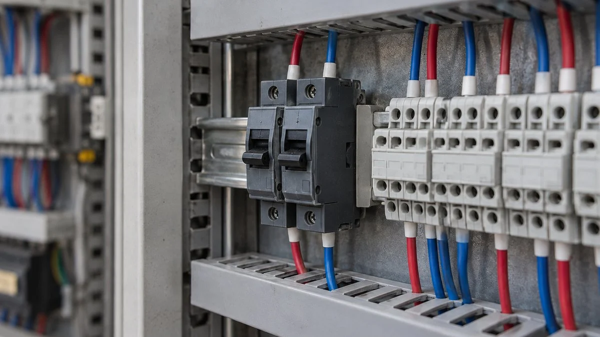
Even with the right current and trip characteristic, a CP will not perform as expected outside its rated panel temperature or side-by-side mounting conditions. Check the ambient temperature range, any required current derating, mounting orientation, and spacing from neighboring devices in the documents for the model you choose.
Terminal type, suitable wire sizes, crimp terminals, tightening torque, and terminal covers are also part of selection. A small outline that fits the old location is not enough; check wire bending space and tool access so the CP can be installed without strain.
A checklist so that the remaining conditions are not skipped once the amp rating is chosen.
← Scroll sideways to see the full table →
| Specification | What to check | Information you need |
|---|---|---|
| Supply and voltage | AC/DC, operating voltage, polarity and specified connection | Power supply specs and single-line/wiring diagram |
| Rating and time characteristics | Continuous current, normal inrush, what the load can tolerate | Load current waveform and trip curves |
| Breaking capacity | Prospective short-circuit current at the installation point, test conditions | System conditions and the rating table for the model |
| Coordination | Upstream devices, power supply current limiting, healthy branches | Maker's combination data |
| Environment and mounting | Panel temperature, side-by-side mounting, orientation, vibration | Layout drawing and operating conditions |
| Connections | Wire, terminals, tightening, covers | Installation instructions and part specs |
| Reset and signals | Manual/remote reset, alarm/auxiliary contacts, restart conditions | Operating specs and the stop/recovery sequence |
If conditions are not settled, do not decide by simply raising the candidate's current rating. Gather the load and power supply information and ask the maker.
Auxiliary and alarm contacts do different jobs: an auxiliary contact typically reports the ON/OFF state of the main contacts, and an alarm contact reports a trip. Check the contact type and its state in normal and fault conditions, its signal rating, and what happens to the signal if its supply is lost.
No alarm on the panel screen does not prove the CP has not operated. Check on the model code and the sequence diagram whether the signal covers trips only or manual OFF as well, and whether the auxiliary contact is actually fitted.
After a Trip: Resetting the CP vs. Restarting the Machine
After a trip, find and remove the cause, such as a faulty load or damaged wiring, before the CP is reset. Switching back on repeatedly while the cause remains can repeat the fault and spread damage to the CP and the equipment.
Some CPs are reset by hand, some reset automatically, and some electronic types reset on an external signal, so follow the instruction manual for the model. Thermal types may also need to cool before they can be reset; do not assume every model is ready after the same waiting time.
"Auto reset" (自動リセット, jido risetto) does not necessarily mean the main circuit switches back on by itself. Mitsubishi Electric uses the term for the CP30-BA because its handle moves to OFF when it trips. With the alarm switch (AL) option, the handle stops at the trip position, between ON and OFF.
In other words, the mechanism becoming ready for the next operation and the main circuit reclosing automatically are different events. Some electronic CPs also distinguish "ready to reset" from "output ON," so read the state descriptions in the manual.
Even where a long stop is costly, as with an aquarium oxygen pump, automatic recovery is not a blanket answer. Weigh the danger of restarting with the fault still present against the impact of the stop, and decide the design with alarms, monitoring, and backup in mind.
A drill that stops on overcurrent shows the other side: if the tool starts spinning the moment protection resets, someone can be hurt. Restoring the protective device, restoring control power, confirming safety, and giving the run command need to be separate steps, according to the machine's risk.
In the drill example, the design keeps the spindle stopped even when power is available again.
← Scroll sideways to see the full figure →
A concept chart of keeping the operations separate. It is not a wiring diagram for a safety circuit and does not define required safety performance; design follows each machine's risk assessment and applicable standards.
Undervoltage detection or shunt tripping and preventing a machine from restarting when power returns are also separate functions. A CP does not necessarily include them as standard, so check the product specifications for the accessory, its operating voltage, holding conditions, and operating circuit.
Releasing an emergency stop and starting normal operation are handled by the machine's safety design. A CP covers only part of overcurrent protection. Protection against electric shock and unexpected restart comes from combining the right devices and controls.
Before adopting a design, confirm normal startup, stopping, alarms, and the reset sequence with the intended load connected. Do not create deliberate short circuits in the field or bypass protective devices; the scope and method of verification follow the maker's and the facility's test procedures.
Checklist Before Replacing or Re-Rating a CP
- Device type confirmed from the datasheet: CP (JIS C 4610 / IEC 60934 / UL 1077) or wiring breaker (JIS C 8201-2-1 / IEC 60947-2 / UL 489)
- Full model code read: poles, elements (e.g., 2P1E), internal accessories, trip curve, rated current
- AC or DC, operating voltage, polarity, and specified connection
- Normal current per branch and the inrush peak and duration
- Trip curve checked against the inrush and against what the load can tolerate
- Prospective short-circuit current at the installation point vs. breaking capacity under the right standard and voltage
- Upstream device and power supply current limit checked for coordination
- Panel temperature, derating, mounting orientation, and spacing
- Terminals, wire sizes, tightening torque, and covers
- Auxiliary or alarm contacts: fitted, wired, and what they signal
- Reset method, and restart conditions decided separately from the CP reset, based on the machine's risk assessment
- Cause of repeated trips found before any change to a larger rating
Questions for the Japanese Supplier
- What is the exact model code of each CP on the drawing, and which standards and certifications (JIS C 4610, IEC 60934, UL 1077, CSA) does it carry?
- Which trip curve (instantaneous, medium-speed, low-speed, inertial delay) was chosen for each branch, and why?
- What are the normal current and the inrush peak and duration of each load?
- What is the rated output and current-limiting behavior of the DC power supply, and has selective tripping of the CPs been confirmed with it?
- What breaking capacity is required at each CP location? Does any CP rely on backup protection, and if so, from which upstream device and under what combination conditions?
- Are auxiliary or alarm contacts fitted, and how are they used in the control sequence?
- After a CP trips and is reset, what conditions and commands are needed before the machine restarts?
- Which locally available CPs, if any, do you approve as replacements?
Sample Inquiry Email
Subject: Circuit protector CP3 on drawing E-012: replacement and trip question
Hello [Name],
On the [machine name] control panel, circuit protector CP3 (24 V DC branch to the solenoid valves, drawing E-012) trips at almost every startup. Before we change anything, could you please confirm the following?
- The exact model code of CP3, including its trip curve, and its certifications
- The normal and inrush current of the loads on this branch
- Whether a different trip curve or rating is acceptable, and which models you approve if we source locally
- The rated output and current-limiting behavior of the 24 V power supply
We will not increase the rating or change the device until we hear from you. Photos of the nameplate and the trip indication are attached.
Best regards,
[Your name]
The machine name, drawing number, and CP number in this email are fictional placeholders.
Limits of This Guide
- This guide explains terms and what to check. It is not a design method or a work procedure. Protection design, resetting, and restart decisions belong to the equipment maker and the people responsible for electrical safety at your site
- Model codes, ratings, and certifications vary by maker, series, and catalog edition. The Mitsubishi Electric and Omron examples here illustrate the kind of information to look for; always use the current datasheet for your exact model
- A CP's standard does not guarantee acceptance under your local electrical code. Whether a UL 1077 or IEC 60934 device is acceptable in a given position depends on local rules and the inspector
- The current calculations and waveforms in this article are fictional examples
FAQ
Can a circuit protector replace an NFB (MCCB)?
No, not just because the amp rating matches. An NFB protects wiring and a CP protects equipment. Check what the circuit needs to protect, the applicable standard, voltage, breaking capacity, and combination conditions before choosing either.
Does a circuit protector trip as soon as the current exceeds its rating?
Not necessarily. The trip time depends on the multiple of rated current, how long it lasts, and the trip curve chosen. Read the maker's time-current curve together with temperature and mounting conditions.
Can a circuit protector detect earth leakage?
An ordinary overcurrent CP does not do the job of leakage protection, which detects an imbalance between outgoing and return current. Where leakage protection is needed, select an ELB (RCD) with a suitable sensitivity and trip time, and decide how it shares protection with the CP.
If a CP is "auto reset," will the machine restart by itself?
Not necessarily. "Auto reset" can describe the handle or internal mechanism returning to a ready state, not the main circuit switching back on. Check the reset operation and output state for the exact model after the cause has been removed.
What is the difference between 2P1E and 2P2E?
Both have two poles. P is the number of poles that switch, and E is the number of overcurrent trip elements, so 2P1E senses overcurrent on one pole and 2P2E on both. Choose according to the grounding system and the internal connection diagram, including any accessories.
Why did other devices stop when only one branch had a fault?
The upstream device may have tripped at the same time, or the shared DC power supply may have limited its current and dropped its voltage. Check the supply capacity, wiring, and CP characteristics together, not just the faulty branch.
A CP keeps tripping. Can I just fit the next size up?
Find the cause first: short circuit, overload, inrush, or temperature. A larger rating may stop the trips but also stop the CP from interrupting a fault fast enough to protect the load or wiring, so review the selection from the specifications.
Sources
- Japanese Standards Association, JIS C 4610:2005 preview (Japanese): title, scope, basis in IEC 60934:2000
- BSI, Circuit-breakers for equipment (CBE) and SIS, IEC 60934:2019: scope of IEC 60934
- Mitsubishi Electric Automation, CP30 circuit protectors, Low Voltage Power Distribution Selection Guide, edition 18 (2018): model code, rating range, UL 1077 and IEC/JIS breaking capacities
- Mitsubishi Electric, circuit protector catalog, October 2019 (Japanese): specifications, trip characteristics, auxiliary contacts
- Mitsubishi Electric FAQ, CP30-BA handle position after a trip (Japanese): auto reset and trip indication
- Mitsubishi Electric FA e-learning, circuit protectors (Japanese): main purpose of CPs
- Mitsubishi Electric, earth leakage circuit breakers (Japanese): ZCT detection
- Fuji Electric FAQ, circuit protectors and wire protection (Japanese)
- Fuji Electric FAQ, miniature circuit breakers vs. circuit protectors (Japanese)
- Fuji Electric FAQ, 2P1E vs. 2P2E (Japanese)
- Schneider Electric FAQ, UL 1077 supplementary protectors: not for branch-circuit protection
- Omron, S8V-CP ratings and performance (Japanese): electronic CP and power supply selection
- E-T-A, thermal circuit protectors (Japanese) and electronic circuit protectors (Japanese)
- Oriental Motor, motor protection devices (Japanese)
- Omron, manual reset vs. automatic reset (Japanese): unexpected startup and risk assessment
Original article in JapaneseThis guide is adapted from a MONOSCOPE article written for readers in Japan: サーキットプロテクタとは?NFB・ヒューズとの違いと選定・復帰の注意点
About the editor
 MONOSCOPE EditorFOUNDER & EDITOR
Spent about ten years at a plant equipment maker and a plant engineering company, proposing, designing, and commissioning equipment, then moved into web marketing. Now a web consultant for B2B manufacturers, helping them explain their products and technology. Licensed in Japan as an Energy Manager and a Third-Class Chief Electrical Engineer.
Has run an engineering blog since 2017 (500+ articles) and a Japanese YouTube channel with about 20,000 subscribers. Each English guide is written from the Japanese shop-floor point of view and checked against the cited standards.