Star-Delta Starter: 1/3 Current, Torque, Timer Settings
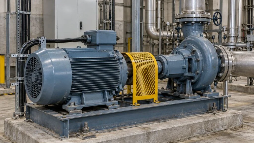
A pump skid or compressor from Japan arrives with a starter panel marked "Y-Δ始動" (star-delta starting). Years later the motor fails, and the replacement on the shelf has the same kW rating but a different nameplate. Can it go straight onto the existing panel? Can the timer stay as it is? The answers depend on what the "1/3" in star-delta really means.
The short answer: a star-delta (wye-delta) starter starts a three-phase induction motor with its windings connected in star (Y), then switches them to delta (Δ) once the motor has accelerated. In star, the line current at start is one-third of what the same motor would draw if started direct-on-line in delta on the same supply. Starting torque also falls to about one-third. The one-third is not a fraction of the rated running current, and it does not mean the panel parts, cables, or energy use can all be cut to a third.
This guide covers how the connection works, where the 1/3 comes from, how to think about the star time and the changeover gap, when the method fits, and what to check before replacing a motor on a star-delta panel. It ends with a checklist, questions for the Japanese supplier, and a sample email.
Contents
What Is Star-Delta Starting?
When you start a squirrel-cage three-phase induction motor from standstill at full voltage, it draws a large current for a short time. This is direct-on-line (DOL) starting, called jikaire shido (直入れ始動) on Japanese drawings. Depending on the supply, that current can cause a voltage dip that other equipment notices.
The high current is not simply the mechanical effort of getting the shaft moving. It comes from the electrical state of an induction motor whose rotor is not yet turning, which draws much more current than during rated running. How many times more depends on the motor design and starting conditions. You may see figures such as "8–10 times," but the multiple is not fixed. Start from the manufacturer's data: starting current, starting torque, and allowable starting time.
Star-delta starting is a type of reduced-voltage starting (gen-den'atsu shido, 減電圧始動). It lowers the voltage across each winding only while the motor starts. Instead of changing the supply's line voltage, it changes how the three windings are connected.
In a star connection, one end of each of the three windings is tied together at a common point, and the other ends go to the three-phase supply. In a delta connection, the windings form a triangle, and its three corners connect to the supply.
Conceptual circuit for a balanced three-phase supply. Each rectangle represents the same per-phase winding impedance Z.
What the Motor Needs
For star-delta starting, both ends of every winding must be brought out to the terminal box so the starter can reconnect them. The typical motor has six terminals or leads, though some multi-voltage motors have 12 leads. Six-terminal boxes may be marked U1, V1, W1 and U2, V2, W2; older equipment may use U, V, W and X, Y, Z. Confirm the pairing on the manufacturer's connection diagram rather than assuming it.
The motor must also be rated to run in delta at the supply voltage. Having six terminals is not enough: you cannot wire just any motor for star-delta on any supply. Take a nameplate that reads Δ230 V / Y400 V. On a 400 V supply, this motor is meant to run continuously in star. Switching it to delta on 400 V would exceed the winding rating, so read the voltage and the connection on the nameplate as a pair. For Japan's 200 V and 400 V classes, see Japanese industrial voltages: 200 V and 50/60 Hz.
Related: Japan Industrial Voltage: 200V 3-Phase and 50/60 Hz Guide
Why Starting Current Drops to One-Third
To compare currents, separate the line current, which flows in the supply conductors, from the phase current, which flows through one winding. The relationship between the two differs between star and delta.
The model below assumes a balanced three-phase supply with line voltage VL, and |Z| as the magnitude of the per-phase impedance at start. It compares star and delta for the same motor at the same standstill condition.
In star, each winding sees 1/√3 of the line voltage. The current through one winding is also the current in the supply line, so:
In delta, the full line voltage appears across each winding. In a balanced system, the line current is also √3 times the phase current:
One factor of 1/√3 comes from the lower winding voltage, and another from the line-to-phase current relationship. Together they give 1/3. Keep the two comparisons apart: the current through one winding falls by 1/√3, while the line current on the supply side falls by 1/3.
Same VL and |Z|, balanced three-phase supply, same starting condition.
As a worked example, assume a 200 V line voltage and a per-phase |Z| of 2 Ω. In star, each winding sees about 115.47 V, and both the phase current and the line current are about 57.74 A.
Comparing 57.74 A with 173.21 A confirms the ratio of about 1/3. Once the motor speeds up, its electrical state changes, so the current after switching to delta will not always be 173.21 A.
When you compare measured values, make sure both readings were taken at the same place: on the supply lines or inside the delta loop on the winding side.
Starting Torque Also Drops to One-Third
The price of lower current is lower starting torque. If you approximate torque as proportional to the square of the voltage, at the same frequency and starting condition, star-start torque is also about one-third of delta DOL torque.
To accelerate, the motor torque must exceed the torque the load demands. If the margin is small, acceleration takes longer. If the load torque is larger, the motor cannot reach adequate speed in star.
Qualitative comparison. Curve heights show which is larger, not actual motor data.
For this reason, star-delta suits machines that can start with no load or a light load. Even pumps differ by type and operating condition, so do not assume every pump has the same starting load.
Switching Sequence and Timer Settings
A common three-contactor starter uses a main (line) contactor, a star contactor, and a delta contactor. The main contactor and star contactor close, and the motor accelerates in star. The star contactor then opens, the delta contactor closes, and the motor settles into normal running.
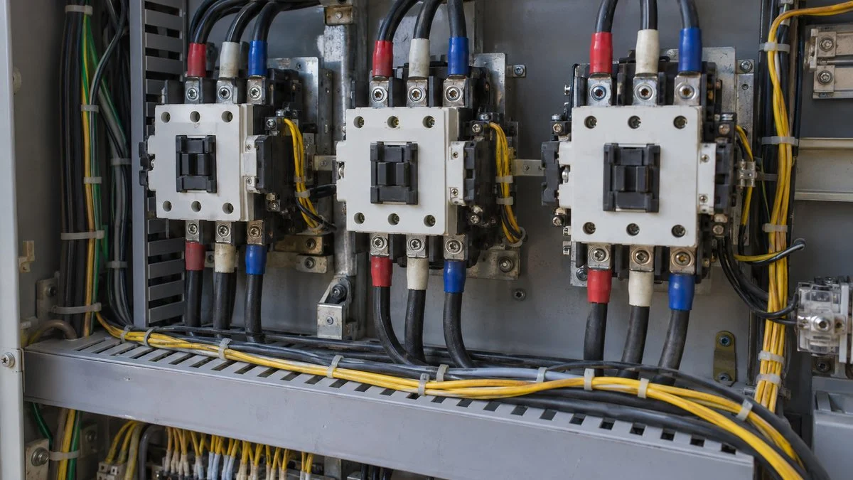
If the star and delta contactors close at the same time, they can short-circuit the supply. Do not rely on the timer alone: the contactor sequence has to work together with electrical and mechanical interlocks.
Example of an open-transition, three-contactor starter. The horizontal axis shows sequence, not actual seconds.
The star time is set from the motor and load characteristics so the motor accelerates sufficiently before changeover. The dead time is set from the starter maker's specifications so that the star contactor has fully opened before the delta contactor closes. Some star-delta timer relays fix the dead time; ABB's CT-YDEW, for example, uses a fixed changeover of about 50 ms after an adjustable star time. Treat that as one product's design, not a general setting.
A single number such as "switch about 0.5 seconds after start" cannot serve as a universal setting. Switching too early means the contacts open and close while a large current is still flowing. Simply running longer in star does not solve the problem either: check that acceleration has not stalled and that the start stays within the motor's allowable starting time.
In an open-transition starter, the motor is briefly disconnected from the supply. When delta closes, the motor's residual voltage and the supply voltage interact, which can cause a current surge and a mechanical jolt. Even if the starting current is cut to one-third, the current at the moment of changeover is not necessarily held to the same ratio.
The same principle of preventing simultaneous closing applies to interlock circuits in general. When you troubleshoot a starter that will not run, trace which condition is not satisfied. Do not defeat the protective conditions just to make it run.
Related: Interlock Circuit Diagrams: How to Read Japanese Drawings
When to Use Star-Delta Starting
1. Effect on the supply. The first question is how the starting current affects the power supply. The same motor causes a different voltage dip depending on the capacity of the incoming power equipment, the system impedance, and the cable length. Starting a large motor on a small transformer, for example, can affect other loads. Do not decide from the motor kW alone; look at the transformer capacity and characteristics, the other loads running at the same time, and the allowable voltage fluctuation together.
2. Can the reduced torque accelerate the load? Even if the supply side is fine, the starter fails its purpose if the motor will not turn in star or stalls partway. Besides the load itself, the inertia of the rotating parts and the number of starts matter. For machines that take a long time to accelerate or start frequently, also check the motor temperature rise and the contactor duty.
3. Is the motor suitable? Confirm that the motor can run in delta at the supply voltage and that its winding ends can be switched. You cannot force a motor with a different rating onto an existing panel just to match its starting method.
You may see kW thresholds quoted, such as "11 kW and above at 200 V" or "30 kW and above at 400 V." Deciding on those numbers alone misses all three points above. Check the utility's supply conditions, the plant's design standards, and the manufacturer's selection data before choosing a starting method.
Comparison of starting methods. Choose based on the required acceleration, supply conditions, and normal operation.
Star-delta is not an energy-saving device that cuts running power to one-third. After acceleration, the motor drives the load in delta and draws electrical power according to the shaft power the load requires.
If you want to vary speed to match flow or airflow, consider speed control separately from the starting method. Soft starters and inverters (variable frequency drives, VFDs) do different jobs; you cannot swap one for the other just because both "limit current."
Cost comparisons also need more than the contactor price. Compare at the system level: panel space, wiring, controls, protection, maintenance, and the effect of the changeover on the machine.
Replacing a Motor on a Star-Delta Starter
Motor: Nameplate and Terminal Box
When replacing a motor, matching the kW is not enough. Check the voltage, frequency, number of poles, rated current, and connection. Differences in efficiency can change the current characteristics at the same output, so you may need to recheck compatibility with the existing starter.
Check the nameplate (meiban, 銘板) and the terminal box. Are the required winding ends brought out, and can the motor run in the specified connection? Even if the frame fits the mounting, the number of terminals, terminal screws, and cable entries may differ.
Even when replacing only the motor, check the electrical and mechanical requirements together.
Panel: Protection Ratings and Settings
In the panel, check the type and setting range of the circuit breaker, contactors, and overload protection. A starting current of one-third does not mean you can shrink every device and cable to one-third of the rating.
A thermal overload relay may measure either line current or winding (phase) current, depending on where it sits in the circuit. Schneider Electric's guidance, for example, sets an overload inside the delta loop at 0.58 times the motor's full-load current, and an overload upstream in the supply at 100%. Do not apply one multiplier to every circuit; confirm the setting from the maker's circuit diagram and selection table. For background on breakers and overload devices on Japanese panels, see NFB, MCCB, and ELB breakers in Japan and shock relay vs. overload relay. Keep the starting contactors and the protective devices separate in your mind: one starts the motor, the other protects the circuit when something goes wrong.
Related: Thermal Trip: Why Thermal Relays Trip and How to Reset
Changing the Motor Size
Going larger: re-evaluate whether the current and starting time stay within the range of the existing equipment. Also check the voltage drop along the existing cable run, heat dissipation in the panel, and space for any added parts.
Going smaller: check the setting range of the protective devices and the size of the connections as well. Rather than forcing a heavy existing cable into a new, smaller terminal, agree on an acceptable connection method with the installer.
Load: Shaft Power and Starting Conditions
On the load side, confirm the shaft power the pump or other machine needs and its load at start. A smaller motor does not automatically save energy; understand the required power and the operating point first. A low current during normal running does not let you skip checks on starting torque and transient conditions.
Controls, Test Run, and Records
In the control circuit, review the star time, dead time, interlocks, and contact status checks. Before copying the old settings to the new motor, confirm how the start actually progresses and what the allowable limits are.
After any wiring change, check the direction of rotation and the load condition during the specified test run. For why rotation reverses, see pump running backwards: phase sequence. The work itself must follow the site's procedures for stopping, isolating, and verifying the absence of voltage.
In the test-run record, log current and time separately for the star period, the changeover, and normal running. If the breaker trips only at the moment of changeover, investigate that separately from a case where the normal load current is too high.
Finally, keep the updated nameplate data, protection settings, timer values, and circuit diagrams together in their as-changed state. Making sure the next inspection does not find old-motor documents mixed with new settings is part of the replacement job.
Checklist: Replacing a Motor on a Star-Delta Panel
Use this list before the new motor is wired in. It summarizes the points above; the actual decisions belong to the people responsible for the electrical design and the equipment.
| Item | What to confirm | Where to find it |
|---|---|---|
| Voltage and connection | Motor is rated to run in delta at the supply voltage (not star-only at that voltage) | Nameplate, maker's data |
| Terminals | Six (or more) winding ends brought out; terminal marking and pairing | Terminal box, maker's connection diagram |
| Frequency, poles, rated current | Match the existing panel and load; note any change in rated current | Nameplate, old motor records |
| Starting data | Starting current, starting torque, allowable starting time | Maker's datasheet |
| Load at start | Load torque and inertia can be accelerated on star torque; number of starts | Machine data, operating conditions |
| Contactors and breaker | Ratings and duty still fit the new current and starting time | Panel drawings, selection tables |
| Overload relay | Position (in the delta loop or in the supply line) and setting based on that position | Circuit diagram, relay maker's guidance |
| Cables and connections | Voltage drop, terminal size, acceptable connection method | Cable schedule, installer |
| Timer | Star time and dead time reviewed for the new motor, not copied blindly | Control drawings, starter maker's specs |
| Interlocks | Electrical and mechanical interlocks between star and delta contactors intact | Control drawings, panel inspection |
| Test run | Rotation direction; current and time logged for star, changeover, and running | Test-run record |
| Documents | Nameplate data, settings, timer values, and diagrams updated together | Maintenance records |
Questions for the Japanese Supplier
- Which connection is the motor designed to run in at our supply voltage, and is it suitable for star-delta starting?
- Can you send the motor's terminal diagram and its starting current, starting torque, and allowable starting time?
- What star time and dead time were set at the factory, and how were they determined?
- Where is the overload relay in the starter circuit (inside the delta loop or in the supply line), and what setting do you recommend for the new motor's rated current?
- Do the existing contactors, breaker, and cables remain within their ratings with the replacement motor?
- Was the starting method chosen because of supply conditions at the original site? Do those conditions apply at our site?
Sample Email to the Supplier
The equipment number and details below are fictional. Replace them with your own.
Subject: Replacement motor for P-201 star-delta starter: request for data
Hello,
We plan to replace the motor on pump P-201 (your order no. XXXX), which uses a star-delta starter in your panel. The replacement motor has the same kW but a different nameplate. Before we connect it, could you please confirm the following?
1. The connection the original motor runs in at our 400 V supply, and whether the new motor (nameplate attached) can be used for star-delta starting on this panel.
2. The factory settings for the star time and the star-delta dead time, and the basis for them.
3. The position of the overload relay in the circuit and the recommended setting for the new motor.
4. Whether the existing contactors, breaker, and cables remain within their ratings.The current panel drawings and the new motor's datasheet are attached. Thank you for your support.
Best regards,
Limits of This Guide
- The 1/3 ratios are theoretical values for a balanced supply and the same standstill condition. Real motors and loads differ; use the maker's data.
- This guide covers the common open-transition, three-contactor starter. Other starter designs behave differently at changeover.
- Timer, overload, and breaker values mentioned here are examples from specific products or makers, not settings to copy.
- It does not replace electrical design, local codes, or site safety procedures. Panel and motor work must follow the site's procedures for stopping, isolating, and verifying the absence of voltage.
FAQ
Does a star-delta starter start the motor at one-third of rated current?
No. The comparison is with the line current the same motor would draw if started direct-on-line in delta on the same supply. Rated running current is a different condition, so the starting current is not one-third of rated current.
Can I save energy by leaving the motor in star?
No. A star-delta motor is designed to drive its load in the specified delta connection after acceleration. Running in star can cause a torque shortfall or overheating, so do not lock the motor in star to save energy.
What should the star-delta timer be set to?
There is no single value. Check the star time needed for acceleration and the dead time for the contactor changeover separately. Both depend on the motor, the load, and the starter, so a fixed figure such as 0.5 seconds cannot be applied everywhere.
If a motor has six terminals, can it be used for star-delta starting?
Only if it can also run in delta at the supply voltage. Besides having switchable winding ends, the motor must be rated for delta at that voltage. Check the nameplate voltage and connection and the maker's specified circuit.
Is the current surge at changeover also limited to one-third?
Not necessarily. In an open-transition starter, the motor's residual voltage and the supply interact at changeover and cause a transient current. Look at starting, changeover, and normal running separately, and confirm that the starting method, contactors, and protection fit each stage.
Sources
- Star-delta starting reduces starting current to 1/3 of DOL: Mitsubishi Electric FA FAQ 15032, "What is star-delta starting?" (Japanese)
- Motor terminal structure and connections: Mitsubishi Electric, three-phase motor general catalog, p. 61 (Japanese)
- Motor starting methods: Fuji Electric, "Motor starting methods" (Japanese); Fuji Electric, motor starting method selection and technical data (Japanese)
- Starting methods and reduced-voltage starting: Mitsubishi Electric e-learning, motor starting methods (Japanese); Mitsubishi Electric e-learning, reduced-voltage starting connections and selection (Japanese)
- Three-contactor star-delta starters: Schneider Electric, TeSys Giga star-delta starters
- Overload relay position and setting (0.58 × FLC in the delta loop, 100% upstream): Schneider Electric FAQ FA173001
- Motor voltage and star-delta connection: ABB, Softstarter Handbook
- Fixed 50 ms star-delta changeover in a timer relay: ABB, CT-YDEW star-delta timer data sheet
Original article in JapaneseThis guide is adapted from a MONOSCOPE article written for readers in Japan: スターデルタ始動法とは?電流1/3の理由・トルクと切替時間、更新時の確認点
About the editor
 MONOSCOPE EditorFOUNDER & EDITOR
Spent about ten years at a plant equipment maker and a plant engineering company, proposing, designing, and commissioning equipment, then moved into web marketing. Now a web consultant for B2B manufacturers, helping them explain their products and technology. Licensed in Japan as an Energy Manager and a Third-Class Chief Electrical Engineer.
Has run an engineering blog since 2017 (500+ articles) and a Japanese YouTube channel with about 20,000 subscribers. Each English guide is written from the Japanese shop-floor point of view and checked against the cited standards.