Thermal Trip: Why Thermal Relays Trip and How to Reset
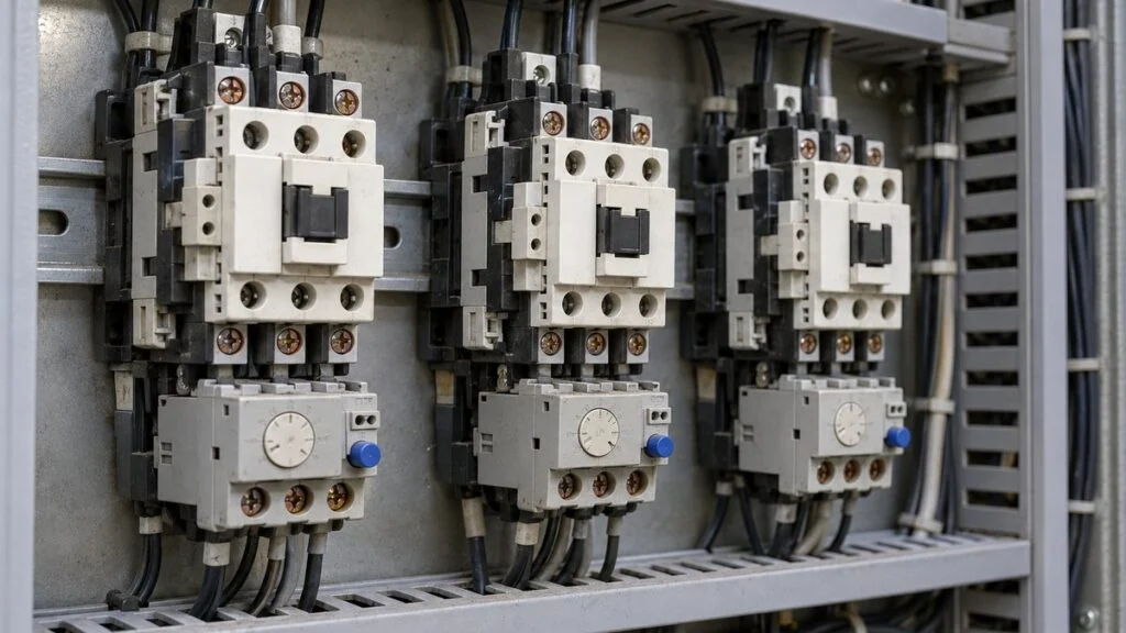
A pump or conveyor built in Japan stops in the middle of a shift. The operator panel shows a Japanese alarm, サーマル異常 (samaru ijo, "thermal fault") or "THR トリップ" (THR trip), and pressing the start button does nothing. On the shop floor in Japan, people say "the thermal dropped" (サーマルが落ちる, samaru ga ochiru) or "the thermal blew" (サーマルが飛ぶ, samaru ga tobu).
All of these describe a thermal trip: the motor drew more than its rated current for too long, the thermal overload relay sensed the heat, opened the magnetic contactor's coil circuit, and stopped the motor. The motor stays off until someone removes the cause and resets the relay.
This guide explains the Japanese terms you will see on drawings and alarm screens, how a thermal overload relay trips, how long it takes at a given overload, what is typically checked after a trip, and how the current setting is chosen. It also covers the most common causes on pumps and how an inverter's electronic thermal protection differs. It ends with a checklist and questions to send to the Japanese equipment supplier.
- Do not keep pressing the start button. If the cause is still there, the relay trips again and the motor windings take more heat each time.
- Look at the thermal overload relay's trip indicator and reset button, and check whether the upstream molded case circuit breaker (MCCB) or earth leakage breaker (ELB) has also tripped.
- Leave work inside the panel, including measurements, to qualified electrical staff, who de-energize, lock out, and tag the circuit under your site's procedure first. If nobody can find the cause, hand it over to them (see "What Happens After a Thermal Trip" below).
Contents
- Japanese Terms You Will See
- How a Thermal Overload Relay Trips
- How Long Before It Trips? Trip Times by Overload
- What Happens After a Thermal Trip
- How the Current Setting Is Chosen
- Common Causes of Thermal Trips on Pumps
- Inverter (VFD) Electronic Thermal vs. Thermal Overload Relay
- Checklist and Questions for the Japanese Supplier
- Limits of This Guide
- FAQ
- Sources
Japanese Terms You Will See
Japanese drawings, panel labels, and HMI screens use a handful of terms for the same device and the same event. This table maps them to the English terms used in the rest of this guide.
What you see on the drawing or screen, and what it means.
| Japanese | Reading | English |
|---|---|---|
| サーマルリレー / THR | samaru rire | Thermal overload relay. "THR" is the usual symbol on Japanese drawings |
| 熱動継電器 / 熱動形過負荷継電器 | netsudo keidenki | Formal names for the same device (thermal relay / thermal overload relay) |
| サーマルが落ちる・飛ぶ・動作した | samaru ga ochiru / tobu | "The thermal tripped." Shop-floor ways to say thermal trip |
| サーマル異常 / THR トリップ | samaru ijo | Thermal fault / THR trip alarm. Usually a relay trip, but sometimes an inverter overload alarm |
| 電磁接触器 (MC) | denji sesshokuki | Magnetic contactor |
| 電磁開閉器 | denji kaiheiki | Magnetic motor starter (contactor + thermal overload relay) |
| 配線用遮断器 (MCCB / NFB) | haisen-yo shadanki | Molded case circuit breaker |
| 整定電流 / 整定値 | seitei denryu / seitei-chi | Current setting (the dial value) |
| 欠相 | kesso | Phase loss (single-phasing) |
| 拘束 | kosoku | Locked rotor (the motor cannot turn) |
| 電子サーマル | denshi samaru | Electronic thermal overload protection inside an inverter (VFD) |
On a phone, scroll the table sideways.
"Trip" itself is a general word for a protective device stopping a circuit or machine automatically. Japanese engineers use トリップ (torippu) the same way for breakers and turbines. For the Japanese names of circuit breakers, see NFB Breaker vs. MCCB vs. ELB: Japanese Circuit Breaker Terms.
How a Thermal Overload Relay Trips
A thermal overload relay protects motors and other electrical equipment from overload and is used mainly on three-phase induction motors. When too much current flows for too long, it stops the motor before the windings burn. Inside, it combines a heater with a bimetal strip, two metals with different thermal expansion bonded together. Omron's catalog divides the main parts into three: the heat element (heater and bimetal), the adjustment dial, and the contacts. On some models, heat elements come in different current ranges, and the element is swapped for one that fits when the adjustment range does not match the motor.
Heat from the current bends the bimetal, which opens a contact and drops out the magnetic contactor.
The relay's heaters sit in the main circuit; the normally closed contact (95-96) sits in the contactor coil circuit. Terminal numbers follow the Omron J7TC connection diagram as an example. Check the markings on the actual relay.
The relay itself cannot interrupt the motor's main circuit. Its normally closed (NC) contact, 95-96, is wired into the coil circuit of the magnetic contactor (MC). When the relay trips, that contact opens, the coil loses power, and the contactor's main contacts open to stop the motor. The normally open (NO) contact, 97-98, typically drives a trip lamp or a PLC input, which is where the サーマル異常 alarm on the HMI usually comes from.
Power flows through the circuit breaker, the magnetic contactor, and the thermal overload relay to the motor.
Simplified main circuit. This example shows a 2-element relay (heaters in two phases). Where phase-loss protection is needed, a 3-element relay with phase-loss protection is used.
Because it works by heat, the relay responds with a delay. A Mitsubishi Electric technical report notes that for bimetal-type motor starters, the operating time under overload is roughly inversely proportional to the current. That delay lets the motor ride through its short inrush at starting and trips only on a sustained overload. It also means a thermal overload relay is not what protects the circuit from short circuits. That job belongs to the circuit breaker or fuse, and earth leakage belongs to the ELB. A thermal-magnetic MCCB uses a bimetal for overload and an electromagnet for short circuits and is reset with its handle once the cause is fixed. A fuse element melts from the heat of the current and is replaced with a new one of the same rating. An ELB uses a zero-phase current transformer to compare outgoing and returning current, and many models also include overcurrent protection; it is switched back on after the leak is repaired. Fuji Electric's selection guide splits the roles the same way: the magnetic starter protects the motor from overload, and breakers protect the circuit from short circuits.
Most thermal overload relays have a manual reset button. Some can be switched to automatic reset, which matters for safety (see below).
A shock relay looks similar in a Japanese panel but protects the driven machine rather than the motor windings. The differences, and how trip class is defined, are covered in Shock Relay vs. Overload Relay: How It Works and Settings. For fuses and circuit protectors, see Circuit Protector (CP) vs. Circuit Breaker (NFB) and Fuse.
How Long Before It Trips? Trip Times by Overload
How much current, for how long, before the relay trips? The answer comes from the relay's trip class, which manufacturers state according to IEC 60947-4-1 (JIS C 8201-4-1 in Japan). Trip time depends on the trip class and on whether the relay starts cold or already warm, so no single number applies to every relay.
Multiples are of the current setting on the dial. The right-hand column is a worked example, not a manufacturer value.
| Multiple of current setting | Required behavior | Starting state | Current at 0.75 kW, set to 3.8 A |
|---|---|---|---|
| 105% | No trip within 2 hours | Cold | About 4.0 A |
| 120% | Trips within 2 hours | Warm | About 4.6 A |
| 150% | Trips in under 2 minutes | Warm | 5.7 A |
| 720% (locked rotor) | Trips in more than 2 s and up to 10 s | Cold | About 27 A |
Values for trip class 10A, three-pole load, 20°C (68°F) ambient, from the ratings table in Omron's J7TC catalog. In Fuji Electric's data, models TR-10 and larger are trip class 20, tripping in 6–20 s at 720%. The current column applies 3.8 A, the reference full-load current for a 200 V, 0.75 kW motor in the same catalog. Confirm actual values on the nameplate and the relay documentation.
The worked example simply multiplies the 3.8 A setting: 3.8 × 1.2 = 4.56 A, 3.8 × 1.5 = 5.7 A, and 3.8 × 7.2 = 27.36 A. A small overload takes a long time to trip the relay; a locked-rotor current trips it in seconds. Current slightly above the setting does not trip it right away.
That timing is a useful clue. If the motor tripped after running for tens of minutes, suspect a mild overload that kept going. If it tripped right after starting, suspect a locked rotor, phase loss, or a long starting time.
What Happens After a Thermal Trip
A trip means the motor or the driven equipment is overloaded or in an abnormal state. The five steps below are the usual order of response. This is an overview of what gets checked and who decides, not a work instruction: for the actual procedure, follow the relay's instruction manual and your site's electrical safety rules.
Reset is step 4. Pressing it before the cause is removed only leads to another trip.
Running and stopping repeatedly without finding the cause overheats and damages the motor windings.
Make It Safe First
A stopped motor is not necessarily a safe motor. A relay set to automatic reset recovers by itself once it cools, and in some circuits the motor then restarts on its own. The instruction manuals from both Fuji Electric and Omron warn that with automatic reset in a two-wire control circuit, the motor restarts automatically.
Before anyone works on the machine, the circuit is de-energized and isolated under the site's lockout/tagout procedure (in the US, OSHA 29 CFR 1910.147 sets the requirements), and the area is kept clear. In Japan, the Industrial Safety and Health Regulations require stopping the machine, locking the starting device, and posting a sign before hazardous cleaning or repair (Article 107), and one of three measures (locking the switch, posting a do-not-energize sign, or assigning a watchperson) before inspecting or repairing an isolated electrical circuit (Article 339). Do not touch an energized relay or its terminals.
Find the Cause
The usual suspects are:
- Overload: has the load increased? Sticking or worn machine parts, or a pump running at excessive flow
- Locked rotor: is rotation blocked by debris or a failed bearing?
- Phase loss: is one of the three phases open or poorly connected? The other two phases then carry high current
- Supply: is the supply voltage low or unbalanced?
- Setting or environment: is the current setting wrong, or is the panel too hot?
The check usually starts with whether the motor is running overloaded, which can come from a mechanical problem or a wrong setting. Next come loose terminals, broken wires, and worn contactor contacts that can cause phase loss. If the motor can be run, electrical staff measure all three phase currents with a clamp meter to look for imbalance, and check for low or unbalanced supply voltage. Last, the driven machine (pump, fan, and so on) is checked for debris and whether the shaft turns by hand with power locked out. Anything that blocks rotation keeps high current flowing.
Short circuits are cleared by the MCCB or fuse and earth faults by the ELB, not by the thermal overload relay. If a short circuit or leakage is suspected, check whether the upstream MCCB or ELB has tripped as well.
Narrow down the cause from how long the motor ran before tripping and what you can see on site.
| Cause | Typical symptom | What to check (measurements by electrical staff) | Left to specialists |
|---|---|---|---|
| Overload | Trips after running for a while | Ammeter reading vs. normal value and nameplate rating | Review the load; repair the machine |
| Locked rotor | Trips right after starting; humming | With power off and locked out, does the shaft turn by hand? | Inspect bearings and debris; disassemble |
| Phase loss | Trips at start or while running; humming, vibration | Large difference between the three phase currents? | Inspect terminals, contacts, cables |
| Supply | Other equipment on the same feeder also misbehaves | Voltage and imbalance between phases | Investigate the supply side |
| Setting or environment | Trips in summer or when the panel is hot | Current setting vs. full-load current; panel temperature | Review the setting; improve ventilation |
| Motor deterioration | Keeps tripping with none of the above found | Burning smell or abnormal heat while running | Insulation and winding resistance tests |
Current and trip behavior under phase loss depend on whether the relay has phase-loss protection. Checking current, voltage, and the shaft carries shock and restart hazards, so qualified electrical staff do it under the site's procedures. On a phone, scroll the table sideways.
Motor insulation is tested with an insulation resistance tester (megger) with the power off. Legal minimums differ by country and are only a floor, so judge the result against the motor maker's or your site's criteria. Whether contactor and relay contacts open and close properly can also be checked with a multimeter on the resistance range, with the power off.
Fix the Cause
- Overload: repair the mechanical problem and bring the load back into range
- Phase loss: find and repair loose terminals, broken wires, or bad contactor contacts
- Supply: if the voltage is low or unbalanced, investigate the supply side
- Debris: remove it and clean the machine
Causes can also combine. A loose terminal causes phase loss, the motor keeps running on two phases, and the windings get damaged. Look from several angles and fix everything you find in one go.
Resetting the Relay
Once the cause is removed, the relay is reset, on most models with a reset button. Buttons and indicators vary by model: Fuji Electric's FAQ, for example, says to press the blue reset button on TR-N2 to N8 models and the white one on models such as TR-0N. Trip indication also varies (a white trip bar that retracts, a yellow flag, and so on), so check the manual for that model. Exact reset steps are model-specific; follow the instruction manual rather than any general description.
If the relay will not reset, it is usually one of three situations:
- It won't reset right away: just after a trip the bimetal is still bent, so pressing reset does nothing (trip-free behavior). This is normal, not a fault.
- It won't reset even after waiting: Fuji Electric's FAQ says its relays can be reset once 90–350 seconds or more have passed since the trip, depending on frame size. If it still won't reset after that, the relay is likely faulty. For other makers' relays, check the manual for the wait time.
- It resets but trips again: the cause is still there. Stop running the motor and go back to finding the cause.
After a reset, confirm the equipment runs normally. Check that the running current is well below the setting and balanced across all three phases.
The Fuji Electric and Omron manuals describe how to switch from manual to automatic reset.
Switching method and indicator behavior are examples from the Fuji Electric TK-E02 and Omron J7TC manuals. Check each model.
A two-wire control circuit runs the motor for as long as the run command is present. A three-wire circuit uses push buttons with a seal-in (self-holding) contact, so after the relay resets the motor stays stopped until someone presses start. In a two-wire circuit, even a manual reset restarts the motor immediately if the run command is still on, so the run switch should be off before the relay is reset.
Preventing Repeat Trips
Periodic inspection catches equipment and circuit problems early, and load management prevents overload. The single most useful habit is recording normal running current. If current creeps up before a trip, that is your cue to suspect bearing wear or clogging.
If the cause is unknown, the relay keeps tripping, or it will not reset, stop the motor and hand the problem over to electrical staff. The details in the checklist near the end of this guide speed up their investigation.
How the Current Setting Is Chosen
The current setting (整定値, seitei-chi) determines whether the relay actually protects the motor. Setting it starts with two facts: the motor's full-load current on the nameplate, and the relay's adjustment range. Ambient conditions, load type, relay type, and a test run then refine it. Changing the setting is a decision for electrical staff, based on the equipment documentation and site standards. Turning the dial up on the floor because the relay tripped is exactly what to avoid.
Start With the Motor's Full-Load Current
Find the motor's rated current on the nameplate, in the instruction manual, or in the specifications. Rated current is what the motor draws running continuously at rated output. The Fuji Electric and Omron instruction manuals both say to turn the adjustment dial so that the motor's full-load current lines up with the ▼ mark. The machine builder may specify a different value, though, so check the machine documentation as well.
In the US, the National Electrical Code (NEC 430.32) also caps the overload trip setting for continuous-duty motors: generally 125% of nameplate full-load current for motors with a service factor of 1.15 or more or a temperature rise of 40°C or less, and 115% for other motors. Check the edition and local amendments that apply to your site.
Allow for Ambient Temperature
The relay also picks up heat from its surroundings, so it trips sooner in a hot panel and later in a cold place. Omron's J7TC catalog gives its compensation performance as tripping within 2 hours at 120% current at 40°C (104°F), and at 130% at −5°C (23°F). The manual shows an example of calculating the setting with a correction factor when the ambient is far from 20°C (68°F). If the relay trips only in summer, look at panel temperature and ventilation before touching the setting.
Match the Relay to the Load
Motors that start and stop frequently see repeated short overloads. For those, and for loads with long starting times or inching duty, the answer is a relay designed for that service (such as a type with a saturable reactor), not a higher setting. Mitsubishi Electric's selection guide says that when the starting current and starting time are expected to trip the relay, either use a relay with a saturable reactor or short-circuit the relay only during starting. Fuji Electric notes that loads with long starting times need a delayed-trip type. For star-delta starting, Mitsubishi Electric limits the star-connection time to 10 seconds on the timer and calls for reviewing the equipment selection if it takes longer; see Star-Delta Starter: 1/3 Current, Torque, Timer Settings.
Check the Relay's Range and Elements
Most relays have a specified adjustment range. The Omron J7TC-01-4E2, for example, covers 2.8–4.2 A, which fits a motor with a 3.8 A full-load current. Outside its range, a relay does not meet its rated performance, so choose a model whose range fits.
Check the number of elements too. Mitsubishi Electric's selection table uses the 2-element type as standard but recommends a 3-element type with phase-loss protection (its "2E" type) where phase-loss protection is needed. Conversely, a relay with phase-loss protection used on a single-phase motor can trip when it shouldn't, because one pole carries no current. Omron's guidance is to pass current through all poles in series, or set the dial about 10% higher.
Confirm With a Test Run
After setting the current, run the equipment under real operating conditions. The relay should trip on an overload and should not trip during normal operation. A sequence check, pressing the relay's trip bar, also confirms that the control circuit stops the motor as intended.
If the relay trips at every start, manufacturers give limits on how far to raise the setting: Omron says about 5% or less for the J7TC, and Mitsubishi Electric suggests about 110% of rated current when a motor replaced with an IE3 motor trips. Both apply only within what that product's documentation allows. If it still trips, do not keep raising the setting; switch to a suitable type, such as one with a saturable reactor.
Review the Setting Over Time
The setting is not "set and forget." Review it whenever the motor is replaced, the load changes, or operating conditions or the environment change. During periodic inspections, check terminal screws as well as the setting. Fuji Electric's manual calls for retightening the terminal screws periodically, because loose terminals cause heating and phase loss.
Common Causes of Thermal Trips on Pumps
When a pump motor trips, look at the pump as well as the electrical side. Ebara's pump instruction manuals list the following causes of overcurrent.
Grouping the causes into piping, pump, liquid, and supply makes them easier to track down.
From "Troubleshooting" in Ebara's DN and SCD instruction manuals. The causes listed differ by model.
The easy one to miss is low head causing excessive flow. On many centrifugal pumps, shaft power rises as flow increases, so if the piping has less resistance than designed, current goes up. The frequency item matters for imported equipment: Japan runs on 50 Hz in the east and 60 Hz in the west, so check which one the pump was built for (see Japan's industrial voltage and 50/60 Hz).
The same manuals ask operators to check current and ammeter needle swing daily. Even with current within the rating, a large swing can mean debris is caught in the pump. A needle that swings widely and periodically can also point to surging.
Related: Cavitation vs Air Entrainment in Pumps: Telling Them Apart
Related: Centrifugal Pumps in Parallel: Why Flow Doesn’t Double
For pumps, also record discharge pressure, discharge valve opening, and any change in liquid temperature or type. Lining up current and pressure at the same timestamps makes it easier to tell excessive flow from clogging.
Inverter (VFD) Electronic Thermal vs. Thermal Overload Relay
On motors driven by an inverter (variable frequency drive, VFD), the drive's electronic thermal overload protection (電子サーマル, denshi samaru) may monitor overload instead of a bimetal relay. It measures current electronically, calculates how hot the motor is getting, and stops the motor.
When the panel shows サーマル異常 or an overload alarm, first find out which device acted. If the thermal overload relay shows no trip and the inverter display shows an alarm, the inverter tripped.
Electronic thermal behavior depends on its settings. A Yaskawa Electric FAQ describes motors that burned out even though 150% of rated current was flowing, and gives four causes:
- Electronic thermal protection was disabled
- The motor rated current was set incorrectly
- A general-purpose motor was set up as an inverter-duty motor
- The inverter's power was switched off every time it stopped on overload
The fourth is easy to overlook. The same FAQ says the time to trip at 150% current is about 1 minute from a warm state but about 7 minutes from cold. Because each power cycle restarts the count from cold, the motor can burn out before the drive ever trips. Settings and behavior differ by model, so check the inverter's instruction manual.
Checklist and Questions for the Japanese Supplier
Use this when a thermal trip happens on Japanese-built equipment, or before commissioning.
Information to Record at Every Trip
- Equipment name, relay model, and current setting
- Indications present: relay trip indicator, upstream breaker status, HMI alarm text (photograph Japanese messages)
- Time from start to trip, and the load at that time
- Normal running current and current just before the trip, and whether the relay could be reset
- For pumps: discharge pressure, discharge valve opening, liquid temperature and type
Questions to Ask the Japanese Supplier
- Which relay model and trip class is used, and on what basis was the current setting chosen (nameplate full-load current or a value specified by the machine builder)?
- Is the relay set to manual or automatic reset? Is the control circuit two-wire or three-wire?
- Is the relay 2-element or 3-element with phase-loss protection?
- Which device does each alarm on the HMI come from: thermal overload relay, inverter electronic thermal, or something else? Can you send an English alarm list?
- Was the motor or pump built for 50 Hz or 60 Hz, and at what voltage?
- What normal running current did you measure at the factory acceptance test?
- If the setting needs adjustment, what range does the relay manual allow, and who approves the change?
Limits of This Guide
Trip times, reset behavior, indicators, and adjustment limits quoted here come from specific Omron, Fuji Electric, Mitsubishi Electric, and Yaskawa Electric documents and apply to those products. Other relays and drives behave differently. This guide does not replace the relay or drive manual, the machine documentation, local electrical codes, or your site's lockout/tagout and electrical safety procedures. Work inside panels is for qualified electrical staff.
FAQ
What does "thermal trip" mean?
It means the thermal overload relay detected a sustained overload and opened the contactor's control circuit, stopping the motor. Japanese technicians say "the thermal dropped" (サーマルが落ちる) or "the thermal blew" (サーマルが飛ぶ) for the same event.
What does the サーマル異常 (thermal fault) alarm mean?
Usually it means the thermal overload relay tripped; its 97-98 contact is wired to a lamp or PLC input that raises the alarm. On some machines it refers to an inverter overload alarm, so check which device the alarm comes from.
Why won't my thermal overload relay reset?
Right after a trip, the bimetal is still bent, so the reset does not work yet. Fuji Electric gives a minimum wait of 90–350 seconds for its relays, depending on frame size. For other makes, check the manual; if it still won't reset after the specified wait, suspect a faulty relay.
The relay keeps tripping. Can I raise the setting?
Not without finding the cause. Manufacturers state how far a setting may be raised (Omron suggests about 5% or less for the J7TC), and the decision belongs to electrical staff. If it still trips, the relay type may need to change.
How fast does a thermal overload relay trip?
It depends on the overload and the trip class. For trip class 10A, the relay must trip in under 2 minutes at 150% of the setting starting warm, and in more than 2 and up to 10 seconds at 720% (locked rotor) starting cold. At 105%, starting cold, it must not trip within 2 hours.
Sources
- Operating characteristics, settings, ambient compensation, reset: Omron, "Thermal Overload Relay J7TC Series" catalog (Japanese, distributor copy)
- Reset and automatic-reset warning: Fuji Electric, Thermal Overload Relay TK-E02 instruction manual INA-F2011c-JEC (distributor copy)
- Why a relay won't reset (90–350 s): Fuji Electric FA Components & Systems FAQ, "Resetting the thermal relay" (Japanese)
- Indicators and reset buttons by model: Fuji Electric FA Components & Systems FAQ, "Thermal relay trip and reset" (Japanese)
- Trip class and delayed-trip types: Fuji Electric, motor starter selection app "MS Scale" (Japanese)
- 3-element relays, saturable reactor types, IE3 motors: Mitsubishi Electric FA, "Selecting magnetic motor starters" (Japanese)
- Bimetal and operating characteristics: Mitsubishi Electric Technical Report Vol. 87, No. 12 (2013), manual motor starter manufacturing technology (Japanese)
- Japanese names and contacts: Panasonic, "Thermal relay" glossary entry (Japanese)
- Trip class test points (1.05, 1.2, 1.5, 7.2 times setting): Schneider Electric FAQ (Czech); ABB technical guide
- NEC 430.32 overload settings: Schneider Electric FAQ FAQ000278068
- Lockout/tagout in the US: OSHA, 29 CFR 1910.147 The control of hazardous energy
- Electronic thermal: Yaskawa Electric FAQ, "Why the electronic thermal did not operate" (Japanese)
- Causes of pump overcurrent: Ebara DN instruction manual, Ebara SCD instruction manual (Japanese)
- Lockout and tagout rules in Japan: e-Gov, Industrial Safety and Health Regulations, Articles 107 and 339 (Japanese)
Original article in JapaneseThis guide is adapted from a MONOSCOPE article written for readers in Japan: サーマルトリップとは?サーマルリレーが落ちる原因とリセット手順・動作時間の早見表
About the editor
 MONOSCOPE EditorFOUNDER & EDITOR
Spent about ten years at a plant equipment maker and a plant engineering company, proposing, designing, and commissioning equipment, then moved into web marketing. Now a web consultant for B2B manufacturers, helping them explain their products and technology. Licensed in Japan as an Energy Manager and a Third-Class Chief Electrical Engineer.
Has run an engineering blog since 2017 (500+ articles) and a Japanese YouTube channel with about 20,000 subscribers. Each English guide is written from the Japanese shop-floor point of view and checked against the cited standards.