Pulse vs Status Signals: Momentary vs Maintained Commands
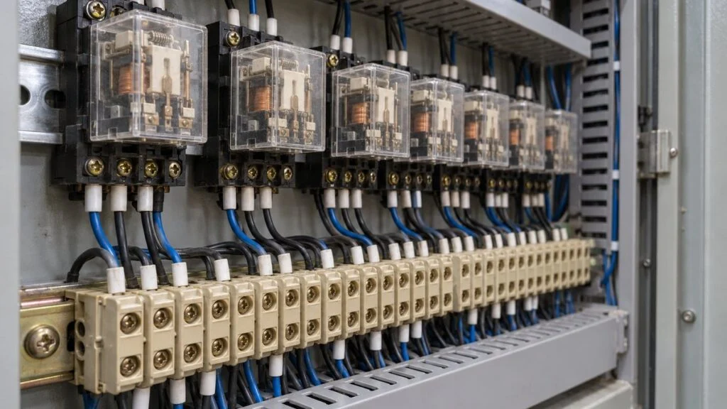
A Japanese supplier sends the I/O list for a pump control panel. The run command row says "パルス 1秒" (pulse, 1 second), the running row says "ステータス" (status), and somewhere else you see "保持" (hoji, maintained). All of these are ON/OFF digital signals, but the receiver treats them very differently. Get one wrong, and the pump may stop one second after it starts, or restart on its own after a stop.
The short answer: a pulse signal turns ON for a fixed, short time, and its meaning is in the moment it switches from OFF to ON. A status signal stays ON for as long as a condition is true, and its meaning is the ON state itself. A status signal is also called a level signal or a maintained signal.
This guide covers how each signal works, why a pulse command needs a self-holding circuit, how pulse counting works for flowmeters and energy meters, and what to agree on with the other side before you connect a DCS to equipment. It ends with the Japanese terms you will see on the list, a checklist, and questions you can send to the supplier.
Starting and stopping a pump remotely. The commands are short pulses; the running signal is a status signal. The ON times are completely different.
The top two rows are pulse signals; the bottom row is a status signal. The 1-second pulse is an example. The actual length is set by the receiving equipment or the DCS.
Contents
- Pulse Signals: Short Commands and Counts
- Status Signals: The Current State, Held ON
- Pulse vs Status Signals: When the Signal Means Something
- Pulse Counting: How Totalizer Pulses Work
- Matching Signal Types Between the DCS and the Equipment
- Japanese Terms You Will See on the I/O List
- Checklist: Pulse and Status Signals on Each Row
- Questions to Send the Japanese Supplier
- Limits of This Guide
- FAQ
- Sources
Pulse Signals: Short Commands and Counts
A pulse signal exists for a set time only. With a "1-second pulse," the voltage turns ON, stays ON for one second, and returns to OFF. Pulse signals have two main uses:
- A trigger that starts an action, such as a run or stop command
- Counting a totalized quantity, such as flow or energy
As a command, the pulse works like a start button that you press and release. Because the pulse disappears almost immediately, a machine that should keep running after the trigger needs a self-holding circuit (自己保持回路, jiko-hoji kairo) in its power circuit, which English sources call a seal-in or latching circuit. Once the relay or magnetic contactor picks up, it feeds its own coil through one of its own a-contacts (normally open contacts), so it stays energized after the command goes away. For how this looks in ladder logic, see How to Read Japanese PLC Programs.
The self-holding circuit in the control panel converts a short command into a "keep running" state.
Example where the stop command is also a pulse. Actual circuits differ from one piece of equipment to the next.
A power failure also drops the seal-in, because the coil loses power. With a pulse-and-self-holding circuit, the machine therefore stays stopped when power returns, until the next run command arrives.
There are exceptions. Some magnetic contactors are designed to stay closed through power loss: the delayed-release type (遅延釈放形) holds through a momentary dip (1–4 seconds on Mitsubishi Electric's models), and the mechanical latch type (機械ラッチ式) stays closed during a power failure. A circuit that receives a maintained run command can also restart when power comes back. Check how each piece of equipment behaves on power return rather than assuming.
Related: Interlock Circuit Diagrams: How to Read Japanese Drawings
The second use is passing a total. Flowmeters and energy meters send one pulse each time a set quantity has passed, and that quantity per pulse is a parameter in the meter. Even though both are "pulses," a command pulse is just one way of driving an ON/OFF signal (DI/DO), while a totalizer pulse is handled as a counted signal (PI/PO). For how these signal types and directions are named on a Japanese list, see DI/DO, AI/AO, PI/PO Meaning: Reading a Japanese I/O List.
Related: 4-20 mA vs 1-5 V: Why Japanese Panels Use 250 Ω Inputs
Status Signals: The Current State, Held ON
A status signal shows the present state of a device. A level switch contact and a "motor running" contact are typical examples. The signal stays ON for as long as the condition is true and returns to OFF when it is not, so the receiving side can follow changes as they happen. That makes status signals the right choice for watching whether equipment is running and whether the process is normal. Common status signals include:
- Running / stopped
- Fault (abnormal)
- Level switch high / low
- Automated valve open / closed (limit switches)
- Local / remote operation selected
For how limit switch contacts report valve open/closed positions, and what to check when that feedback is missing, see our article on valve sticking alarms.
This guide uses "status signal" for any signal whose meaning is the ON or OFF level itself. The same thing is called a level signal, and Japanese plants also say 保持信号 (hoji shingo, maintained signal) or 状態信号 (jotai shingo, state signal). Usage varies by company and industry, so do not judge by the name alone. Confirm what the signal actually does with the other side.
Pulse vs Status Signals: When the Signal Means Something
The whole difference is when the signal carries meaning. A pulse signal means something at the moment it changes from OFF to ON. A status signal means something for the entire time it stays ON.
The split comes down to whether the receiver looks at "the moment it changed" or "the state right now."
Some designs return a fault signal on a b-contact (normally closed) that opens on fault. Agree on which contact type is used and record it on the I/O list. Pulse width is also agreed with the other side on the list.
PLCs make the same distinction internally. Mitsubishi Electric's instruction list separates "ON execution," where an instruction runs every scan while its input is ON, from "rising-edge execution," where it runs only when the input changes from OFF to ON. The PLS instruction creates a pulse on the rising edge that stays ON for one program scan only. The Japanese PLC program guide explains the scan cycle.
As a rule of thumb, use a pulse for an action that should happen once and a status signal to report how things are right now. If you report running status with a pulse, a system that starts monitoring partway through has no way of knowing the current state.
Pulse Counting: How Totalizer Pulses Work
Pulse counting means counting the pulses that arrive and multiplying by the quantity each pulse represents (the pulse weight) to get a total. It is used for totalized flow from flowmeters, totalized energy from energy meters, and gas and water meter reading. For example, a flowmeter set to 1 pulse = 0.1 m³ that sends 1,200 pulses in an hour has passed 120 m³ in that hour. The I/O list guide walks through this example in its PI/PO section.
If the receiving side is set to 1 m³ per pulse instead, the same 1,200 pulses show up as 1,200 m³, ten times too high. A wrong total is hard to spot later, so compare the transmitter's display with the receiving side's value during commissioning.
Pulses also come slow or fast, and the counting device has to match the speed.
Pulse counting ranges from about one pulse per second to hundreds of thousands per second.
Values are examples from manufacturers' product specifications. The pulse rate and width a device can accept depend on the model and its settings.
A pulse shorter than the receiver's read interval can be missed entirely. A PLC reads its inputs once per scan, so a pulse that starts and ends between two reads is never seen. Panasonic's sensor documentation describes adding an off-delay to a short sensor output so that it lasts longer than the PLC scan time. For fast pulses, use a high-speed counter.
Pulses are good at counting how much has flowed but poor at showing the current rate, such as m³/h. A common setup takes the instantaneous value as a 4–20 mA analog signal and the total as pulses.
Related: Retrofit Machine Monitoring on Older Japanese Machines
Matching Signal Types Between the DCS and the Equipment
When a DCS operates equipment remotely, the sending side and the receiving side must use the same signal type. Matching the signal names is not enough. Confirm whether the receiver acts while the signal is ON or on its rising edge.
Put each signal on one row with its direction, type, and receiver behavior, then agree on it with the other side.
Illustrative example. With a maintained run command, ON means run and OFF means stop, and a separate stop command wire may not be used.
When the two sides do not match, the circuit design tells you what to expect:
- Pulse sent to a circuit that expects a maintained signal: the equipment stops when the pulse ends (one second later with a 1-second pulse).
- Maintained signal sent to a self-holding circuit: after a stop pulse ends, the run command that is still ON can start the equipment again.
- Pulse too short: the receiver may not read it, and the command never arrives.
Working through the interface in this order reduces gaps:
- What does the signal carry: a one-time command or a current state?
- Does the receiver act while the signal is ON, or on the rising edge?
- What is the pulse width? For totals, what are the pulse weight and the maximum pulse rate?
- If the wire breaks or communication stops, should the equipment stop or keep running?
Write the result on the I/O list, down to "maintained or pulse" and the pulse width. The sample signal list in the I/O list guide uses the same columns.
Related: How to Read Ladder Diagrams: Mitsubishi and Omron Basics
Related: Japanese Machine Control Panels: UL 508A, NFPA 79, and CE
Japanese Terms You Will See on the I/O List
| Japanese | Romaji: meaning | What to check |
|---|---|---|
| パルス | parusu: pulse (momentary) | Pulse width; whether it is a command or a totalizer pulse |
| パルス幅 | parusu-haba: pulse width | That the receiver can read it (longer than its read interval) |
| 保持 | hoji: maintained | Whether the receiver uses self-holding logic, which could restart the equipment after a stop pulse |
| ステータス/状態信号 | sutetasu / jotai shingo: status / state signal | a-contact or b-contact |
| レベル信号 | reberu shingo: level signal | Same meaning as a status signal |
| 自己保持 | jiko-hoji: self-holding (seal-in) | How the circuit is released (stop command, power loss) |
| 立上がり | tachiagari: rising edge | Whether the receiver acts on the edge or on the ON state |
| 1パルスの重み | ichi-parusu no omomi: pulse weight | Same value on both sides |
| 運転指令/停止指令 | unten shirei / teishi shirei: run command / stop command | Pulse or maintained; stop priority |
| 運転中 | untenchu: running | a-contact or b-contact |
| 故障 | kosho: fault | a-contact or b-contact; reset method |
| 取り合い | toriai: interface (responsibility boundary) | Who decides the signal type on each side |
Checklist: Pulse and Status Signals on Each Row
- Signal purpose: one-time command, current state, or totalized quantity
- Command type: pulse or maintained, written on the list for every command row
- Receiver behavior: acts on the rising edge (self-holding) or only while ON
- Pulse width: long enough for the receiver to read it
- Stop logic: a separate stop command exists when the run command is a pulse; stop priority confirmed
- Status contacts: a-contact or b-contact for running, fault, and other status rows
- Totalizer pulses: pulse weight, pulse width, and maximum rate match on both sides
- Counter type: standard input or high-speed counter, chosen for the pulse rate
- Power return: whether the equipment restarts on its own when power comes back
- Signal loss: what the equipment should do if the wire breaks or communication stops
- Commissioning: totals on the transmitter display and the receiving system compared
Questions to Send the Japanese Supplier
You can paste these into an email and adjust the tag names:
- For the run and stop commands to [equipment tag], does your panel expect a pulse or a maintained signal? If pulse, what pulse width do you need, and is there a minimum?
- Does your panel seal in on the rising edge of the run command, or run only while the command is ON?
- Is the stop command given priority over the run command in your circuit?
- For the running and fault signals, are the contacts a-contacts (NO) or b-contacts (NC)? How is a fault reset?
- After a power failure, does the equipment restart by itself when power returns, or does it wait for a new run command? Do you use delayed-release or mechanical latch contactors?
- For each totalizer pulse output, what are the pulse weight, the pulse width, and the maximum pulse rate?
- If the signal from our DCS is lost, should your equipment stop or keep running?
Limits of This Guide
- Pulse widths, contact types, and stop logic shown here are examples. The actual values come from the equipment specifications and the agreement between both sides.
- Terms such as "status," "level," and "maintained" are used differently by different companies and industries. Confirm the intended meaning and the actual signal behavior with the supplier.
- How equipment should behave on signal loss or power return is decided for each installation. This guide only lists what to ask.
- Counter specifications (pulse rate, minimum width) differ by model and setting. Check the datasheet of the actual device.
FAQ
What Is the Difference Between a Level Signal and a Pulse Signal?
A level signal carries its meaning in its ON or OFF state and is the same as a status signal. A pulse signal is short, and its meaning is in the moment it changes from OFF to ON. Ongoing facts such as "running" go on a level signal; one-time requests such as "start" go on a pulse.
What Is Pulse Counting?
Pulse counting adds up the pulses received and multiplies the count by the quantity per pulse to get a total. It is common for totalized flow and totalized energy. To count correctly, set the same pulse weight and pulse width on both sides and confirm that the receiver can keep up with the pulse rate.
Should a Run Command Be a Pulse or a Maintained Signal?
Both are used, and neither is always right. The difference shows when the command is lost. With a maintained command, the equipment stops when the command drops. With a pulse and a self-holding circuit, the equipment keeps running, so you need a stop command to stop it. Decide by working through the four questions in "Matching Signal Types Between the DCS and the Equipment."
Why Does My PLC Miss Pulses?
A common cause is a pulse that is shorter than the receiver's read interval. A PLC reads inputs once per scan, so it cannot see a pulse that ends between reads. Typical fixes:
- Lengthen the pulse (for example, with a sensor off-delay)
- Use a high-speed counter module
- Increase the pulse weight so fewer pulses are sent
Sources
- ON execution vs. rising-edge execution, and the PLS instruction: Mitsubishi Electric FA e-Learning, "Q Series PLC Instruction List" (Japanese)
- High-speed counter speed (200 kpulse/s, DC input): Mitsubishi Electric, MELSEC iQ-R high-speed counter modules
- Meter pulse input (pulse width, input frequency, pulse rate): Azbil Kimmon, "Pulse Counter KDC-812 Product Specifications" (Japanese)
- Sensor off-delay and PLC scan time: Panasonic sensor glossary, "What Is a Timer Function?" (Japanese)
- Magnetic contactors that stay closed through power loss (mechanical latch, delayed release): Mitsubishi Electric, magnetic contactors product page (Japanese)
Original article in JapaneseThis guide is adapted from a MONOSCOPE article written for readers in Japan: パルス信号とステータス信号の違いとは?レベル信号・パルスカウントも整理
About the editor
 MONOSCOPE EditorFOUNDER & EDITOR
Spent about ten years at a plant equipment maker and a plant engineering company, proposing, designing, and commissioning equipment, then moved into web marketing. Now a web consultant for B2B manufacturers, helping them explain their products and technology. Licensed in Japan as an Energy Manager and a Third-Class Chief Electrical Engineer.
Has run an engineering blog since 2017 (500+ articles) and a Japanese YouTube channel with about 20,000 subscribers. Each English guide is written from the Japanese shop-floor point of view and checked against the cited standards.