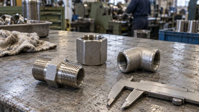
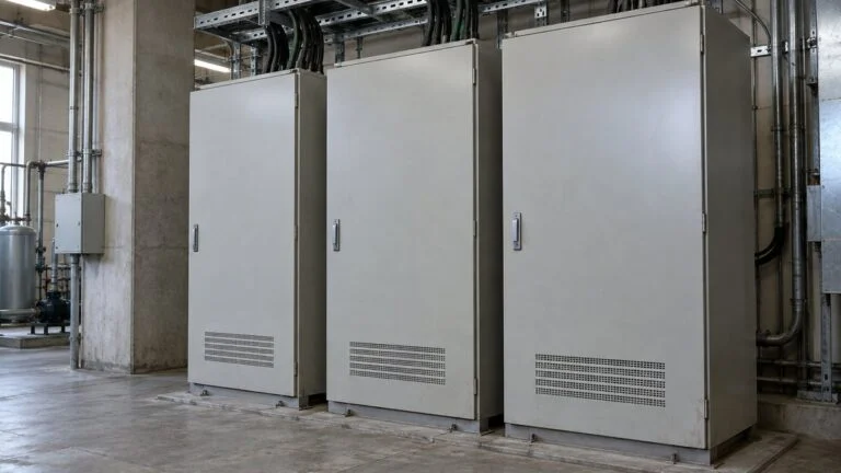
Fabrication Drawings vs Layout and Approval Drawings
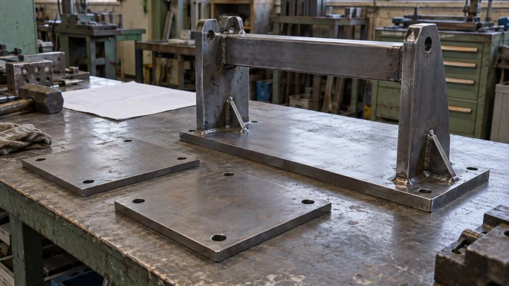
A Japanese engineering, procurement, and construction (EPC) contractor sends your team drawings for a pipe rack support frame and a storage tank. One set is titled 計画図, another is stamped 承認願, and a third is titled 製作図. Before anyone replies, you need to know which set to comment on, which set can go to the shop, and what your return stamp will mean.
These Japanese names map only loosely to English drawing names. Keikaku-zu (計画図) is close to a layout or general arrangement (GA) drawing, seisaku-zu (製作図) is close to a fabrication or shop drawing, and kansei-zu (完成図) is close to an as-built drawing.
Shonin-zu (承認図, approval drawing) is the odd one out, because the name includes a procedure: the buyer checks a submitted drawing and the two sides agree on its content. This guide explains how the terms line up, how drawings move from layout to as-built, and how to review them. It ends with a checklist and an email template you can reuse.
Contents
- Japanese Drawing Names and Their Closest English Terms
- How Drawings Move from Layout to As-Built
- What a Layout Drawing (Keikaku-zu) Must Show
- What a Fabrication Drawing (Seisaku-zu) Must Show
- Review Order: Does It Fit, Can It Be Built, Can It Be Measured?
- Approval Drawings: Return Codes, Issue Status, and Responsibility
- How a Nozzle Orientation Change Ripples Through the Drawings
- As-Built Drawings: What to Check at Handover
- Checklist: Before You Return a Drawing to a Japanese Supplier
- Limits of This Guide
- FAQ
- Sources
Japanese Drawing Names and Their Closest English Terms
Use this table as a starting point rather than a translation key. The last column shows where a one-word translation can mislead you.
| Japanese term | Closest English terms | Main purpose | Where the match breaks |
|---|---|---|---|
| 計画図 keikaku-zu | Layout drawing, general arrangement (GA) drawing | Test whether the arrangement, connections, and access work | May be an early study with unconfirmed values. An equipment GA from a vendor is usually more detailed. |
| 承認図 shonin-zu | Approval drawing, submittal, drawing issued for approval (IFA) | Confirm and agree on what the supplier will build | Describes a procedure and purpose, not a type of content. A GA or a fabrication drawing can be submitted as a shonin-zu. |
| 製作図 seisaku-zu | Fabrication drawing, shop drawing | Tell fabricators what to make and under what conditions | "Shop drawing" can also cover coordination and installation. Being a seisaku-zu does not by itself mean release for fabrication. |
| 完成図 kansei-zu | As-built drawing, record drawing | Record the completed state for the people who run and maintain the equipment | Usually handed over with specifications, test records, and manuals, not as drawings alone. |
Why Shonin-zu Is Not a Drawing Type
Keikaku-zu and seisaku-zu describe what a drawing contains. Shonin-zu describes what is happening to it: a supplier has submitted the drawing so the buyer can check it against the requirements.
A single sheet can therefore be both a fabrication drawing and an approval drawing, since some suppliers draft the fabrication drawing first and then ask for approval on that draft. On every drawing you receive, read two things separately: its purpose and its approval status.
Fabrication Drawing vs. Shop Drawing
English usage is not settled. Some sources treat the two terms as synonyms, while others use "shop drawing" for coordination with the project and "fabrication drawing" for the later, part-level detail such as welds, bolt locations, tolerances, and finishes.
Seisaku-zu generally sits on the fabrication side. Seko-zu (施工図, installation drawing) is the usual name for site installation and fit-up information, though a frame installation drawing can carry both kinds of information. If your contract says "shop drawings," ask the supplier which sheets it will submit under that name.
General Arrangement Drawing vs. Keikaku-zu
"General arrangement" covers two different scales in English. A plant-area GA shows how equipment and structures sit together, while an equipment GA covers one item.
An equipment GA typically lists these items:
- Overall dimensions
- Nozzle schedule, including size, rating, angular position, and elevation
- Support details and the foundation bolt pattern
- Lifting points and weights
- Materials and design conditions
- An orientation reference for nozzle angles
Because of that level of detail, a vendor's equipment GA sent for review may be what your Japanese counterpart calls a shonin-zu, not a keikaku-zu. Ask which name the supplier uses, and match it to the project's drawing list.
How Drawings Move from Layout to As-Built
The basic sequence is simple: planning fixes the layout and requirements, the buyer checks the supplier's drawings, and fabrication and installation lead to the as-built record. Two things advance separately: how detailed a drawing is, and whether it may be used for fabrication.
The table compares the four drawings by purpose and by the question to settle before each one moves on.
| Point of comparison | Keikaku-zu (layout) | Shonin-zu (approval) | Seisaku-zu (fabrication) | Kansei-zu (as-built) |
|---|---|---|---|---|
| Main purpose | Test whether the concept and layout work | Confirm and agree on the submitted content | Convey fabrication and assembly conditions | Record the completed state |
| Usually prepared by | Designer or buyer side | Manufacturer or contractor | Manufacturer or fabricator | Manufacturer or installation contractor |
| What to look at | Main dimensions, space, interfaces | Match with required specifications, dimensions, and materials | Detailed dimensions, parts, joints, inspection | Work actually done, changes, referenced records |
| Question before moving on | Are the conditions in place for detailing? | What are the return conditions and open items? | Are the items and the revision to use clear? | Do the equipment and documents agree? |
Names matter less than three facts: who prepares a document, who checks it under what conditions, and which revision goes to the next step. Agree on those in writing. Submission alone does not advance the work, as Figure 1 shows.
Fabrication start depends on the return conditions and on whether the corrections were made.
General example only. The project's contract and drawing-control rules set the return codes, the need for resubmission, and the conditions for starting fabrication.
What a Layout Drawing (Keikaku-zu) Must Show
A keikaku-zu shows the concept early in design and tests whether the layout and connections work. Its main subject is how the equipment relates to its surroundings and to the space people need for work, not just the shape of the equipment.
Take a tank inside a building. A plan that shows the tank fits on the floor is not enough, because the layout must also show which way the access door opens and which way the internals come out. Only then can you tell whether operation, inspection, and replacement can continue in that position.
Choose the content to suit the equipment and the question being asked. When the task is fixing equipment positions in a plant, this list gives every designer the same conditions:
- Distance from the layout datum to the equipment center, and installation height
- Equipment legs, foundation, and anchor bolt locations
- Maintenance space, such as pull-out space for internals
- Routing of main piping and the interface with connected equipment
- Swing paths of manholes and access doors
- Vehicle routes, turning paths, and personnel routes
- Nozzle service, connection destination, and conditions still under study
This plan view overlays a horizontal tank's access door, the pull-out space for its internals, and the walkway to check for interference.
Schematic for explanation, with dimensions omitted. Actual space comes from the manufacturer's inspection procedure, the removal method, and the site conditions.
Datums, Elevations, and Plant North
Locate equipment from building grid lines or a site datum, not only from the neighboring equipment. With a shared datum, overlaid civil, mechanical, and piping drawings show exactly where positions disagree.
Height needs a shared reference too, so label floor level, foundation top, and equipment centerline separately. If someone confuses the equipment centerline elevation with the elevation where the legs sit, the error appears when the piping connects and can force supports to be remade.
The manufacturer's "front" and the site's north may not match. Plant north is a reference direction set for the site, usually aligned with the plant grid so that drafters avoid working at an awkward angle from true north. Plot plans commonly show both, so align to plant north and mark the equipment's front direction to share nozzle and access door orientations.
The foundation designer needs more than the outline and leg positions: weights and the forces at each support matter as well. Check these against the loading data, because the layout drawing alone cannot set the foundation design conditions.
Operating Position vs. Maintenance Position
Equipment that fits in its normal state can still hit an adjacent pipe when the internals come out. Draw the operating outline in solid lines and overlay the maintenance envelope in dashed lines so that both states can be compared.
Pull-out space depends on more than the length of the part. Include the position of the person holding the tools, the rigging attachment, and a place to set down removed parts to judge whether the work is feasible.
For doors and manholes, draw the path of travel as well as the open position. A door that clears the piping can still block a walkway, so plan the personnel route during the work.
Vehicle checks need the outward swing during a turn as well as the vehicle's width. Connect the route from the unloading point to the installation position, and avoid a layout where a new unit can come in but a replacement cannot go out.
These space checks also affect future shutdown work. Listing inspection items and replacement parts up front produces a layout that follows the maintenance workflow.
Free Format, but Traceable Reasoning
The format of a keikaku-zu follows its purpose, so make clear what each sheet is meant to decide. If the sheet tests a layout, readable walkways, inspection zones, and connection points matter more than every weld dimension.
A free format does not excuse ignoring drafting conventions. Keep scale, units, datums, and legends consistent, and separate approximate values from confirmed ones so that another engineer can follow the assumptions behind the study.
When a placeholder equipment dimension is used, mark that value as not yet confirmed by the manufacturer. Note also how far a later change would reach into foundations and piping, so that the team can decide whether to start that work early.
A piping connection diagram and an equipment placement drawing answer different questions. Confirm the connections on the piping and instrumentation diagram (P&ID), then study the physical route on the layout drawing.
What a Fabrication Drawing (Seisaku-zu) Must Show
A seisaku-zu lets fabricators read the shape and requirements of a part and then make and assemble it. The drawing carries over the positions and main dimensions from the planning stage and turns them into the information needed to cut material, drill holes, and join parts.
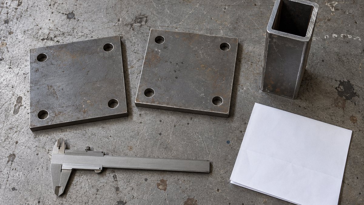
An assembly drawing and a part drawing play different roles, even for the same frame. The assembly shows overall positions and carries part numbers, and those numbers lead to part drawings and a bill of materials (BOM), which together define the finished item.
On plate and structural fabrications (seikan-hin, 製缶品) such as tanks and frames, similar shapes can need different work because of plate thickness or joint type. A picture of the shape is not enough; the conditions set in the specification must reach the drawing.
A fabrication drawing set typically carries the following information:
- Overall assembly arrangement, outline, and mounting positions
- Detailed dimensions, angles, and tolerances needed for fabrication
- Weld locations and methods, marked as shop or field work
- Interface details for connected equipment and piping
- Part details, materials, quantities, and part numbers
- Insulation, painting, and other finish information
- Notes to follow during fabrication, assembly, and inspection
Support spacing and the hole pattern on one plate are separate pieces of information. Part numbers link them so that fabricators do not have to guess.
Schematic of the structure, not a fabrication instruction. Each design specifies its own welding, tolerance, and inspection conditions.
Link Part Numbers to the Bill of Materials
Part numbers connect the shape on the drawing to the material order. If left-hand and right-hand parts share one number, a correct drawing can still produce the wrong set, so give each hand its own number.
The BOM should tie each number to its name, material, main dimensions, quantity, and whether the item is bought or made. When a drawing is revised, update BOM quantities and material ordering conditions along with the shape.
When several units of a part are used, state whether the quantity is per assembly or the total to order. Design and manufacturing often structure the same product differently, a gap usually discussed as engineering BOM vs. manufacturing BOM.
For purchased items, check connection dimensions and mounting direction as well as the model number. A substitute with a similar outline but a different hole spacing or port position can force the surrounding fabricated parts to be remade.
State the Measuring Datum and Tolerance Together
Dimension from a clearly identified face or center. Correct outer dimensions do not convey how a part mates with its neighbor if the mounting hole positions are undefined.
The dimension sets the target, and the tolerance sets the allowed range. Tight tolerances everywhere add machining and inspection work, so separate features that need precision for their function from features where general accuracy is enough.
A length can pass while a tilted face or misplaced hole still fails the function. Use geometric tolerances for requirements that size alone cannot express, and be clear about what they must guarantee.
Also check which tolerancing standard governs the drawing. The usual references are ASME Y14.5-2018 (reaffirmed in 2024) in the US and ISO 1101:2017 internationally. JIS B 0021:1998, the Japanese standard, is based on an earlier ISO 1101 draft (ISO/DIS 1101:1996), so it is comparable to the ISO family but not interchangeable with ASME, and a Japanese drawing may not follow the current ISO edition either.
Tolerance Stack-Up: 100 ± 0.2 Plus 200 ± 0.3
When two parts sit end to end, each tolerance affects the assembled length. Figure 4 calculates the worst case using lengths and tolerances chosen only for illustration.
This is a simple case of parts in series. To set part tolerances, work backward from the allowable assembled length.
Illustrative values, not recommended tolerances for frames or tanks. Welded structures also need separate study of shrinkage, weld orientation, and mounting datums.
Suppose the mating side allows only 300 ± 0.2 mm. These part tolerances then cannot guarantee a fit for every combination, so before release, decide whether to tighten them or change the design to allow adjustment.
Keep the notation straight when you calculate. In this example, ±0.2 mm is the allowance in each direction, so the full band is 0.4 mm. If a tolerance table gives upper and lower limits, convert everything to one form so that you don't confuse the band width with the ± value.
For unequal upper and lower deviations, calculate the assembly's maximum and minimum separately. Reflect in the formula whether each dimension adds or subtracts, because sitting side by side on a drawing does not mean dimensions should simply be summed.
Statistical methods such as root sum square (RSS) give a smaller figure, about ±0.36 mm here, but they rest on assumptions about the part distributions. Worst-case math is the conservative way to check whether every combination fits.
Chaining every dimension lets the same position be calculated in more than one way and invites contradictions. Dimension from the mounting datum, and separate inspection dimensions from reference information.
Never scale a printed drawing with a ruler in place of a stated dimension, since print settings and scaling change lengths on paper. Show the values and units that fabricators should use on the drawing itself.
Welds, Insulation, Paint, and Inspection
A weld callout needs the required joint conditions and a shop or field designation, as well as the location. Separating what the shop completes from what gets joined after delivery aligns the shipping splits with the scope of site work.
Working positions and equipment differ between the shop and the site, so one drawn line does not convey the work conditions. Link the required groove and inspection conditions to the relevant specification, and take the welding process into account.
For insulated equipment, separate the bare dimensions from the outline with insulation. Nozzles and support brackets that do not project far enough interfere with connections and insulation work, so reflect insulation in the interface details and don't leave the issue to a later stage.
Painting and surface treatment callouts should show the area to treat, as well as the color or process name. Where mating faces or threads must stay untreated, say so, and the fabricator won't have to guess.
Sort out inspection conditions early for anything hidden after completion. If a dimension can't be measured after assembly, agree with the fabricator on what to measure at an intermediate stage and which records to keep.
Review Order: Does It Fit, Can It Be Built, Can It Be Measured?
Before hunting for typing errors in dimensions, compare the drawing with what the equipment must do and with the mating side's conditions. An interface mistake means each part can match its drawing while the whole still won't assemble, and that becomes rework on site.
Next, picture the fabrication and assembly sequence: can tools reach, can fasteners be tightened, can parts be inserted? Finally, follow the measuring datums and acceptance criteria, which exposes drawings that can be built but have unclear inspection conditions.
Section views should reveal hidden steps and plate thicknesses and point to the necessary details. Readers new to Japanese drawings can speed up their review by first learning how projections and sections relate.
Fabrication drawings carry a lot of information, so splitting overview and detail sheets usually reads better than cramming everything onto one. With cross-referenced drawing numbers and part numbers, fabricators and installers can each find what they need.
Write Comments That Can Be Verified
Avoid vague comments such as "recheck dimensions." Cite the mating drawing number and the problem, so that the person making the correction understands the intent and the next submission can be checked against it.
Instead of "hole position is wrong," for example, give the frame drawing number and the equipment drawing number, and record the difference in distance from the datum face. Fabricators should not match one side on their own; the design side settles the interface first.
Split the Review Without Leaving Gaps
When several people review a drawing, assign roles: mechanical checks the outline, piping checks connections, and maintenance checks inspection space. Review boundary areas jointly so that nothing falls out because each side assumed the other had it.
One common arrangement has the manufacturer's or fabricator's designer prepare the drawing, while an internal checker and the buyer each check their own scope. Separate the roles of preparer, checker, and approver, and decide early who judges function and interfaces.
Approval Drawings: Return Codes, Issue Status, and Responsibility
The approval step compares what you ordered with what the manufacturer will build. Follow performance and materials from the purchase specification, along with the dimensions and interfaces that affect layout, one item at a time.
Tracing from each specification requirement to the drawing finds gaps better than starting at the upper left corner of the sheet. A missing material callout or a missing nozzle is easy to overlook if you read only what is drawn.
Typical check points differ by item:
- Tanks: nozzle service and orientation, flange conditions, and mounting positions of level gauges and similar instruments
- Frames: support positions and load conditions, splits for shipping, and the mounting face on the equipment side
Where the two sides have agreed to a specification change, tie it to the deviation list. A drawing that differs from the original specification may not need to go back, so separate agreed changes from unresolved differences.
Also confirm that the manufacturer's delivery specification carries the same changes. If the drawing is new but the inspection procedure or material conditions are old, people will disagree after fabrication about which one applies.
Return Codes Differ by Company
Review results generally fall into three groups: no problem, correct and resubmit, and proceed once conditions are met. Names and meanings vary between companies, so agree on each code and its effect on fabrication at project start.
This table shows wording you may see and a question to ask for each. It is not a standard, and any number your project attaches to a code comes from that project's procedure, not from a common scheme.
| Japanese wording | Common English wording | Question to confirm |
|---|---|---|
| 承認 shonin | Approved | Does this code release fabrication, or is a separate release needed? |
| 条件付き承認 joken-tsuki shonin; コメント付き承認 komento-tsuki shonin | Approved as noted, approved with comments | May work proceed with the comments included? Is a corrected drawing required, and by when? |
| 再提出 sai-teishutsu; 不承認 fu-shonin | Revise and resubmit, rejected | What must change, and has work on these items stopped? |
| 参考図 sanko-zu (a drawing label, not a return code) | For information, for reference only | Does the sheet need a response, and does the contract treat its content as binding? |
Where IFA, IFC, and AFC Fit
English-language projects usually add an issue status to each revision, and this is a different label from a return code. Return codes say how the reviewer responded, while issue status says what the revision may be used for. Japanese drawings have no single fixed counterpart for these labels, so map them explicitly.
| English status | Usual meaning | What to confirm with the Japanese side |
|---|---|---|
| IFA (issued for approval) | Sent to the client for review and approval | Is a drawing stamped 承認願 (shonin-negai, "request for approval") the same as IFA on this project? |
| IFC (issued for construction) | The revision authorized as the basis for building | Which label on the supplier's drawing means use for fabrication, for example 製作用 (seisaku-yo)? |
| AFC (approved for construction) | Often used like IFC, usually implying that the client has approved | Is AFC the same as IFC here, or a separate step? Who gives the approval? |
When a release is revised, the new revision supersedes the old one. Confirm status in writing before work begins, and record which revision was current at the time.
Approval Does Not Automatically Move Design Responsibility to the Buyer
The word "approval" does not mean the buyer has taken on all of the manufacturer's design responsibility. The contract sets the responsibility split and the conditions for starting fabrication, so don't rely on a return stamp alone to interpret them.
Readers from US building projects will recognize a similar idea. Under the AIA A201 general conditions, approval of a submittal generally does not relieve the contractor of responsibility for deviations unless the contractor flagged them in writing at submission and the architect approved them. Contract clauses are often edited, however, so read your own.
Japanese public works can use different terms. On machinery works for Japan's infrastructure ministry (MLIT), the contractor must get shodaku tosho (承諾図書, documents for acceptance) accepted, including specifications, calculations, and detail drawings, and must consult the owner before changing them, except for minor items. Private plants may not use the same names, so both sides should align on the procedure adopted for the project.
Close Comments Before Releasing for Fabrication
Returning a comment does not prove that the correction was made as intended. Log an answer and the corrected drawing number for each comment number, and mark each as corrected, awaiting answer, or to be reflected next time so that open items stay visible.
When fabrication starts, hand over the drawing number, revision number, issue date, and purpose together. Don't mix study copies and fabrication copies under the same drawing number, and make clear which data fabricators should treat as correct.
Sometimes one activity goes first, such as ordering material. Limit the approved scope in writing so that nobody reads the instruction as permission to drill unconfirmed holes or start welding.
Name the target part numbers as well as the activity. Separate material that stays usable after a change from material that would become scrap, and weigh the benefit of an early start against the cost of rework.
How a Nozzle Orientation Change Ripples Through the Drawings
Changing a nozzle's orientation does not end with a corrected tank fabrication drawing. The change reaches the connected piping, the pipe supports, and nearby walkways in turn, so follow the related drawing numbers outward from where the change began.
If the equipment side and piping side view the tank from different directions, a clockwise instruction can be read as counterclockwise. Align the reference direction and viewing direction on the plan view, and show the shape after the change along with the angle.
In this example, a nozzle moves from the top of the plan view to the right side. The list of affected items includes the pipe route and support positions.
Not an actual nozzle design. Sort out the impact on drawing numbers, specifications, ordered items, and finished parts case by case.
Record what changed, why it changed, and who agreed to it. A revision cloud or symbol alone doesn't let another engineer reconstruct the original requirement and the reason for the change.
After issuing a revision, notify the fabricators and contractors who received the earlier version. Replacing a file in a shared folder doesn't tell you whether printed copies on site or data loaded into machines were updated too.
For parts already made, decide part by part whether to use them, rework them, or remake them. Define the allowed scope of work during the wait, so that the next step doesn't go on to assembly without knowing about the change.
On projects with many drawings, revision control and distribution history work better as a system. Whether or not you use product data management (PDM) or product lifecycle management (PLM), the foundation is the link between drawings, parts, and change records.
As-Built Drawings: What to Check at Handover
A kansei-zu records the final configuration reached through fabrication and installation, and it goes to the people who use the equipment after handover. Changing the title of an approval drawing does not make an as-built drawing; check that changes made during the work reached the final state.
If a pipe moved on site, follow that change into the system and support drawings as well. Collecting the red markups and comparing them with the formal as-built reduces missed changes.
The purpose of an as-built is to identify the actual equipment at the next inspection or replacement. Tie together equipment numbers, part numbers, instruction manuals, and test records so that a reader can get from the drawing to the information needed.
Figure 6 is a sample handover check. Decide up front what proves a match, then look for what has not been reflected.
Matching drawing numbers alone is not enough. Each pair below has its own check.
| Pair to compare | Where to look | What to keep on record |
|---|---|---|
| As-built vs. actual equipment | Equipment number, interfaces, changed positions | How site changes were reflected |
| Assembly drawing vs. BOM | Part numbers, materials, quantities | Links that identify replacement parts |
| Drawings vs. test records | Target equipment, test scope, revision referenced | Connection to the specification tested |
| Document list vs. delivered data | Drawing numbers, revisions, files, references | Missing drawings and open items |
A sample to adapt to the project's required submissions. The contract and any specified guidelines set the scope and format of the completion documents.
An as-built drawing rarely stands alone. As one public-sector example, an MLIT guideline for machinery works lists detail drawings alongside specifications, calculations, construction control records, purchased-equipment lists, and instruction manuals in the kansei tosho (完成図書, completion documents).
For electronic handover, specify editable and viewing formats separately. Drawings that reference external files can display differently if a reference is missing, so confirm that the receiving side can open them properly.
If the documents leave items open, list them with the drawing number, planned action, and owner. A shared list keeps maintenance staff from assuming the set is complete and ordering the wrong replacement part.
Checklist: Before You Return a Drawing to a Japanese Supplier
Run through this list before stamping or signing. It follows the review order above and also covers the items that most often need written confirmation.
- Identity: drawing number, revision, issue date, and stated purpose (study, approval, or fabrication)
- Requirements: each purchase specification item traced to the drawing; agreed deviations separated from unresolved differences
- Fit: interfaces checked against mating drawings; datums, elevations, and plant north aligned
- Nozzles: service, size, flange standard and rating, and orientation angle, with the reference and viewing direction stated
- Buildability: tool access, assembly order, shipping splits, and shop vs. field welds
- Measurement: measuring datums, acceptance criteria, tolerancing standard, and intermediate checks for hidden features
- Tolerances: stack-ups checked against what the mating side allows
- Finish: insulated outline, paint and surface treatment scope, and faces to leave untreated
- Your response: return code stated, each comment numbered with a mating drawing number, and any partial release limited by part number
- Responsibility: contract clause or procedure that defines what the return means
Questions to Ask the Japanese Side
Send these early, ideally at kickoff, when no fabrication depends on the answers yet.
- What does each return code mean, and which ones allow fabrication to start?
- How do your drawing labels map to our IFA, IFC, and AFC status?
- Which drawings on the list do you plan to submit for approval, and which for reference only?
- Do you use plant north on nozzle orientation drawings? What is the viewing direction for your angles?
- Which tolerancing standard and edition apply to these drawings?
- What will the as-built package contain, and in which file formats?
Email Template for Returning a Drawing
Adapt this template to your project. Replace the bracketed items, and use the code names from your own procedure.
Subject: Drawing [No.] Rev. [X]: Review Result and Questions
Dear [Name],
We have reviewed Drawing [No.] Rev. [X], [title]. Our return code is [code] under [procedure no.].
Comments:
1. Nozzle [N3]: your drawing shows [angle] degrees from plant north, viewed from above. Our piping drawing [No.] shows [angle] degrees. Please confirm which is correct.
2. Base plate, part [No.]: the hole pitch differs from equipment drawing [No.] by [value] mm measured from [datum]. Please do not change either side until we agree on the interface.Please confirm:
1. Does this code allow fabrication to start, or do you need to resubmit first?
2. If you need to order material early, which part numbers does this cover?
3. When can you send Rev. [Y] with these comments reflected?Our understanding is that this review does not by itself change the allocation of design responsibility under the contract. Please tell us if the contract or your procedure says otherwise.
Best regards,
[Name]
Limits of This Guide
- The term mapping is a general guide. Companies, industries, and contract types use these names differently, and the project's documents control.
- The schematic figures and example tolerance values are illustrations only. They are not fabrication instructions or recommended tolerances.
- Return codes and issue statuses have no universal standard. Sources disagree on some labels, especially AFC vs. IFC.
- This guide is not legal advice. Who holds design responsibility depends on the contract and the applicable law.
- Confirm the current editions of JIS, ISO, and ASME standards before citing them in a specification.
FAQ
What Is the Difference Between a Fabrication Drawing and a Shop Drawing?
Many people use the terms interchangeably. Where they differ, shop drawings coordinate how items fit and install, while fabrication drawings give part-level detail such as welds, tolerances, and finishes. In Japanese usage, seko-zu covers site installation and fit-up, and some drawings carry both, so agree on the required content for each sheet.
Can Fabrication Start Once an Approval Drawing Has a Stamp?
Not automatically. The return code, attached conditions, and open comments decide that, and a conditional return or partial release may apply. Tell the fabricator exactly which drawing numbers, revisions, and scope of work can be used.
Can You Fabricate from Layout Drawing Dimensions?
No, not if the drawing contains approximate or unconfirmed values. Carry over the interfaces agreed with the mating side, define fabrication datums, tolerances, materials, and joining conditions, and then issue a drawing for fabrication.
Does a 3D Model Replace Fabrication Drawings?
That depends on what the model contains and what the fabricator can receive. Shape alone may not convey tolerances or hole conditions, so use drawings or notes as needed to make the applicable conditions clear.
What If As-Built and Fabrication Dimensions Differ?
Compare the change approval records with the actual equipment to find out whether the difference is an intended change or a missed update. A difference in the field does not make a change valid by itself, so trace the agreement and inspection records before updating the as-built.
Sources
- Shop vs. fabrication drawings: Strand, "Shop Drawings vs. Fabrication Drawings"
- GA drawing contents: Project Materials, "What Is a General Arrangement Drawing"
- IFC and AFC use, superseded revisions, written status check: Procore, "IFC Drawings"
- AFC as a separately approved set: Bluent, engineering blog on IFC and AFC drawings
- Review dispositions and inconsistent codes: Kissflow, "Vendor Drawing Approval"
- AIA A201 and submittal approval: Lorman, "AIA 201 Document: Submission of Shop Drawings"; LBCC Law, "Submittal Review"
- Plant north: Wermac, piping coordination; CR4 forum, "Plant North vs True North"
- Worst-case and RSS stack-up: Wevolver, "Tolerance Stack-up Analysis"
- ASME Y14.5-2018: ASME, Y14.5 Dimensioning and Tolerancing
- ISO 1101:2017: ISO, ISO 1101:2017
- JIS B 0021:1998: SAI Global, JIS B 0021:1998 listing
- Documents for acceptance on Japanese public machinery works: MLIT, Common Specifications for Machinery Work, draft (Japanese)
- Completion documents on Japanese public machinery works: MLIT, guideline for machinery work completion documents, draft (Japanese)
Original article in JapaneseThis guide is adapted from a MONOSCOPE article written for readers in Japan: 製作図とは?計画図・承認図との違いと図面の流れ・検図の実例
About the editor
 MONOSCOPE EditorFOUNDER & EDITOR
Spent about ten years at a plant equipment maker and a plant engineering company, proposing, designing, and commissioning equipment, then moved into web marketing. Now a web consultant for B2B manufacturers, helping them explain their products and technology. Licensed in Japan as an Energy Manager and a Third-Class Chief Electrical Engineer.
Has run an engineering blog since 2017 (500+ articles) and a Japanese YouTube channel with about 20,000 subscribers. Each English guide is written from the Japanese shop-floor point of view and checked against the cited standards.